Week5
Electronic production
PCB production
Assignment:
Characterize PCB production process
You can see the complete documentation of group assignments on the opendot website at this LINK.
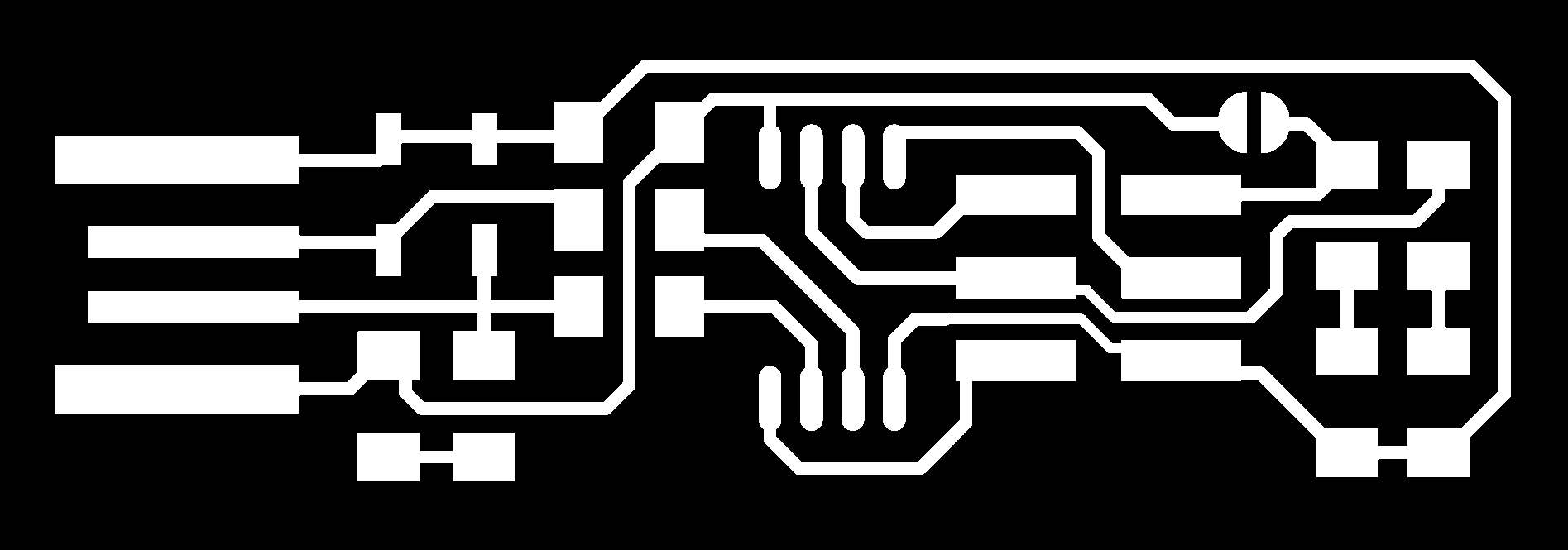
For the characterization of PCB production we uploaded this file (traces) and this (cut) on
fabmodules (check the DPI of the images (1000) and
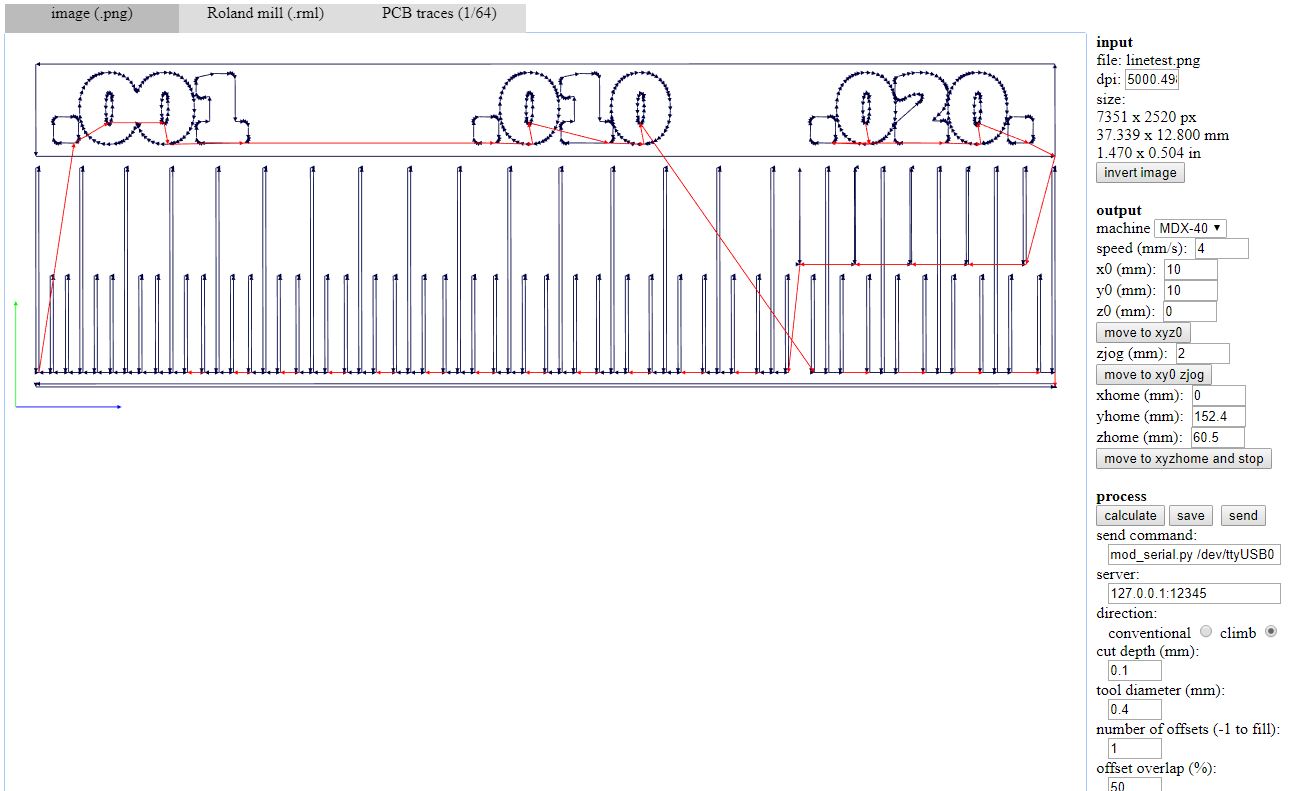
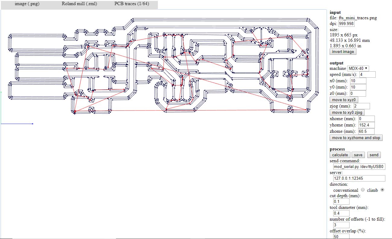
verify that the images have the same size). We started with the traces. We select "Roland Mill" as output format, and "PBC traces 1/64" as process.
After we select MDX-40 Machine. We left the positions of the axis unchanged because I preferred to manage them directly in the cutter software.
We select 4m/s as speed and 0,1 as cut depth, for the traces the diameter of the tool is 0,4 mm.
WARNING: this end mill is very expensive and should be handled with care!
 After, we clicked on "Calculate the path" and save to outcome (an .rml file) on the USB key and started to work on the second file for outline cutting.
We use this settings:
After, we clicked on "Calculate the path" and save to outcome (an .rml file) on the USB key and started to work on the second file for outline cutting.
We use this settings:
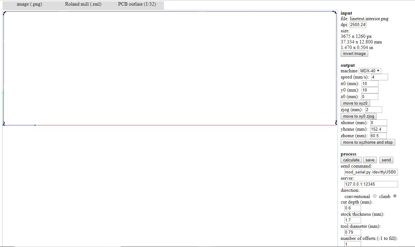 In this case the diameter of the tool is 2 mm, cut depth 0,6 and I set 1 offset.
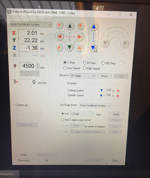
When the file is ok, we can switch to the machine: turn on the computer and the machine itself. On the computer we open the vPanel software to set the XYZ origins as follows. When the machine is inizializated you can open it and you can start to fix the piece to be milled, we used a double-sided adhesive tape to make it adhere to the sacrificial plane. The surface must be very clean.
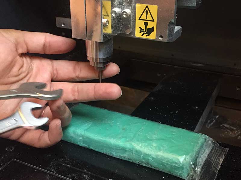
 Then we mount the 0,4 mm end mill: we put piece of clay under the spindle for
to prevent it from falling on the plane with the tip and breaks. Then, from vPanel we start to move Z axis, very very slowly (on the panel you can check how many step do you move it- each step corresponds to 0,01 mm).
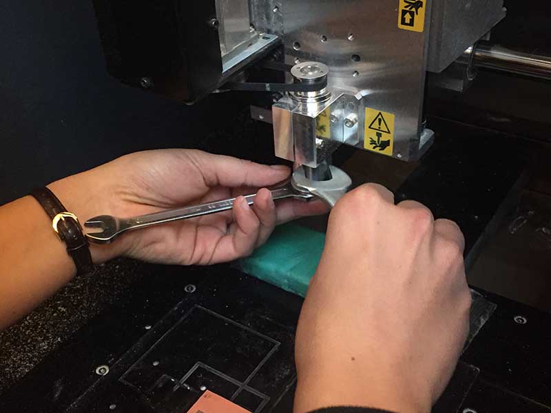
But for the last steps we use a special tool:
Then we mount the 0,4 mm end mill: we put piece of clay under the spindle for
to prevent it from falling on the plane with the tip and breaks. Then, from vPanel we start to move Z axis, very very slowly (on the panel you can check how many step do you move it- each step corresponds to 0,01 mm).
But for the last steps we use a special tool:
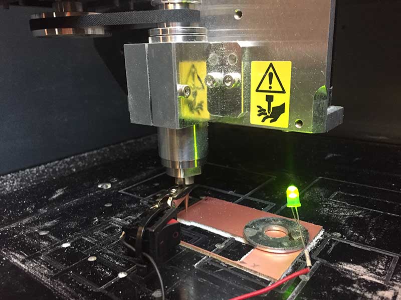 A cleaver trick, available at Opendot: you positioning the magnet of this tool on the end mill: when the tool touches the copper, the circuit closes and the LED lights on!
Now we set the Z origin. Then we move up the Z axis to not scratch the board, and move the heading to the XY origin and set these coordinates as the new XY zero.
At this point we load the rml file from desktop, set the spindle speed to 15000 rpm and launch the cut. (If you want you can use a bit of oil on the board before start).
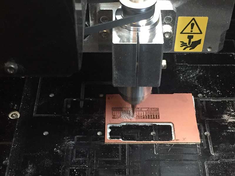
When the machine finish the work we open it and change the end milling in the same way.
 Then you must ret the new Z ero but in this case we used a piece of paper between the tip and the board to figure out how to lower the zeta.
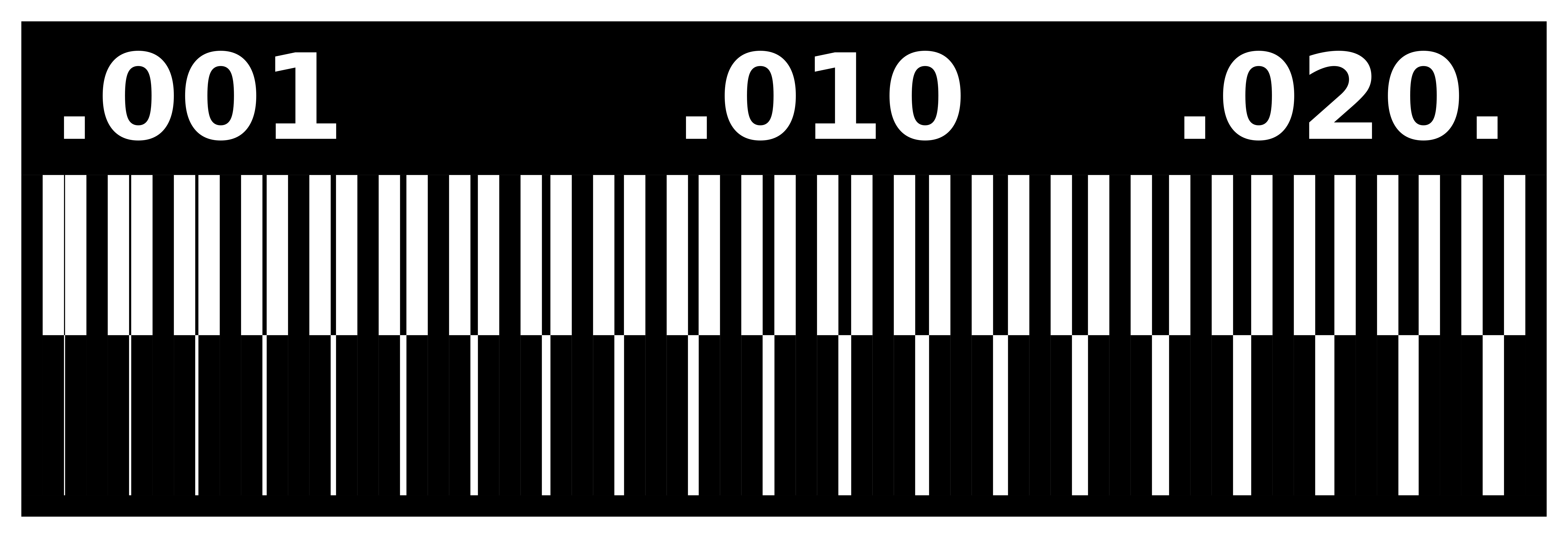
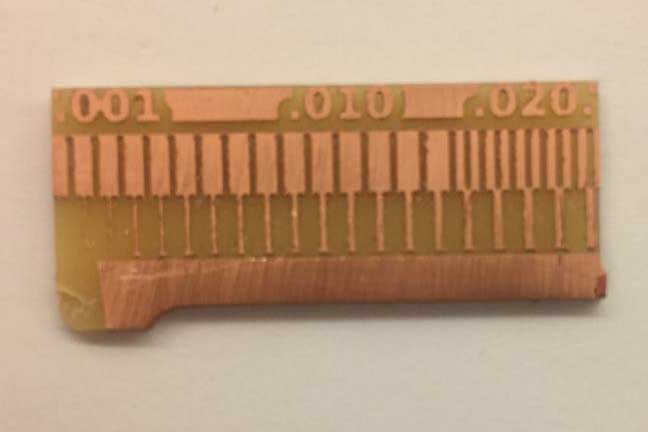
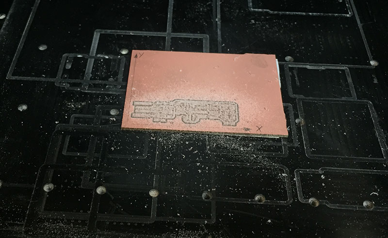
 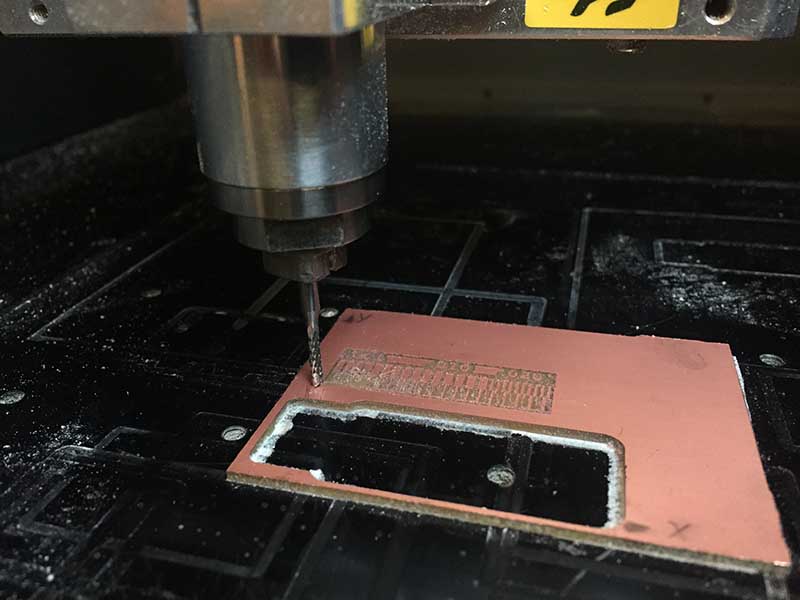 And here is the result of our test:
Building the FabTinyISP
STEP1: Fabrication
For this exercise I choose ATtiny45 of BRIAN. I download the correct resolution images of traces and cut and start to work in the same way of the precedent exercises.
I upload the firt file on
fabmodules (check the DPI of the images (1000) and verify that the images have the same size).And start to create the traces file. I select "Roland Mill" as output format, and "PBC traces 1/64" as process.
I select MDX-40 machine, 4m/s as speed and 0,1 as cut depth, diameter of the tool: 0,4 mm and at the end dedice to use 3 offsets. Then calculate, verirfy that it is correct and save on UBS pen.
 For the CUT FILE I select "Roland Mill" as output format, and "PBC outline 1/32" as process.
Select MDX-40 machine, 4m/s as speed and 0.6 as cut depth, diameter of the tool: 0.69 mm and 1 offset. Then calculate, verirfy that it is correct and save on UBS pen.
For the CUT FILE I select "Roland Mill" as output format, and "PBC outline 1/32" as process.
Select MDX-40 machine, 4m/s as speed and 0.6 as cut depth, diameter of the tool: 0.69 mm and 1 offset. Then calculate, verirfy that it is correct and save on UBS pen.
With the file, I start to set the milling machine. I repeat ALL the step of the characterization of PCB production. I change the end milling with help of clay, I mounted the small tip and I set the Z with the wonderful opendot tool, set all the origin and upload the file of the traces.
 (I did not put a new PCB BOARD because there was still space on the one already mounted in the machine)
 Then I change the milling end and start to set the machine for che cutting file. After this I followed step by step this tutorial for assembling the PCB.
STEP2: Assembling
Bill of Materials (BOM)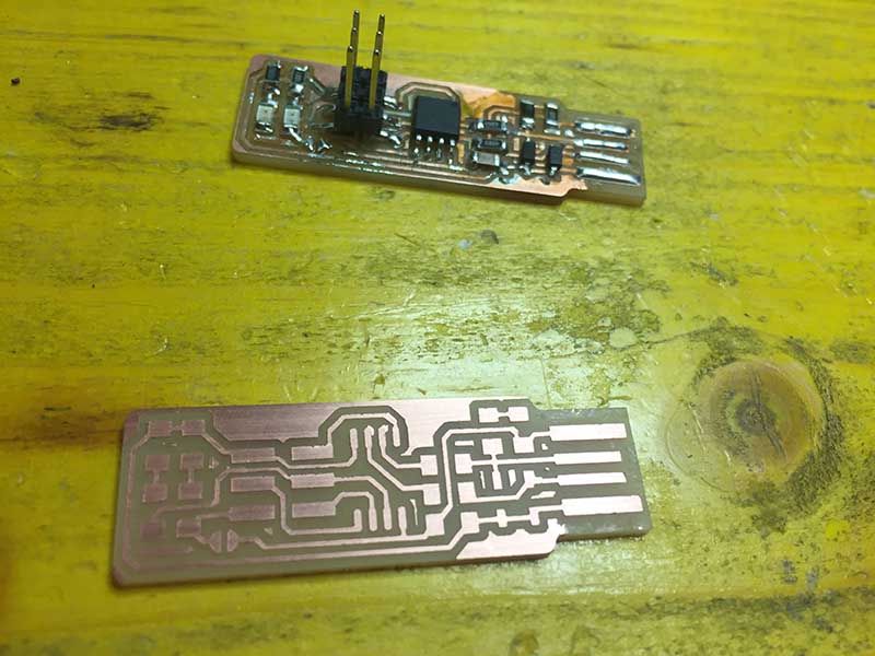
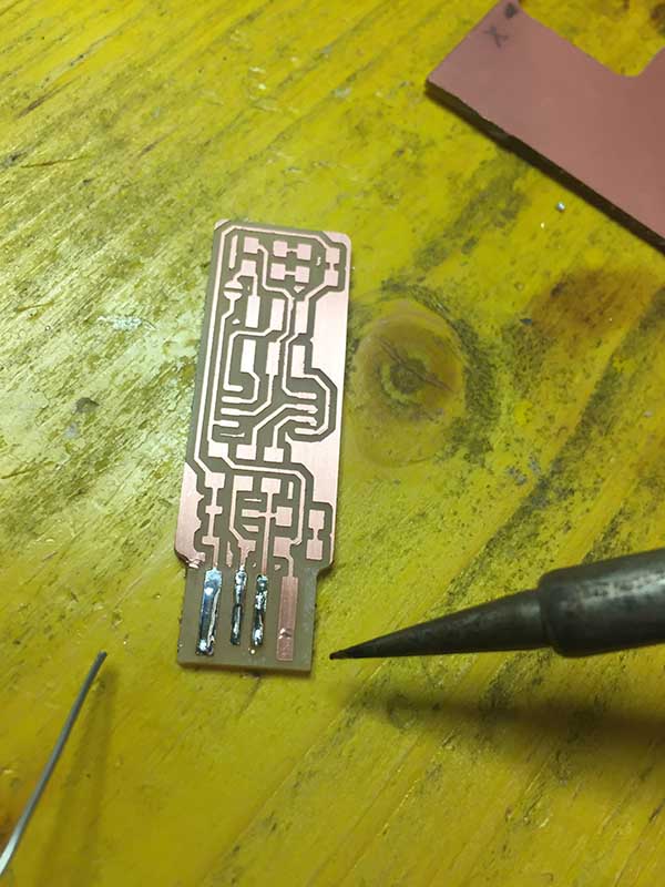
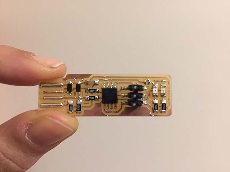
I start with removed the copper in front of the padsand, then I soldered the parts to the PCB, using Enrico PBC as a reference for component values and placement.
My first solder did not come very well. During programming I resumed the board and reviewed all the solder joints made previously.
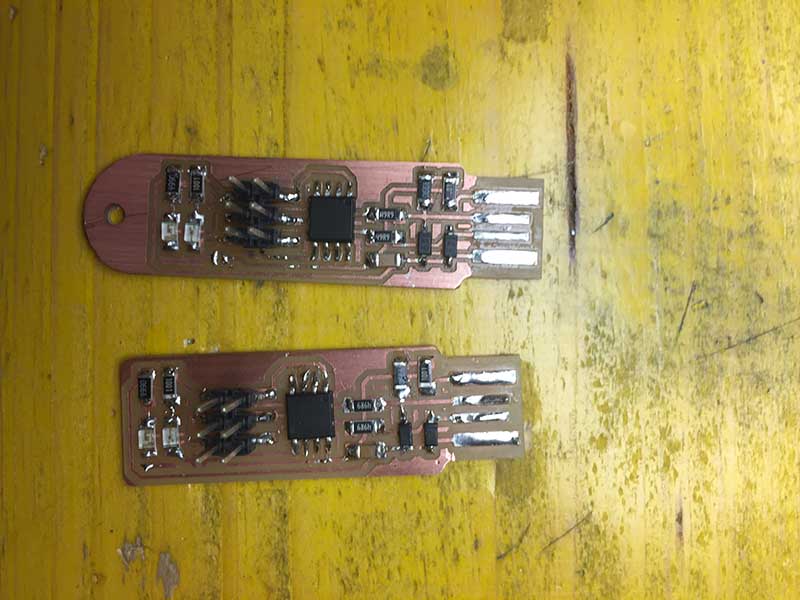
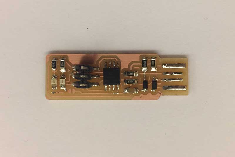
At the time of rechecking the entire board I realized that I had forgotten the bridge and that the red LED had been mounted upside down, so I reviewed everything.
STEP3: programming (part1)
Software InstallationThe longest part of the programming is the step of installing the programs on the Windows operating system. To do this I followed step by step this tutorial.
Programs to be installed and checks to be done:
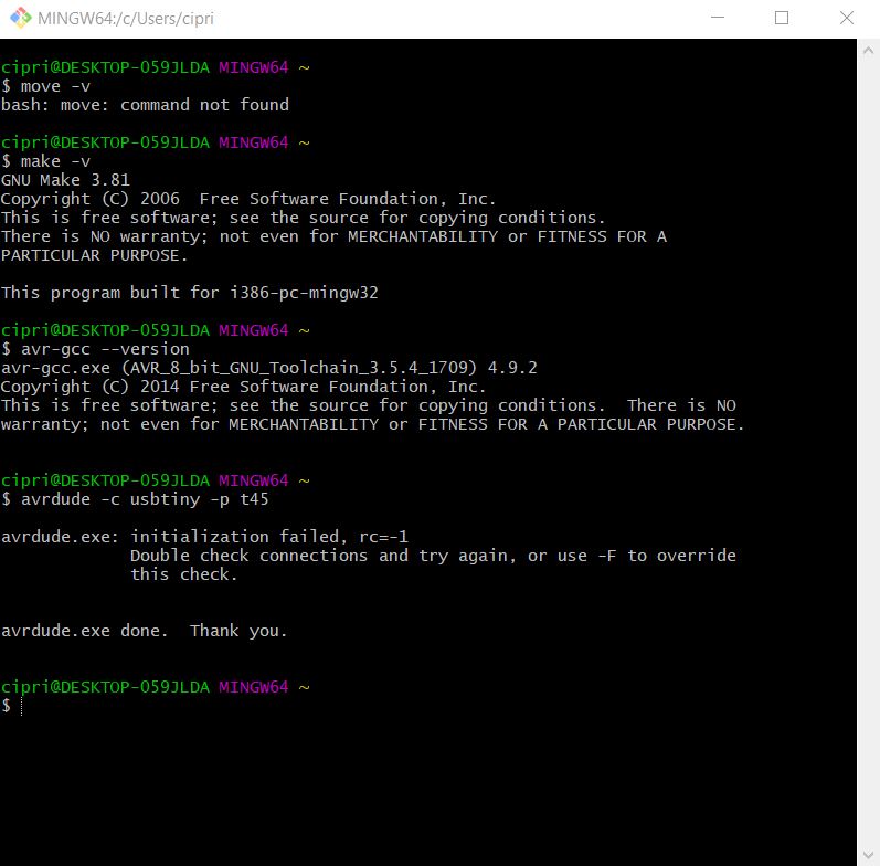
Th last step befor programming is to Build the Firmware, generate the firmware.hex file. It is very simple because you downloaded from tutorial the zip folder, estract all the file and open in git (right click: git bash here on the unzip folder) and then run the command "make". This will build the hex file that will get programmed onto the ATtiny45. When the command completes, you should now have a file called fts_firmware.hex.
STEP3.1: programming(part2)
At this point it should be very simple to program the card because they are only three commands but for me it was not. I started trying using the example card of Henry but the command "make flash" still did not work.
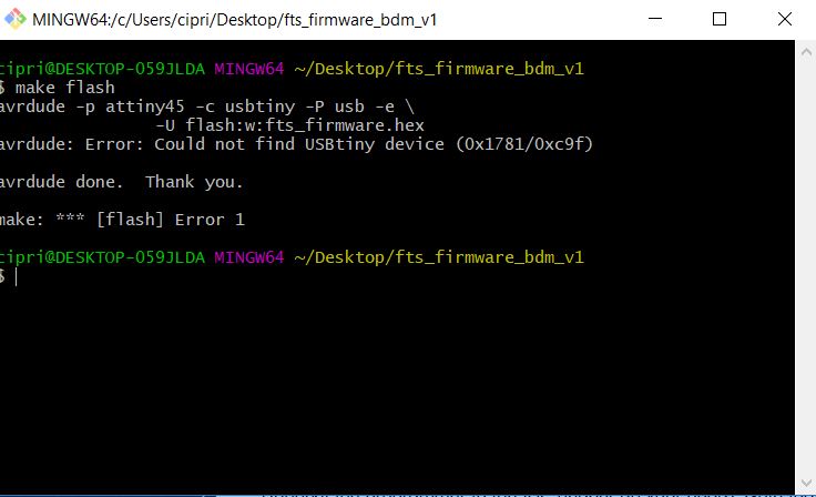 I tried all the possible combinations for more than two hours, reviewed the welds and made the various tests. Only later did I realize that I was mistaken for a number of things:
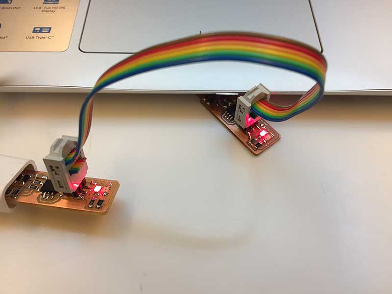
After all these operations I tried again to connect the programmed card and mine to the computer. I ran the "make flash" command back to the firmware folder on git and it worked!
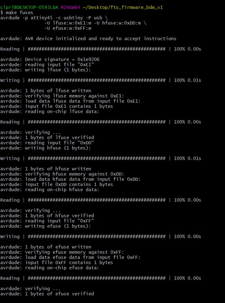
At this point I executed the "make fuses" command and this also worked!
Then I disconnected the programmer and the card just programmed, I hung up this to test it and the computer detected it! then I attached the programmer and the card again and executed the last command:"make rstdisbl".
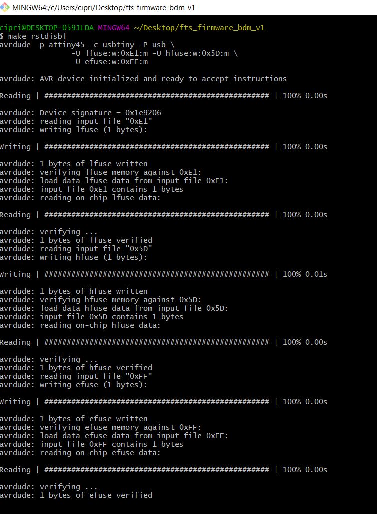
With great satisfaction I removed the bridge on the solder jumper and here we are: my card is programmed and can not be reprogrammed! I can not wait to try it!
 PS: when retouching the welds the red LED is burned, I must remember to change it!