Week8
Computer-Controlled Machining
CNC machine
Assignment:
Test runout, alignment, speeds, feeds, and toolpaths for your machine
You can see the complete documentation of group assignments on the opendot website at this LINK.
For the group assignement of this week we download a joint from Jochen Gros Library. We choose this for try the tolerances, interferences, speeds, tools etc.
 For this test we used used a piece of OSB wood 17mm thick,
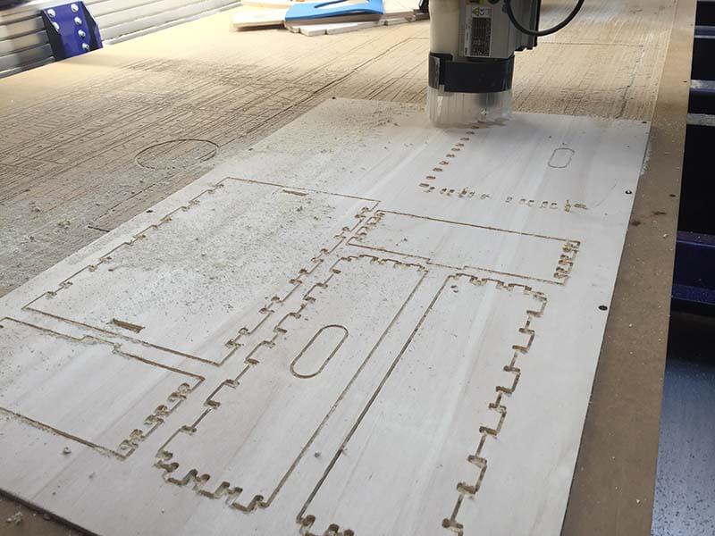
we cut the piece with Shopbot of Opendot.
For this test we used used a piece of OSB wood 17mm thick,
we cut the piece with Shopbot of Opendot.
Part features:
-2D and 2.5D milling fabrication,
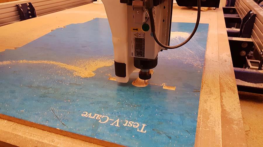
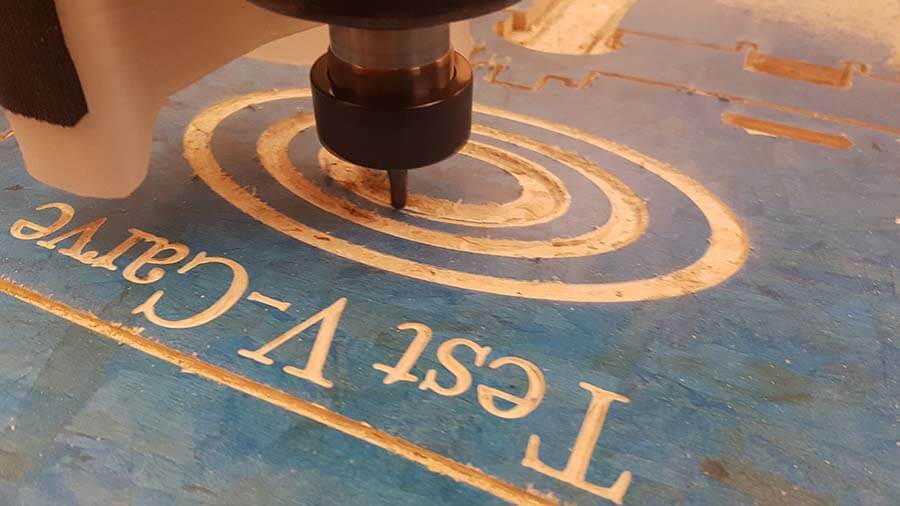
-V-Carve
-3D milling fabrication.
 Layer:
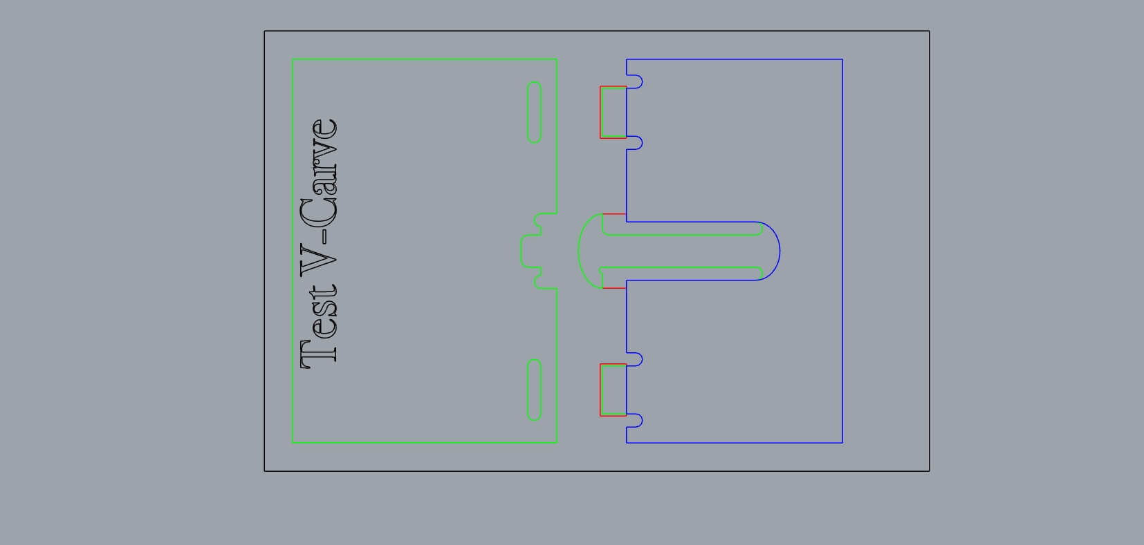
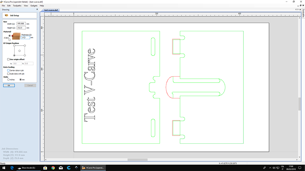
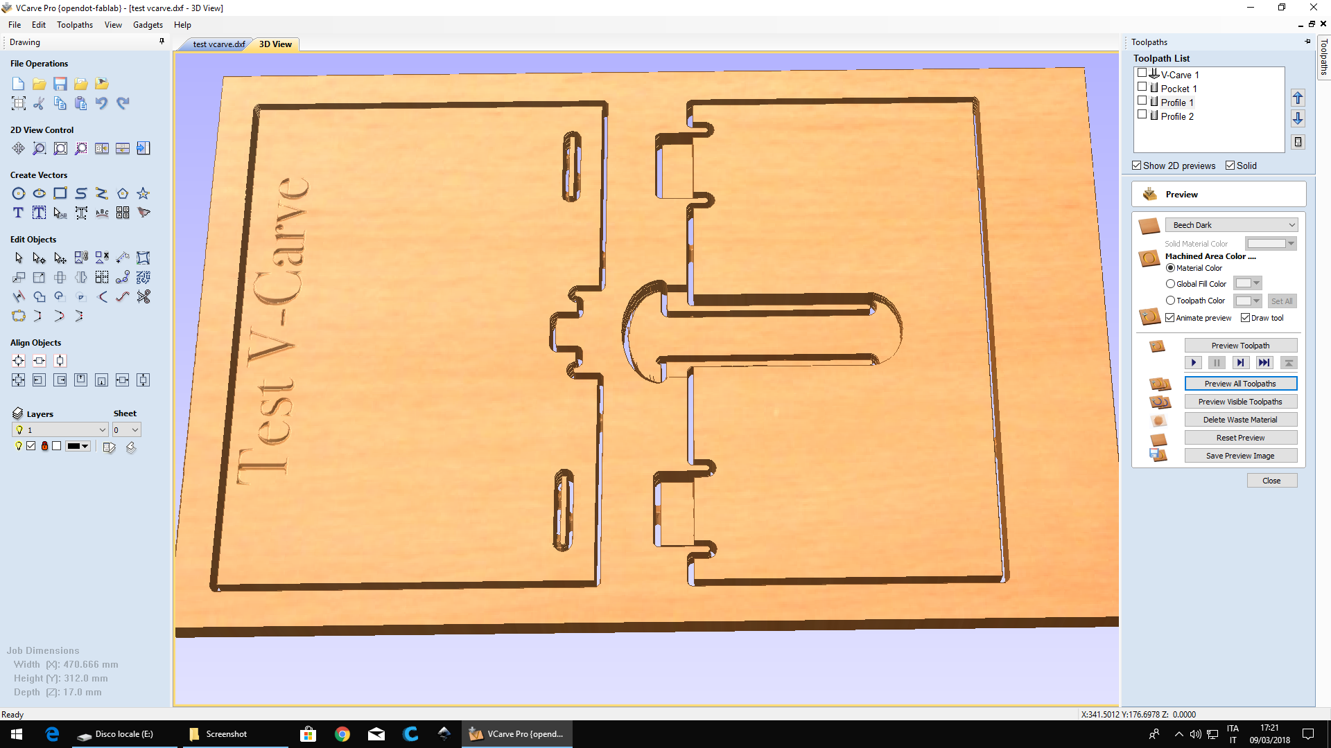
-black: was for V-Carve test. The word "Test V-Carve" are inside this layer, that will be milled with a V-Carve tool.
-red: was for milling in "Pocket settings". We wanted a 7,5 mm cut depth for the areas within red curves. The pieces milled in this layer will be 9,5 thick (17 mm - 7,5 mm = 9,5 mm).
-green: will be the path for cut.
We saved the the drawings in dxf files for edit it in V-Carve, to obtained the ShopBot toolPath (.SBP files).
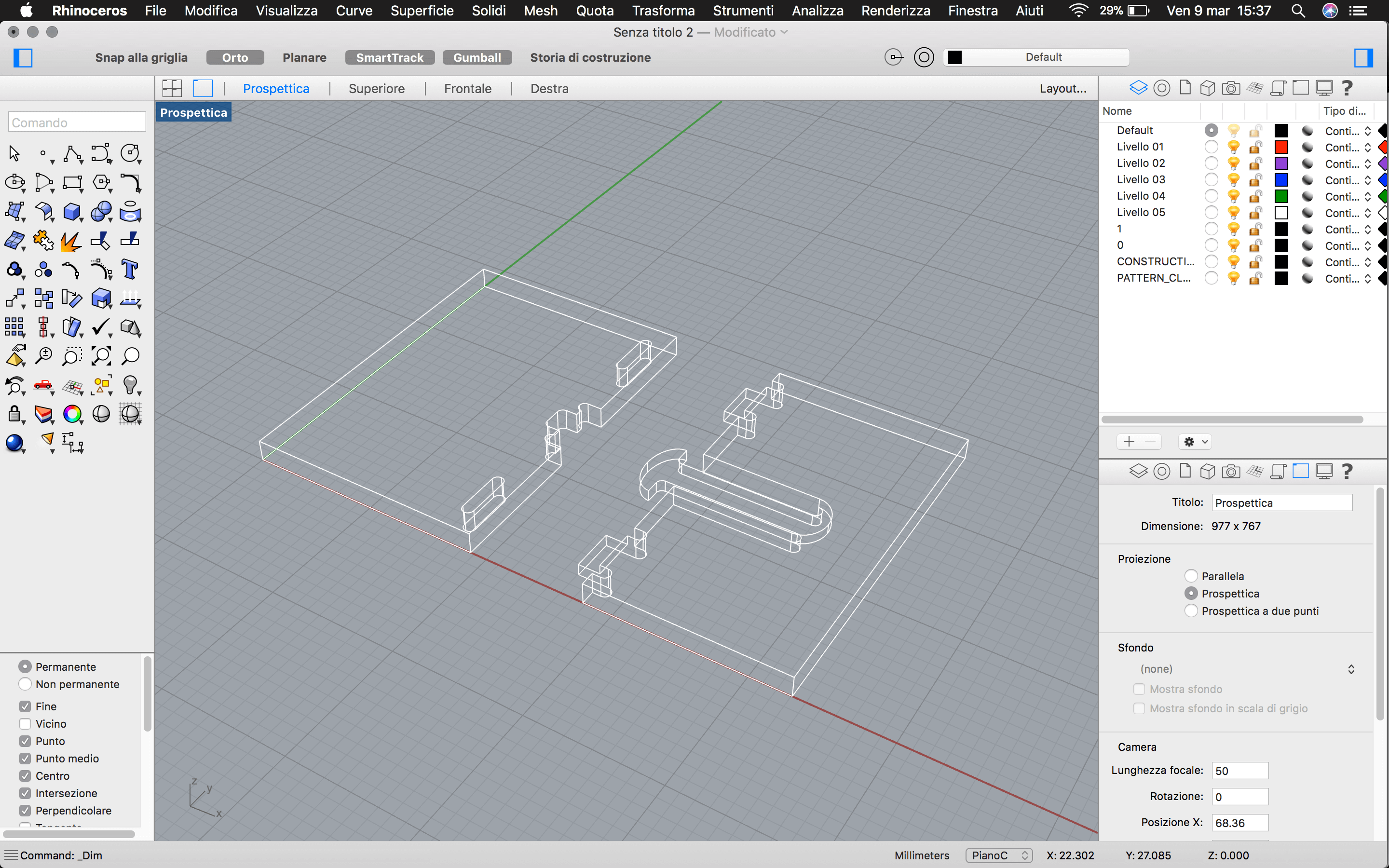
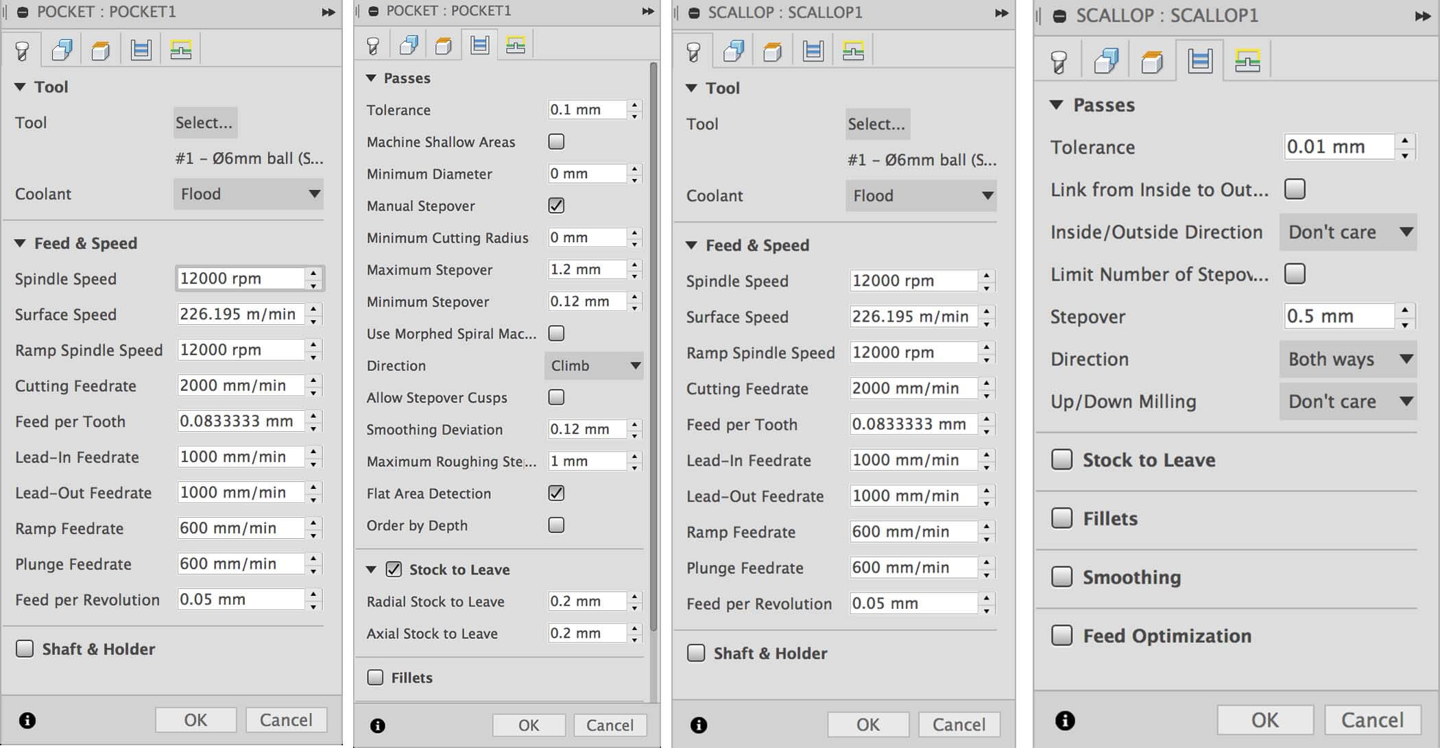
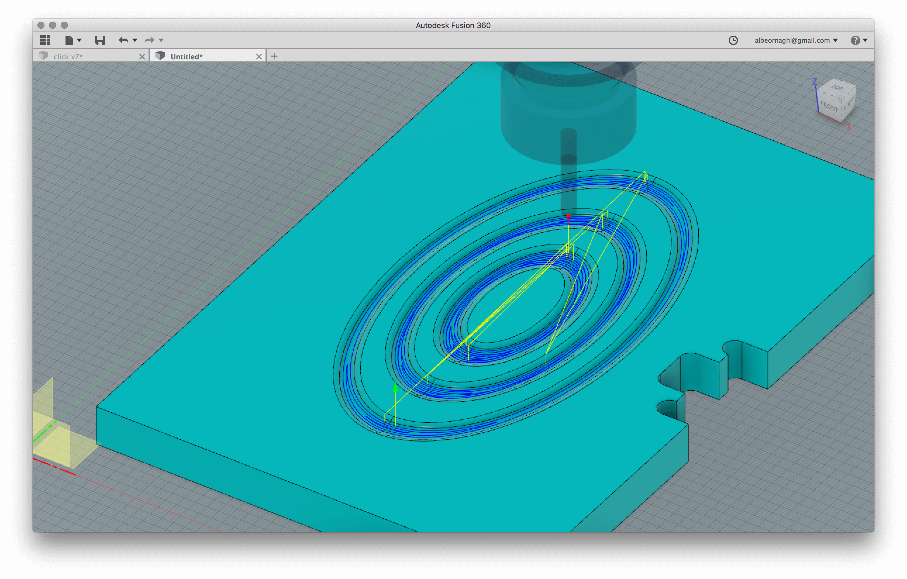
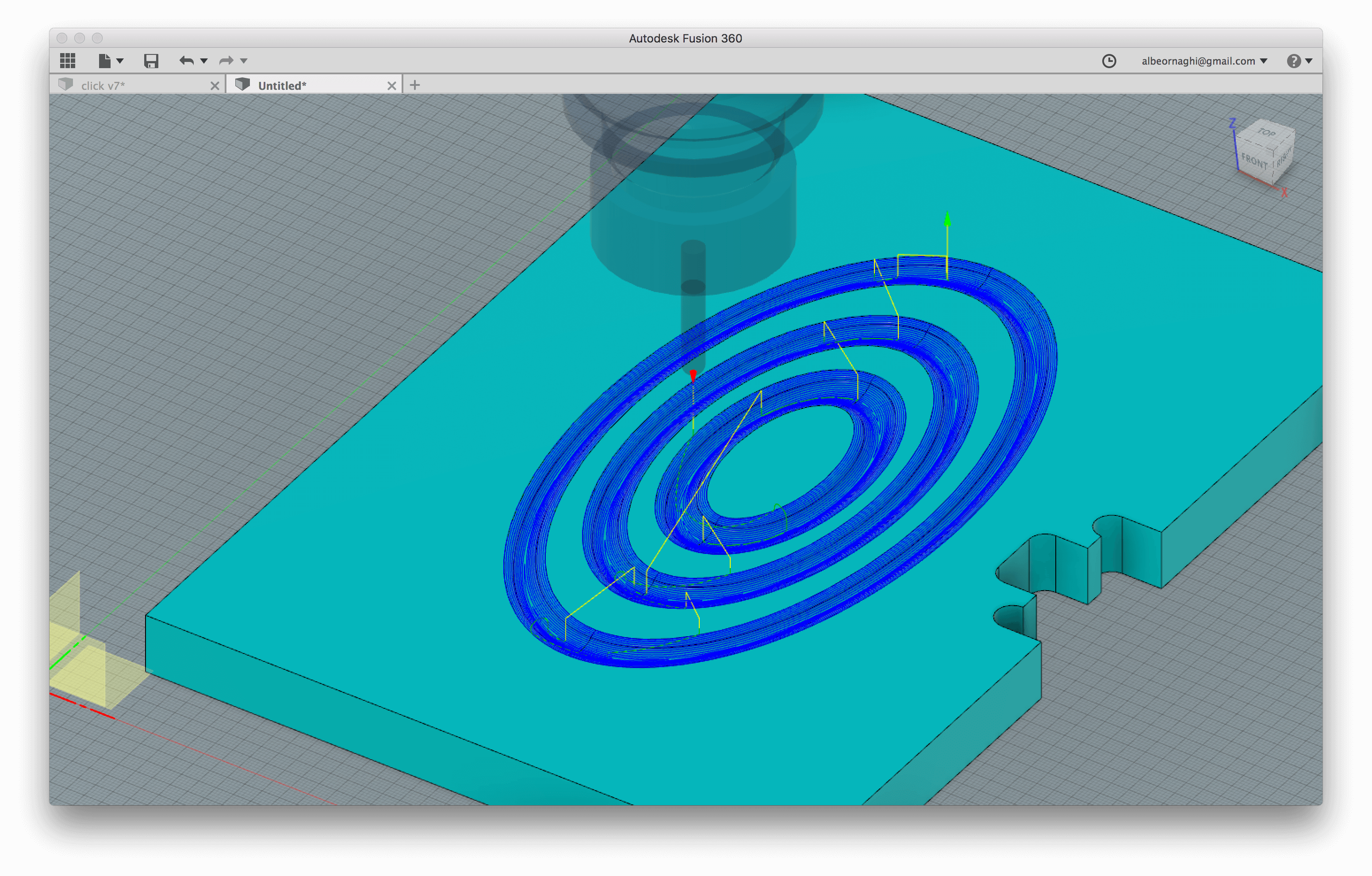
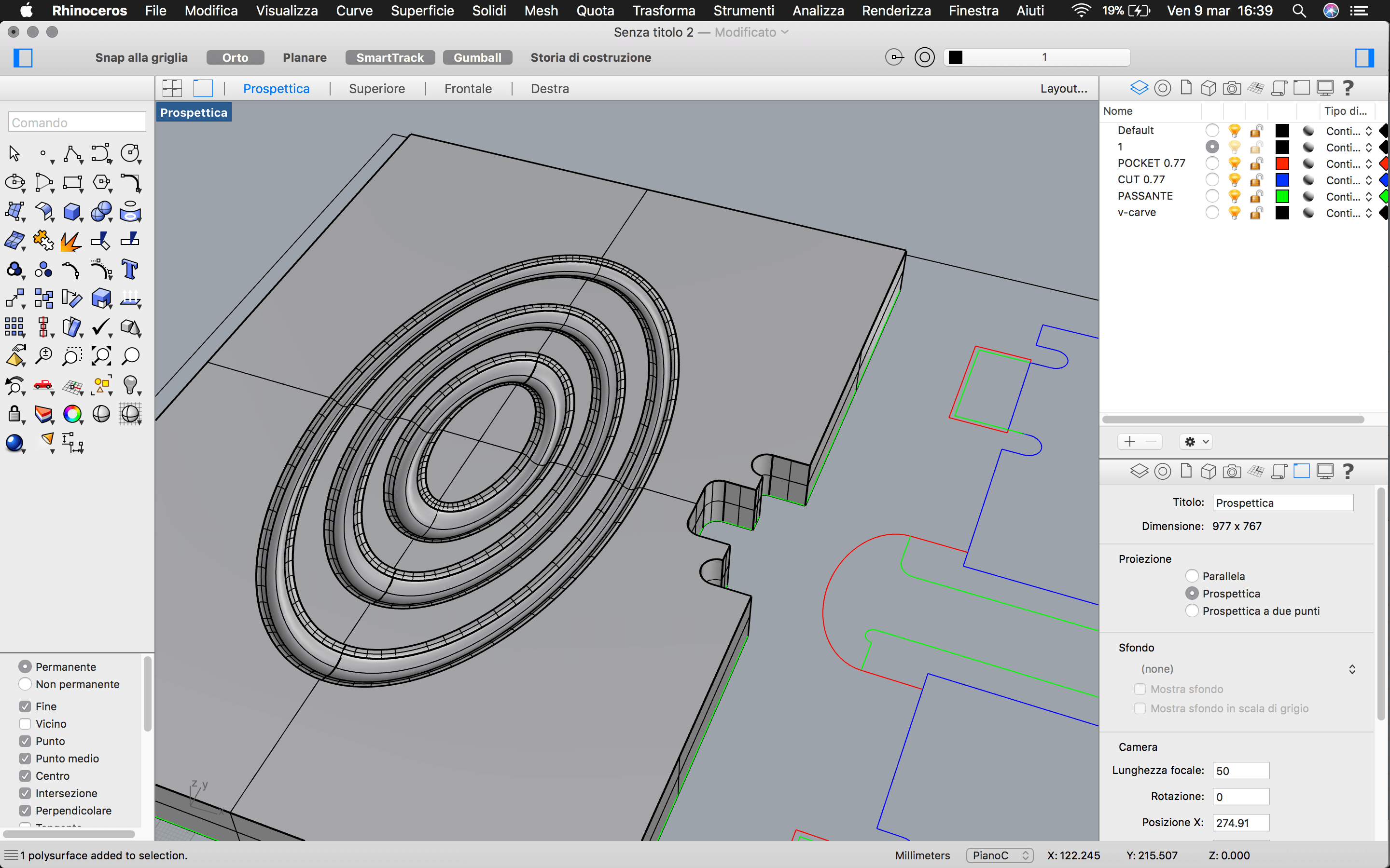 For testing the 3D milling we drawing in Rhinoceros three ellipsoidal "waves" on one of the two part of the joint. For 3D processing we imported the model in Fusion for try the CAM part of this software.
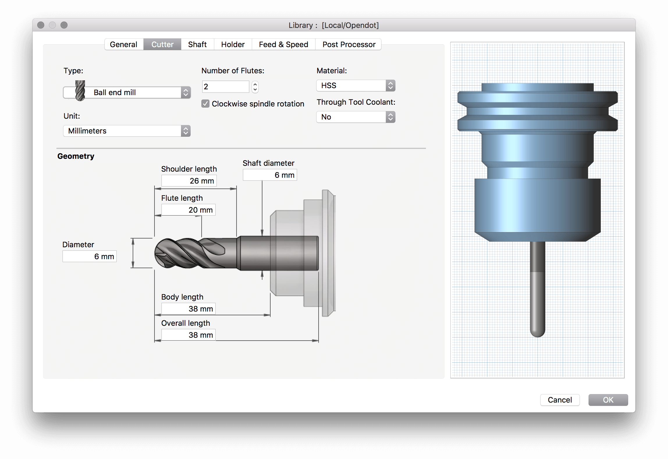 We selected a spherical tool 6mm diameter with 2 flutes, 12.000 rpm Spindle Speed, and 0,5mm Stepover.
 Simulation:
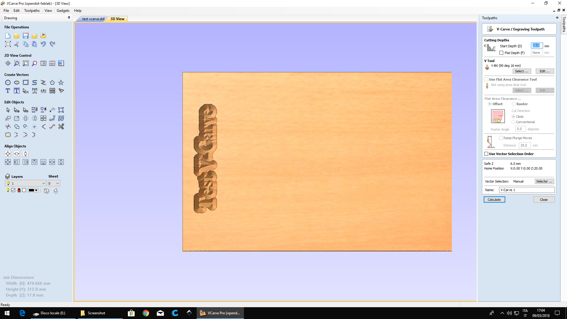
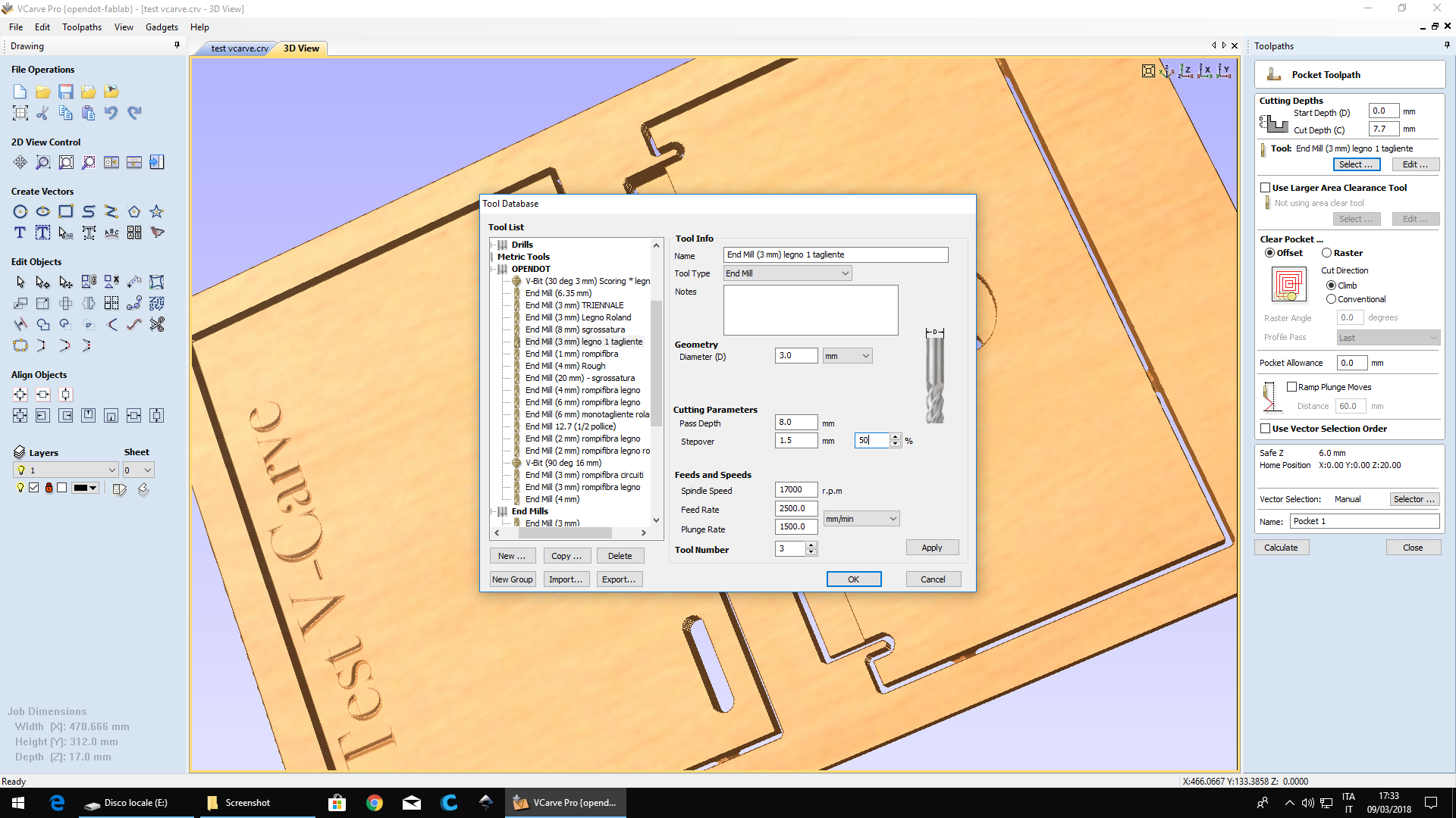
 Then we opened the dxf files on V-Carve and setting origin and the dimension and thickness of selected board of OSB wood.
For v carving text, we setted a V-shaped 90° tool with 10 mm cutting width and 6 mm shank and 2 flutes.
Then we opened the dxf files on V-Carve and setting origin and the dimension and thickness of selected board of OSB wood.
For v carving text, we setted a V-shaped 90° tool with 10 mm cutting width and 6 mm shank and 2 flutes.
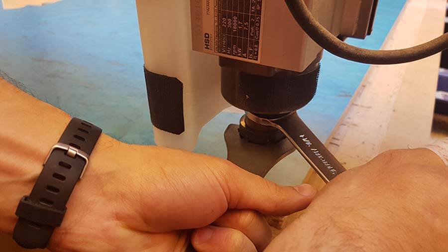
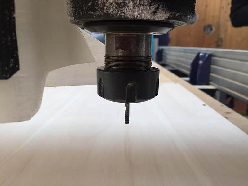
 Massimiliano change the cutting tool of the machine with Alberto.
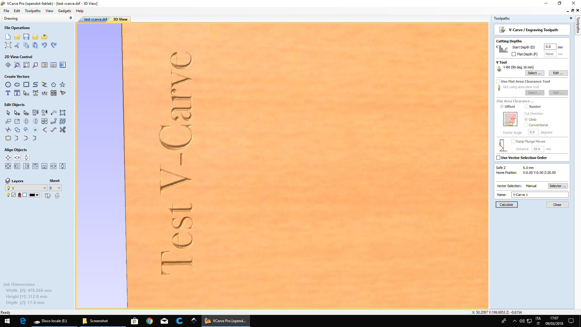
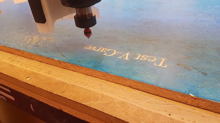
 Start with V-carve.
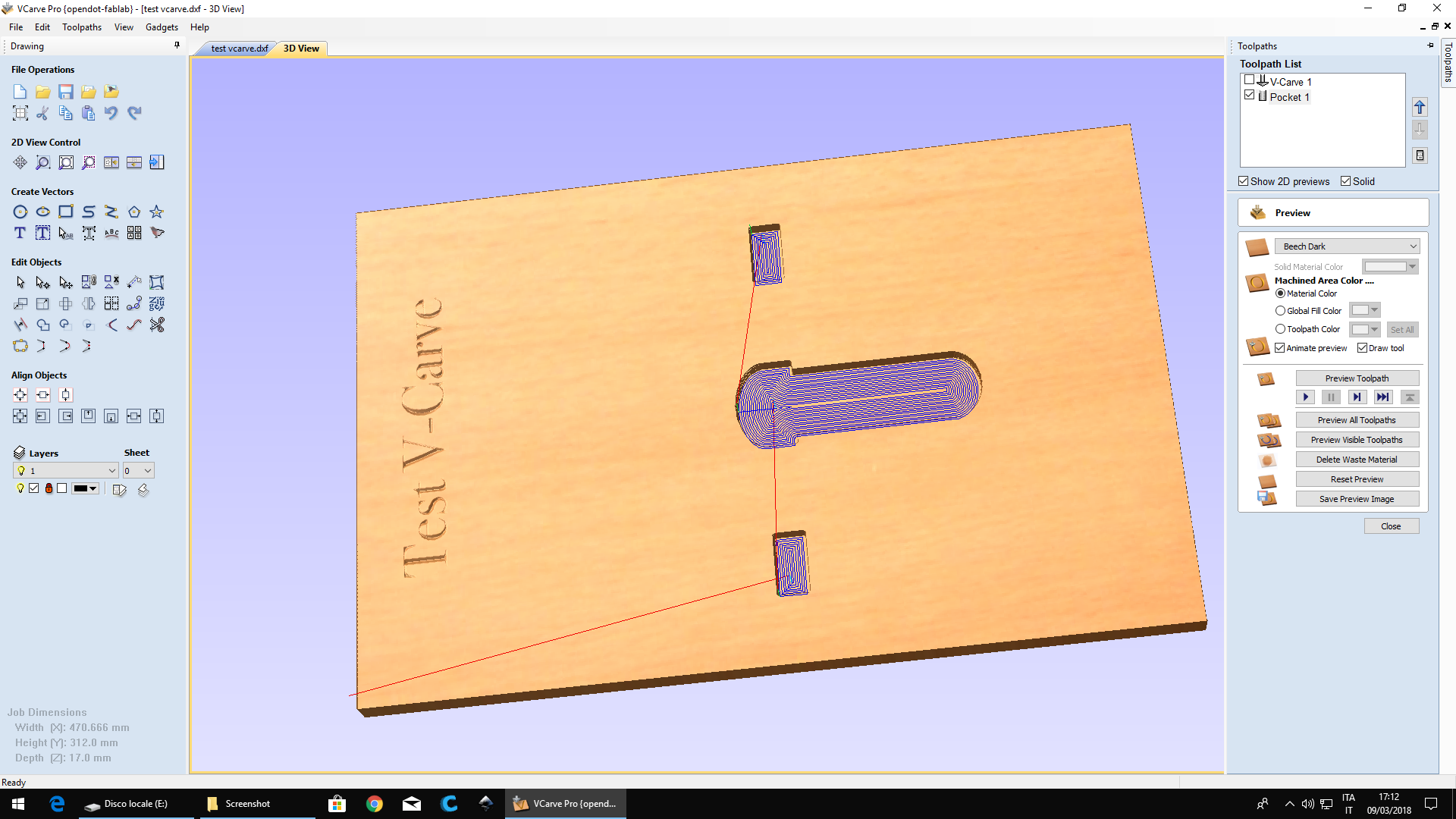
 Then: the pockets and outline cutting.We changed the tool with the flat one by 3mm diameter.
 At the end we upload the CAM of 3d "waves".(We changed the tool and put inside the machine a spherical one with 2 flutes.)
V-carve vs Fusion CAM
For 2d milling for me (that drawing in rhinoceros) it's more simple to work with v carve: it's faster and intuitive. Fusion cam is much more performing: the types of processing are many and very different. There is a bit of attention to be done during the import and export phases but it is certainly a free and very complete software that is absolutely worth using for 3D machining (see molding and casting week).
Make something big
I spent a lot of time deciding how to make my object for this exercise.
I decided to start giving shape to the container of my final project.
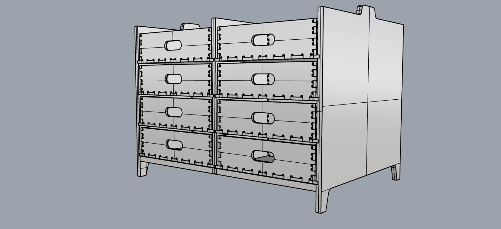
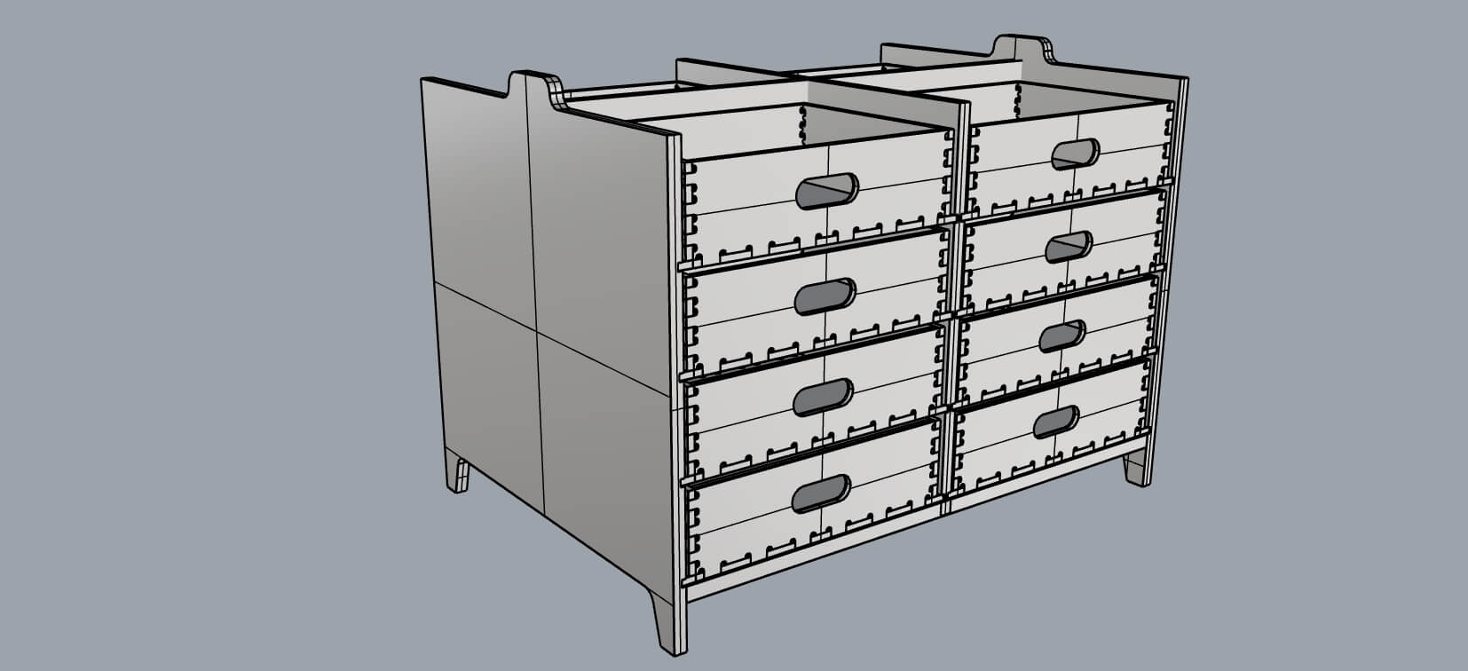
This "brainbox" (for now it's called brainbox because it contains the "knowledge" of fabkit) will be a wooden chest of drawers with different tutorial materials inside. Above there will be a body that will contain RFID and thermal printer, this part was designed by Francesco who works with me on the project.
This is very difficult to understand because many of the things it has to contain have not yet been decided. To the initial sketches you see on the page of my final project page the idea has been very modified, in the contents and consequently in the form.
But the real problem was that this technology has so many beautiful possibilities that I wanted to try them all before choosing the one to use. Perhaps, by the end of the course, I will have time to change my mind and try other solutions.
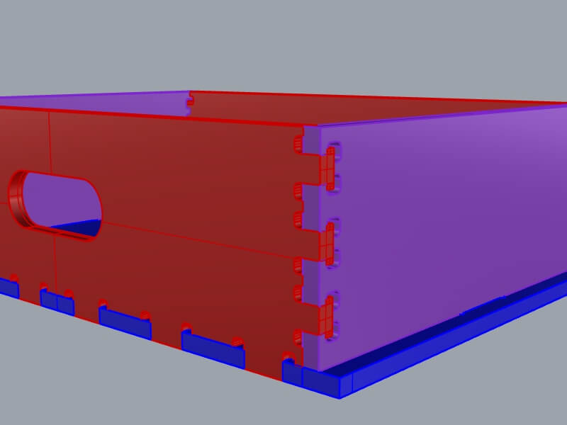
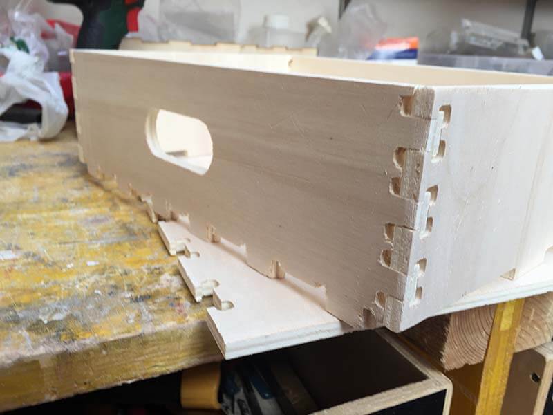
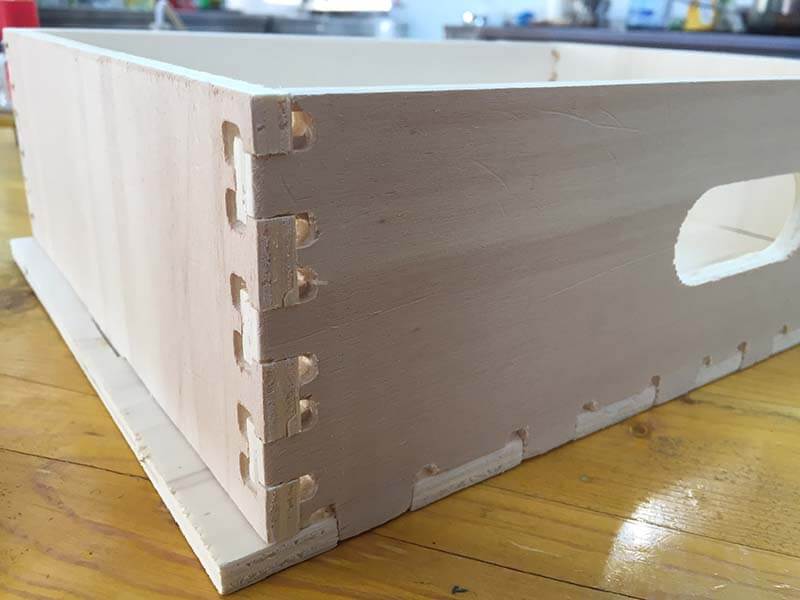
For the moment after a bit of research I chose this type of joint that was useful for making the drawers of my final project.
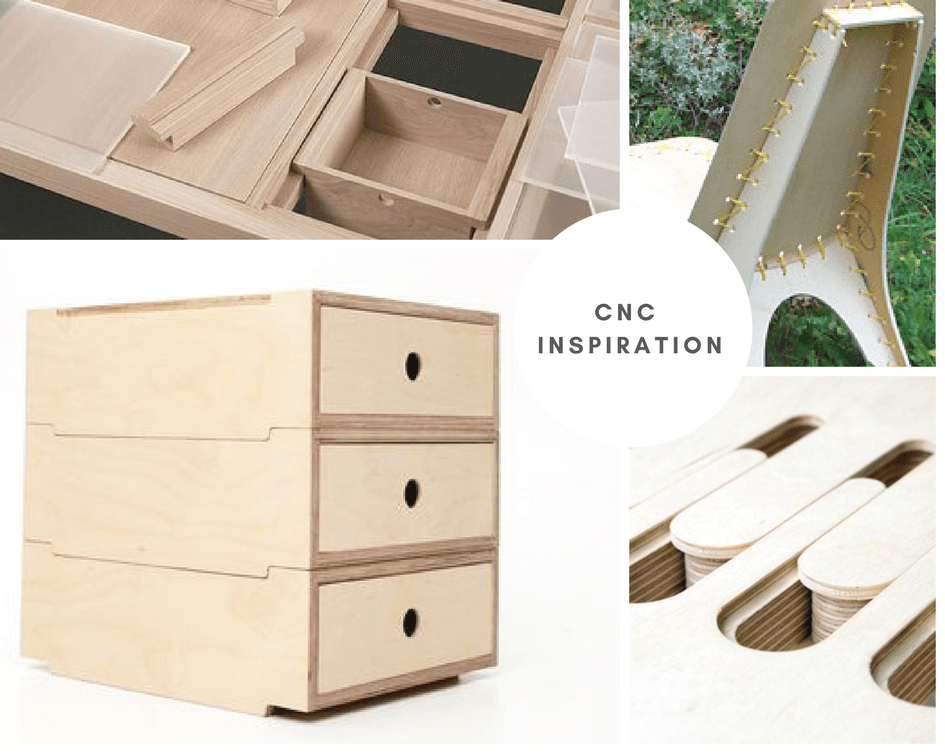
The things that inspired the final form are different. For now it is a mix of solutions that will have to be refined to have its own style.
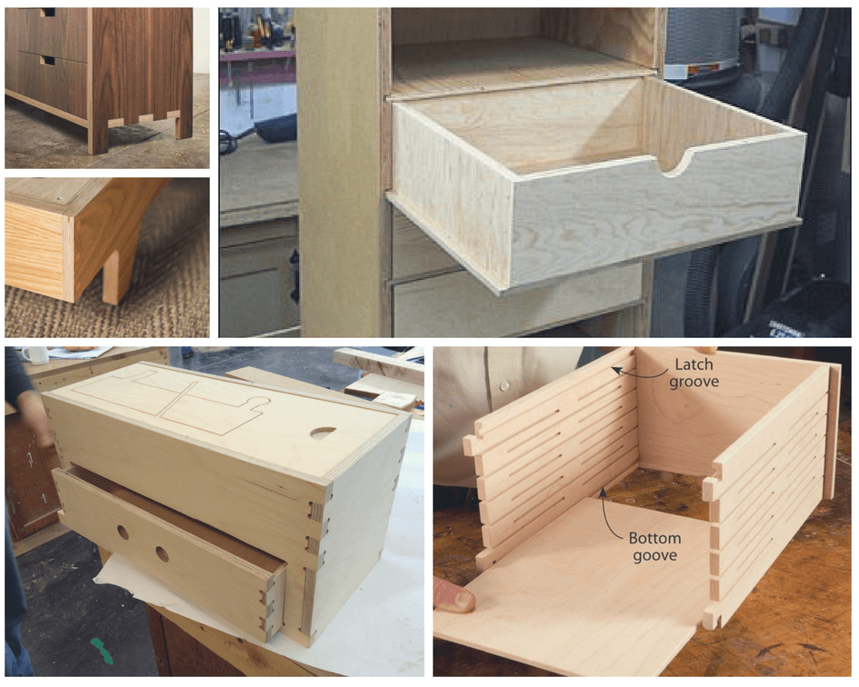
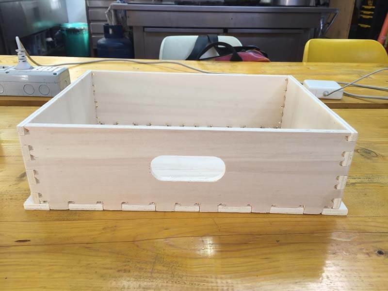
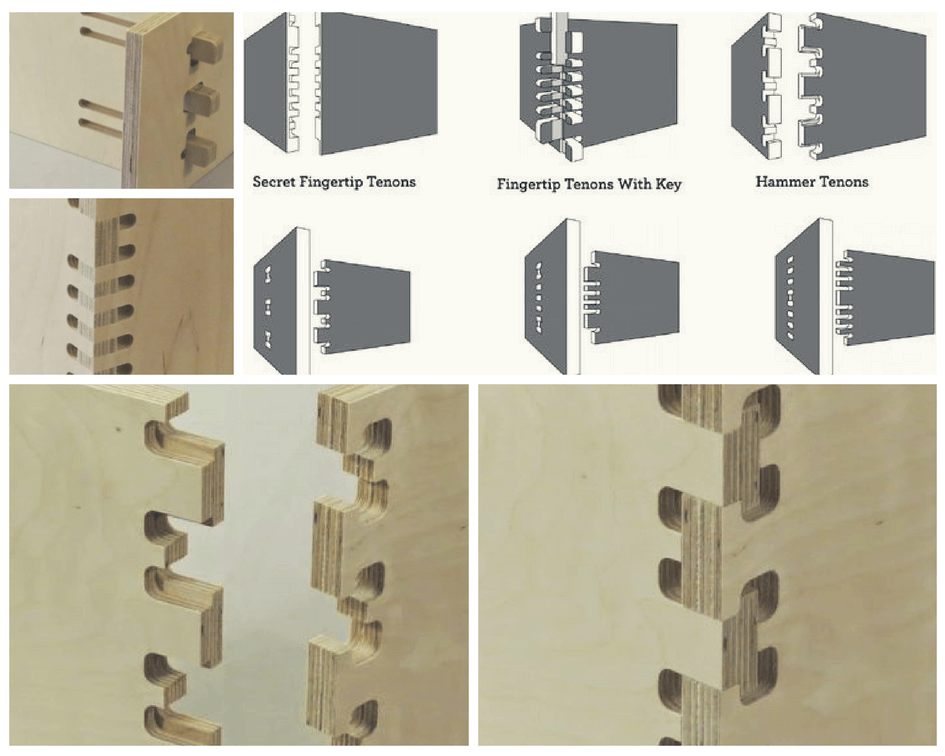 I chose this specific joint because it allowed me to keep the front of the drawer "flush" and to be able to position the handle to open it without risking it breaking.
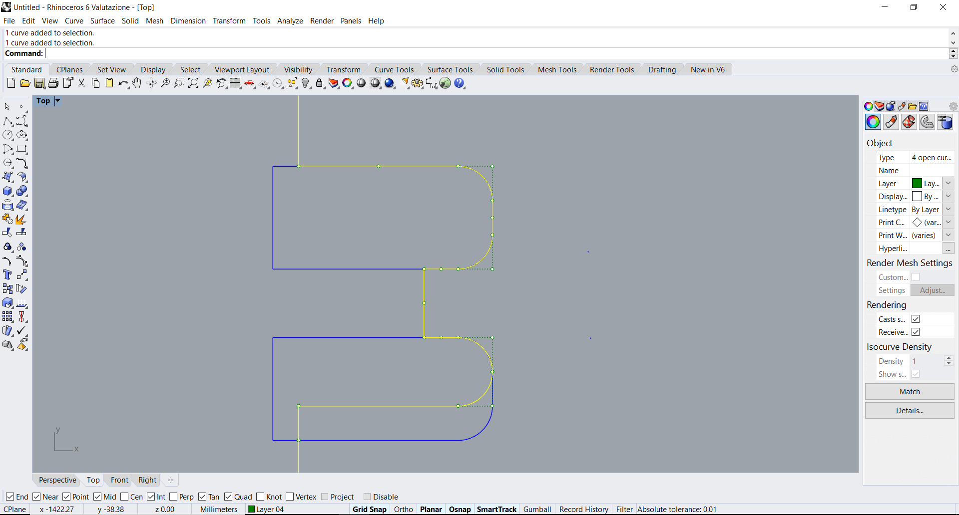
 I decided to mill the first model on a multi-layer 8mm thick wood. I design it in Rhino for now.
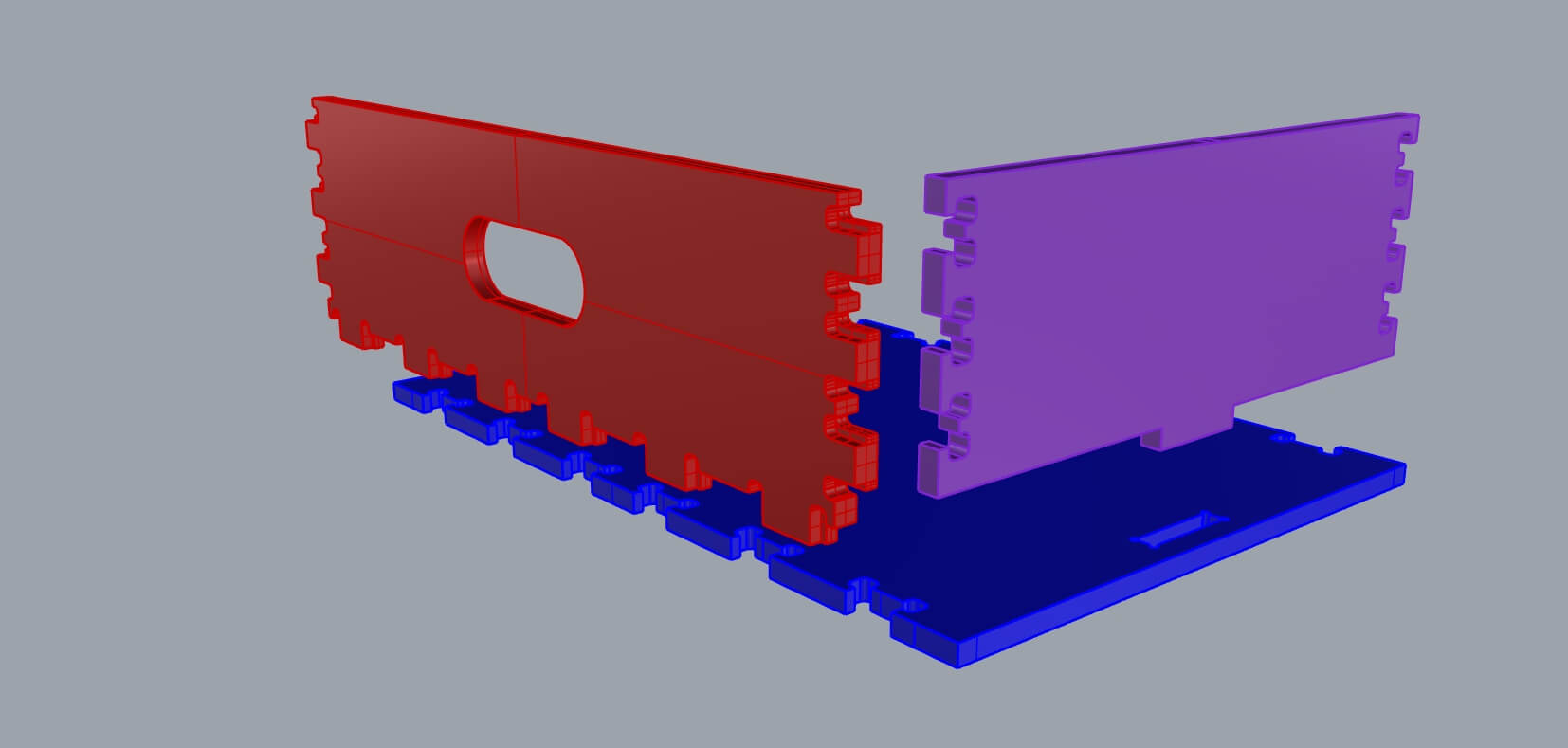
I re-design the joint for my tickness but
afterwards I discovered that in the laboratory at the moment there was not a milling tip of 4 mm in diameter and that my joints were perhaps too big. I lost half a day trying to get everything back but I could not, so I know that today the file can be optimized based on this parameter.
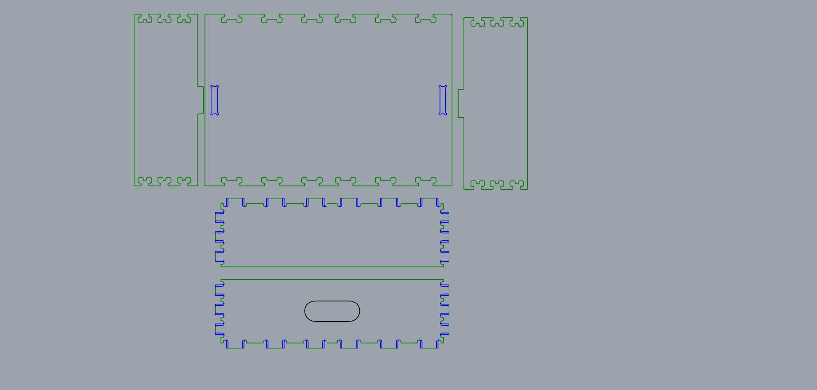
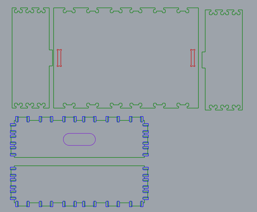
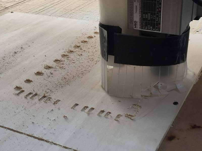
FATAL ERROR!!!!This passage is quite delicate: it is advisable to make the pockets a little wider than those used to obtain a little tolerance and facilitate assembly.
The first time I cut the wrong size of the pockets (green) compared to the cut (blue) and so when I cut I removed the pocket!
 If divided levels by color before exporting to dxf, it's much easier to select v-carve processing.
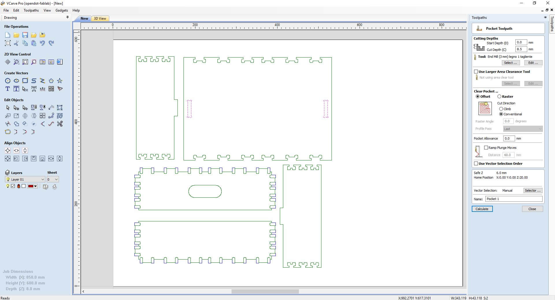
Import in v-carve, select parts for same processing.
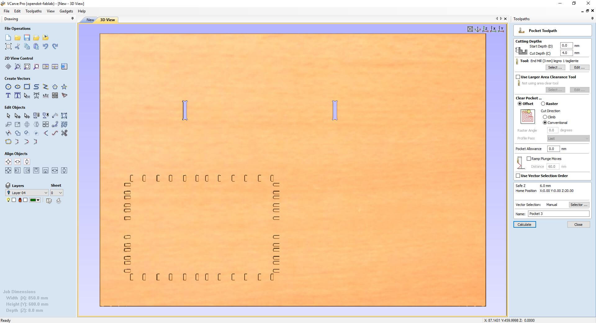
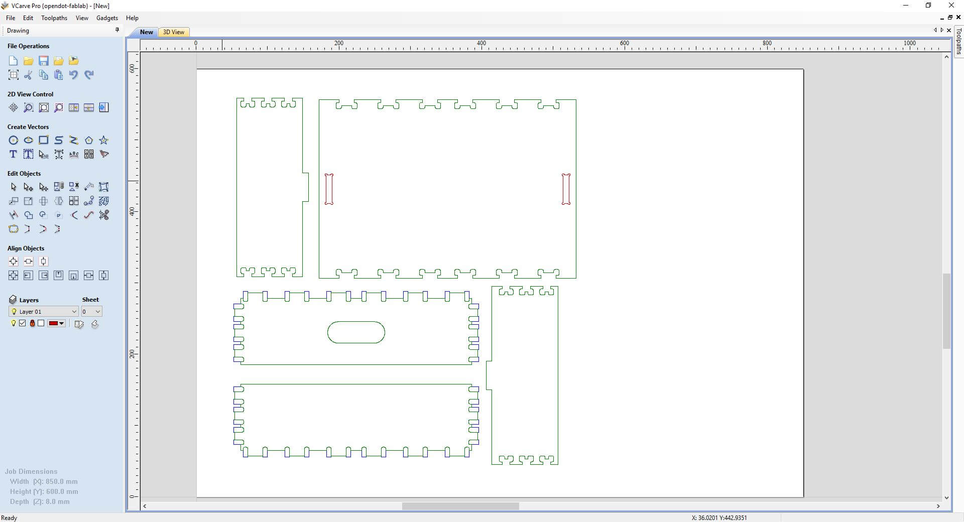 In this case I selected 2 pockets and in the toolpath setting (on the right) I choosed cut depth: 8.5, more than thickness (wood thickness: 8 mm) and End Mill (1 cutting edge 3 mm diameter).
 Then I chose the pockets, to do with the same tip, in a thickness of half the wood, with a little 'of abundance to facilitate assembly. For my final project I optimized the file that now contained too many joints.
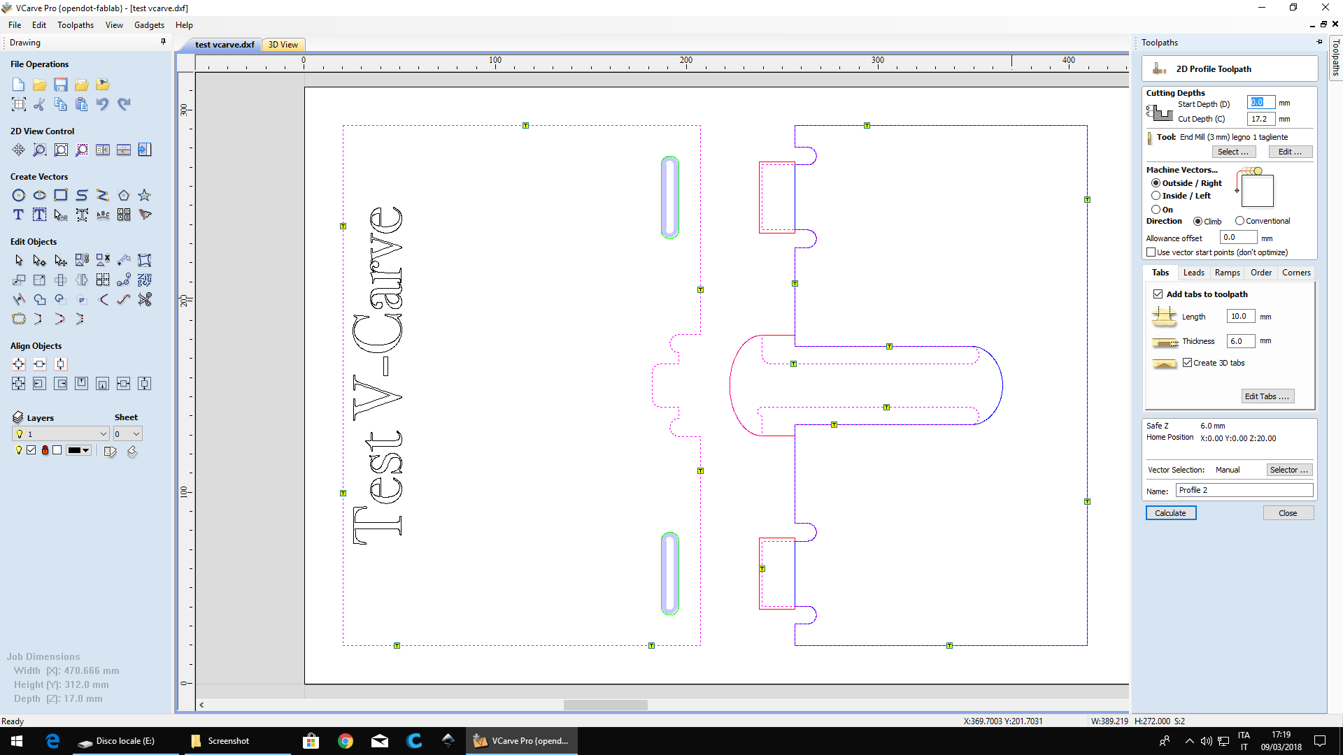
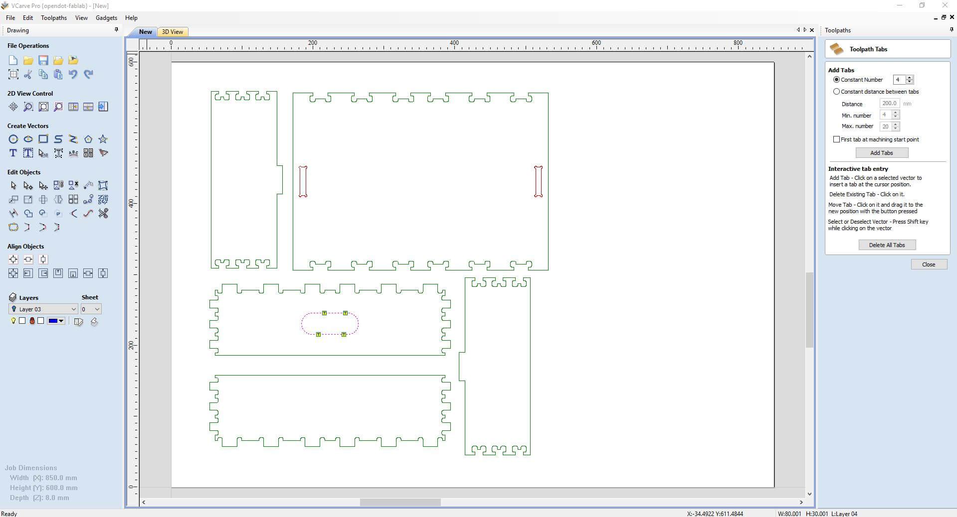
 Inside the machining of the profiles (cuts) v-carve allows us to set the "tabs" to avoid that the piece is detached during processing.
you can set the parameters of thickness and size, choose the position that works best depending on the piece. the removal could leave some defects.
Inside the machining of the profiles (cuts) v-carve allows us to set the "tabs" to avoid that the piece is detached during processing.
you can set the parameters of thickness and size, choose the position that works best depending on the piece. the removal could leave some defects.
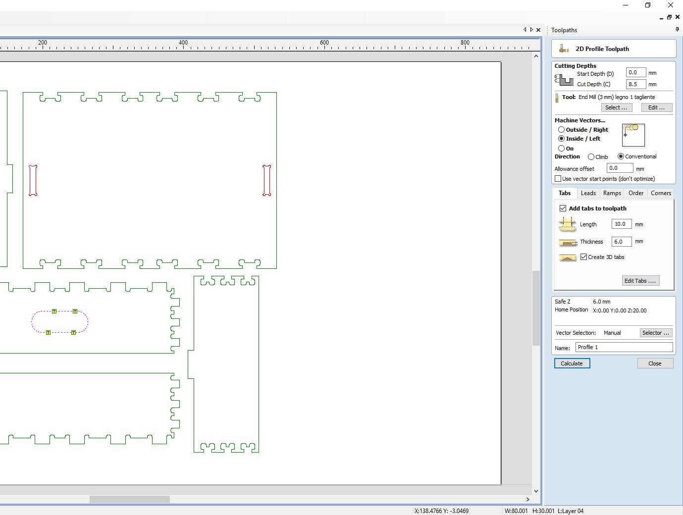 The same process is important to do it also for the final contour of the piece (which is usually the last cut).
 Once all the toolpaths have been done, they can be exported individually or together. For safety I export them individually, so that the machine can be stopped between one and the other for any maintenance operations, tip changes, resetting, but also because if you had to break the tip on a long process it is more difficult to recover work compared to a short process.
 For the preparation of the cnc milling machine, after the file was exported (piece positioning, zeroing, etc.) I followed the same procedure described in the group assignment.
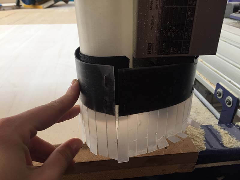
 This is an experimental object of our fablab that serves to convey the air of the aspirator, it does not work very well.
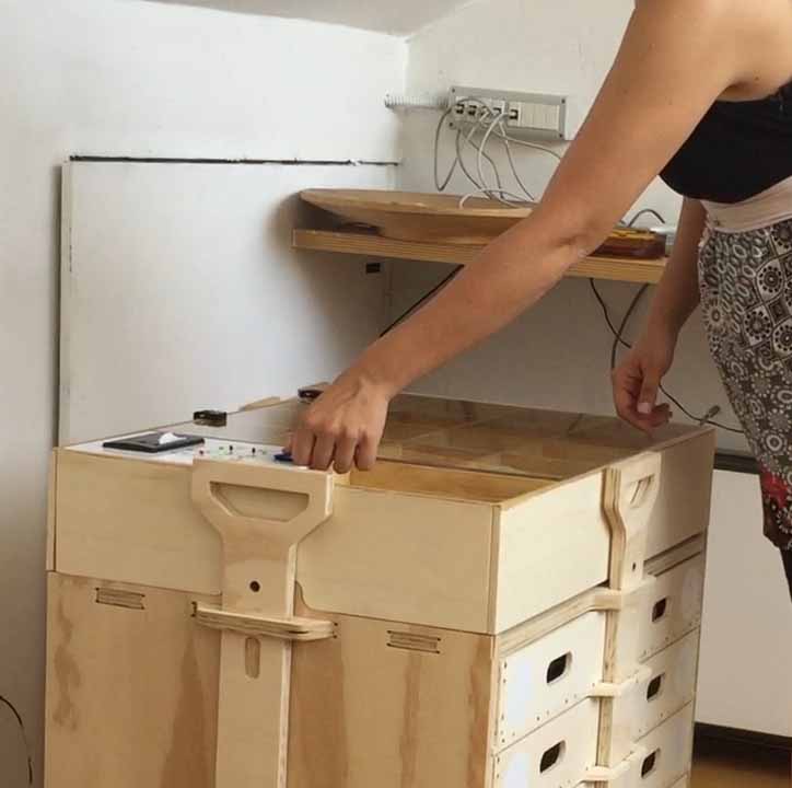
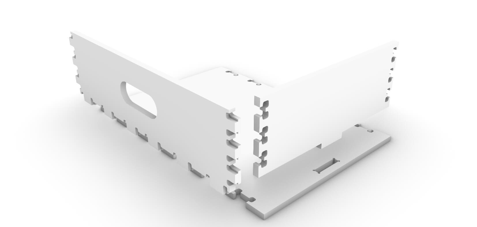
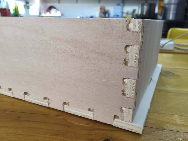
 And here is the final result. The assembly with all the joints is not easy, for the final project there will be a review of the file to optimize the time.
These drawers will be contained inside a chest of drawers, here a first version of the model, you can see how the final result came in the Project Development Page of this site.