Computer-Controlled Cutting
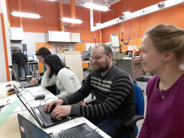
Group members
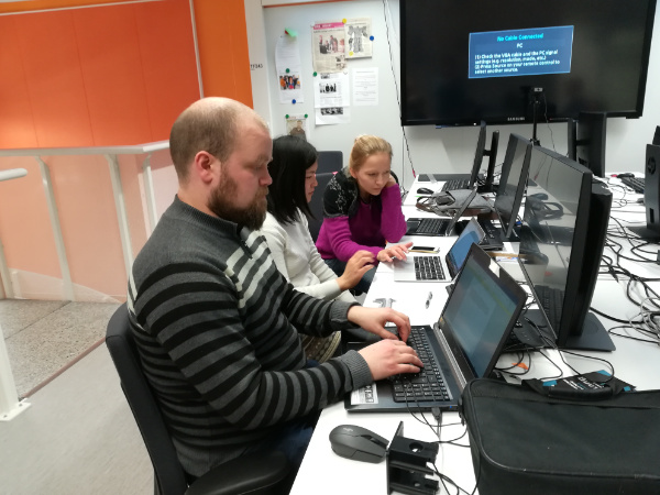
Planning and Preparing
We first decided a time that was suitable for all. And after the introduction from the local instructor, we started to plan how would we proceed. We asked Eino how did he do it last year, and we used that as an starting point. We thought together how to proceed: we would draw some pieces that we will afterwards cut with different parameters and in at least two different materials. The plan was to engrave in each piece the settings we would use to cut each piece.
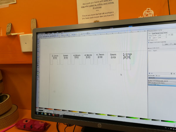
Megumi started to draw the designs while we together discussed the different sizes we would need in order to better determine the Kerf of the lasser cutter, Ari started to write a document to describe what we did and Marta started an excel document to write and later share with all. We all decided the pieces to be 10mm wide, having the male pieces a tooth of 5mm or 5.1 mm, and the female pieces slots of width 4.7mm, 4.8mm, 4.9mm, 5mm and 5.1mm. Soon, Kati started to prepare the laser cutter to start cutting. We would start with Acrylic 3mm, and the default values for speed, power and frequency. We would then vary the speed. And later, do the same with MDF 3mm.
Cutting and Measuring
We went to the laser cutter, and we made sure that both the ventilation and the air pressure were open. We started to prepare the machine for acrylic cutting first, setting the focus and the origo.
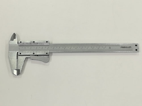
We had two Vernier calipers, one digital and one analogical. We planned to tyake measurements with both
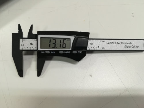
Out initial plan was to measure the slot of each female piece (5) plus the tooth of the male pieces (2) for each of the 10 different settings we planned. But when we started to use the calipers we realized it was going to take long time. What we ended up doing is measuring the outer part of two different pieces.
We measured both with the analog and digital caliper. Megumi and Kati meassured while Marta was writing the data and Ari was describing the process. When we later checked the data, we decided to just keep the data from the digital caliper, as the other data differed a lot from average values we could find in the internet or from last year projects.
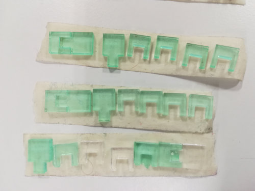
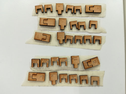
The pieces we cut:
Data summary
Marta created some summary tables with the data. The outer pieces should be 10mm. So calculatingKerf = 10mm-ValueMeasured
| S6 | S8 | S10 | S12 | S13 | S15 | ||
|---|---|---|---|---|---|---|---|
| Acrylic 3mm (P100,F100) | |||||||
| piece 1 | 0.2 | 0.17 | 0.09 | NO CUT | - | NO CUT | |
| piece 2 | 0.22 | 0.13 | 0.12 | NO CUT | - | NO CUT | |
| MDF 3mm (P80,F20) | |||||||
| piece 1 | - | - | 0.18 | - | 0.16 | - | |
| piece 2 | - | - | 0.16 | - | 0.14 | - | |
| MDF 3mm (P100,F100) | |||||||
| piece 1 | 0.2 | 0.2 | 0.14 | - | - | - | |
| piece 2 | 0.15 | 0.15 | 0.15 | - | - | - | |
What we did with the female/male pieces was to test how well one fitted to another. We matched the best case for each combination of material+settings and we got the following values, represented as male[mm]/female[mm]:
| S6 | S8 | S10 | S12 | S13 | S15 | ||
|---|---|---|---|---|---|---|---|
| Acrylic 3mm (P100,F100) | |||||||
| piece 1 | 5/4.7 | 5/4.7 5/4.8 | 5/4.7 | NO CUT | - | NO CUT | |
| MDF 3mm (P80,F20) | |||||||
| piece 1 | - | - | 5.1/4.8 | - | 5/4.8 | - | |
| MDF 3mm (P100,F100) | |||||||
| piece 1 | 5/4.7 | 5/4.7 | 5/4.7 5.1/4.8 | - | - | - | |
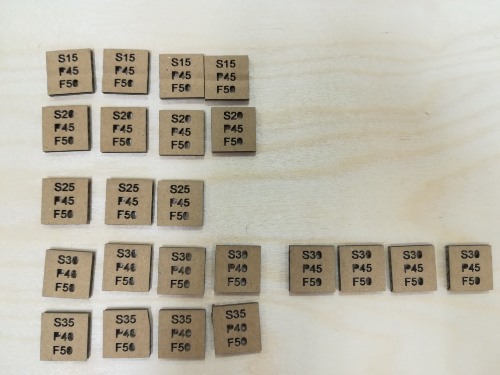
Kerf = (Male[mm]-Female[mm])/2As Megumi was planning to use cardboard in her pressfit project, she decided next day to cut some cardboard squares with different values and meassure them. These are the values:

Field notes
These are the notes Ari wrote:
We started to create different puzzle parts, where we test different values on the male and female parts.
Megumi started to work on the Inkscape to create the parts and Ari started to document the process.
Marta wrote the different sizes in the Excel. Kati found average kerf values for different materials and we
decided to compare them against our own results.
The parts are presented in figures. For the cutting we used the lasercutter Epilog Laser Fusion 75 W. Kati,
Marta and Megumi had used the lasercutter before and taught Ari the use of the machine. Ari started to
work as an operator, so he could learn to use it as well. The first test we made with 3 mm acrylic. The laser
was focused on the part and the origo was set in the upper left corner of the material. The cutting program
was set with a pdf file and we started to cut the material. After each cut, we changed the origo position to
follow the last one and switched the program. In the cutting programs we changed the speed value and
controlled the cutting with only that setting. The power and frequency were kept at 100 % in all the cases.
The acrylic started to show flames when the speed was 6 %, the recommended value in the lasercutter was
8 %, but we found in the manual that the value for the 3 mm acrylic should be 15 %. The problem with the
recommended value was, that laser didn’t go through the material and the same problem was with 12 %
case. 10 % was the value where it was hard to remove, but still went totally through. The second material
was MDF 3 mm. Our parts were so small that in the case of MDF the parts started dropping through the
mesh and we had to ”fish” them through the mesh after we finished cutting.
The best fit for the pieces is between the 5 mm and 4.7 mm with both materials. It seems that the best fit
was universally between the 5 mm and 4.7 mm pieces. The 5.1 mm piece broke the 4.7 mm piece, so we
can say that it was too big and required too much force to make them fit. The joint parts are measured with
caliber to find the accurate value for the thickness. We chose to change the value in the female pieces, but
it would have been easier to measure, if we changed the male pieces.
After a little bit of thinking, we decided to make the measurements from the outer side of the pieces. The
kerf would be the half of the difference to the given value 10 mm. We chose the corner pieces for the
measurement. The kerf changes with different materials and different settings and the caliber also affects
the results. We had two different calibers and we could see clearly the difference between the tools. The
difference was systematic and always in the same direction. To consider how the position affects the kerf,
measurements were also done with different pieces in the same test set. The documentation and
measurements took a lot of time, but we wanted to be thorough with the given task.
If we had to start from the beginning, we would change the male pieces, because we couldn’t measure the
kerf easily from the female pieces.
We decided to create a simple webpage for our project and present our results there. The files for the
cutting and results are shared.
Conclusions
- Clearly the kerf depends on the material
- The kerf depends on the speed (decreases with the speed)
- The values are clearly orientative. Test always first!!