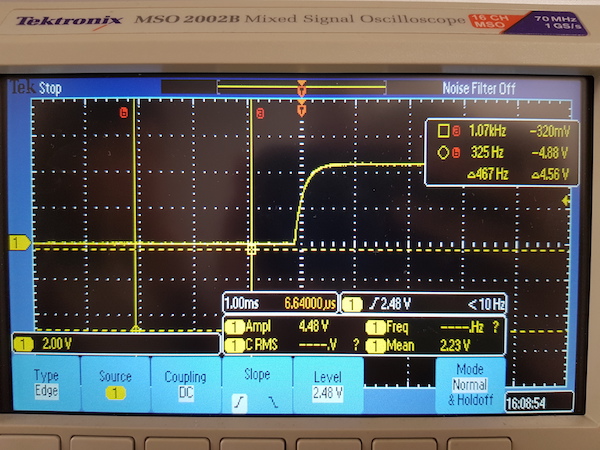
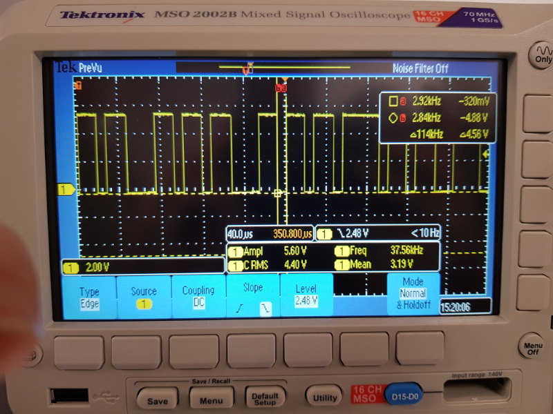
Without filter
This week amonside of designing electronics, we were supposed to use the test equipment in our lab to observe the operation of a microcontroller circuit board.
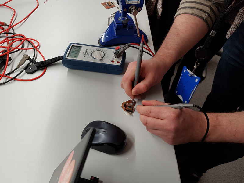
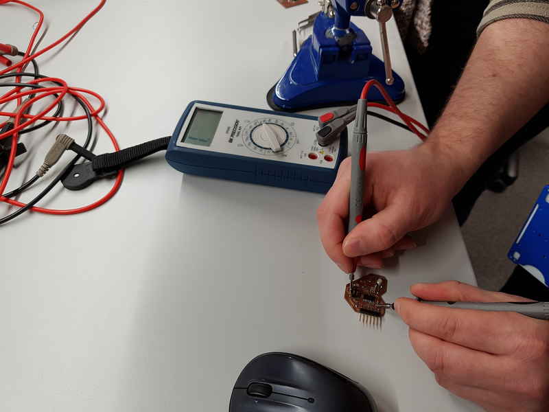
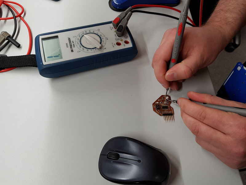
We started to test our board with multimeter. We set it to beep mode, which means that it makes a sound, if the connection is formed and short circuits can be found. We tested all the connections and started with the most crucial, VCC and GND. There was no short circuit there, so we moved on to other connections and found no problems. We also tested button to see that it created the connection and it created the "beep", when the button was pushed.
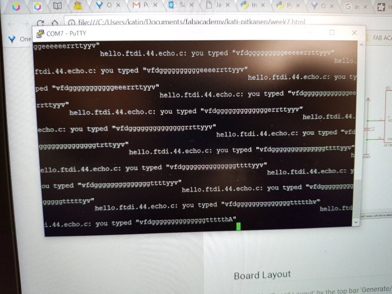
We all have managed to program, with the hello echo program, the board we had to design and build for this week assignment. Our plan is to measure the signal received from the serial port in one of the boards when pressing the key in the keyboard.
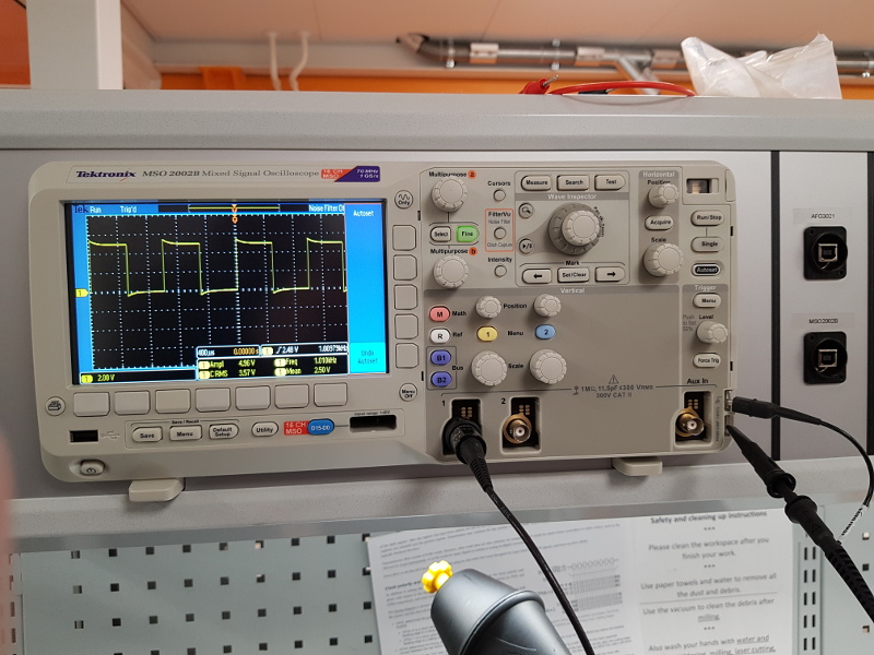
First, we check the oscilloscope callibration signal by putting the probe in the connectors for that. We thought the signal was good enopugh for our purposes.
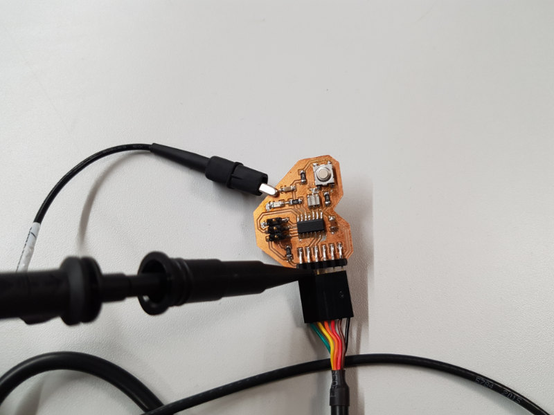
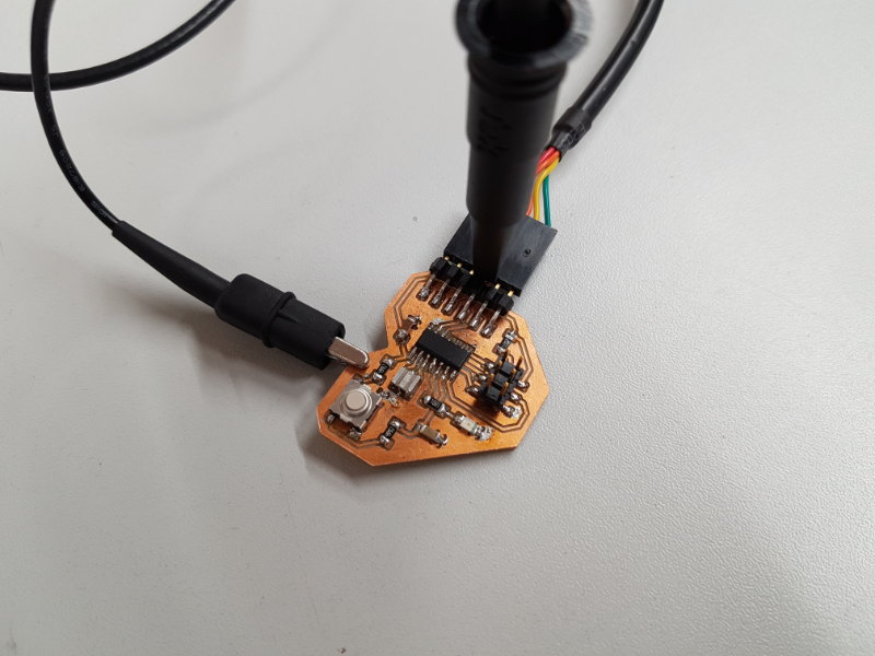
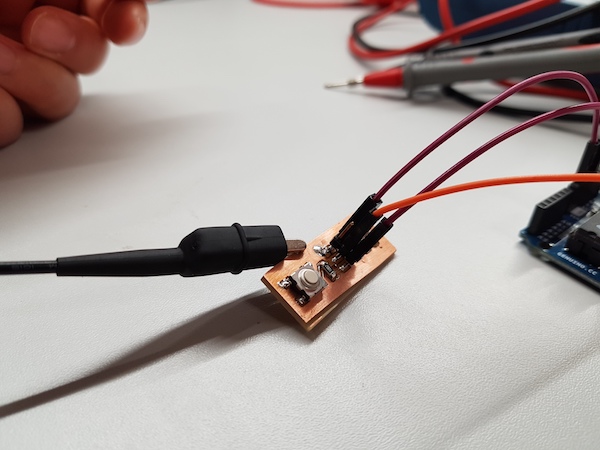
We measured the signal of the push button to see how filter for the button works. Antti Mäntyniemi suggested us to put filter for the push button on echo hello-world board. From his experience of previous year’s Fab Academy assignment, he found that when the push button is released, sometimes it makes unexpected glitches. To avoid this happening, he put filter using resistors and capacitor to make the falling and rising push button signal clear. We followed the advice and put filter for the push button on our board. As part of the group assignment, we measure how the filter works using oscilloscope.
The board demonstrates two patterns of the behaviour of the signal of the push button, with and without the filter. The filtered circuit uses two 10k ohm resistors and 10nF capacitor. The another circuit uses only one 10k ohm resistor. We changed the circuit by using jumper to connect the pin which goes to add capacitor and the resistor.
Here is the result. Without filter, the signal was sharp, but sometimes it gave us glitches when the push button was released.
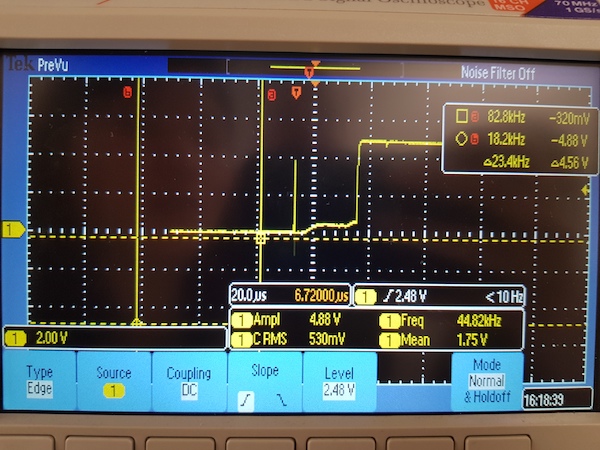
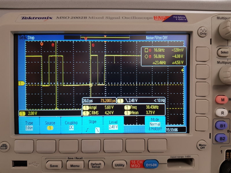
With filter, the signal was more gradual compare to the previous one, but the signal was clean without any glitches.