Input devices [Week 12]
Group members
Group assignment
Measure the analog levels and digital signals in an input device
Work description
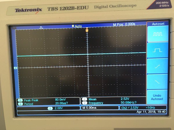
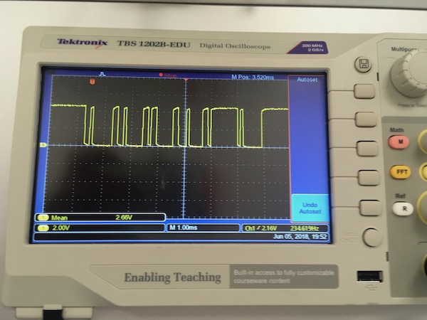
- We measured the analog signal from the hall effect sensor made by Marta Cortés. We used oscilloscope to see the voltage changes when the magnet comes close to the sensor.
We started measuring analog output of the sensor.
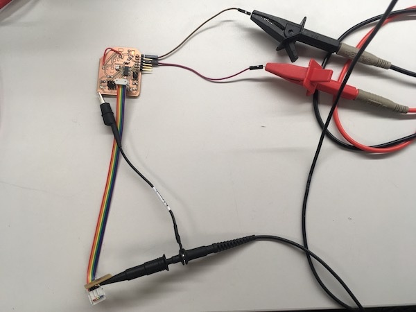
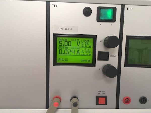
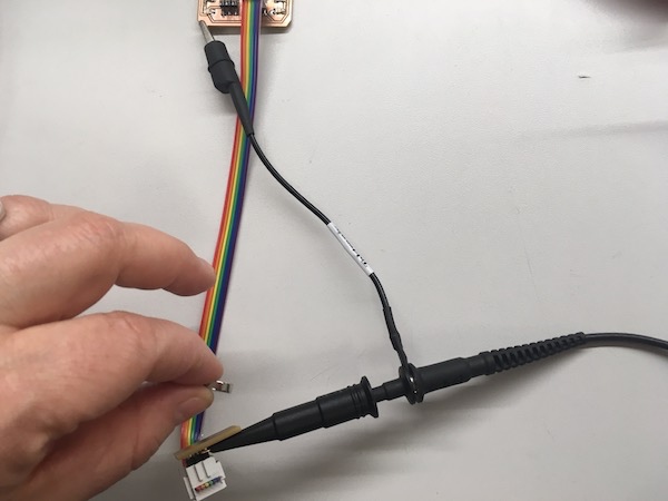
We connected the hall sensor PCB with oscilloscope to see the singal and with power supply to provide 5V.
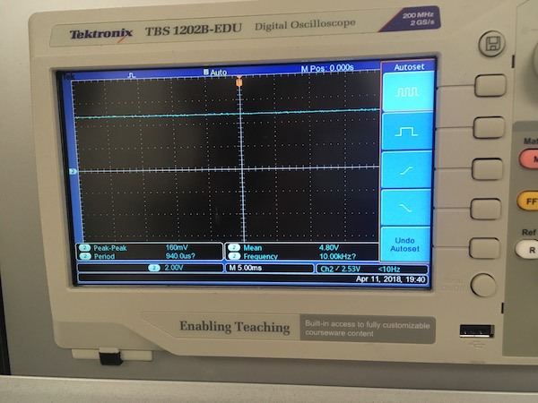
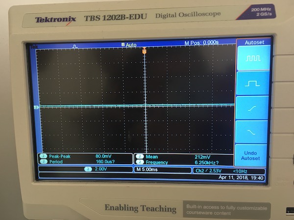
We brought the magnet close to the sensor and see the voltage changes. In normal situation, voltage oscilloscope measured was around 2.5V. When one side of the magnet was brought close to the sensor, voltage increased to 5V. When the other side of the magnet was brought close to the sensor, voltage dropped to 0V.
For measuring digitl signal, we measured serial output of ATTiny44 transformed from analog input from hall effect sensor to digital.
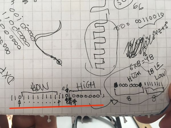
When the magnet came close to the sensor, we got following digital signal from oscilloscope.
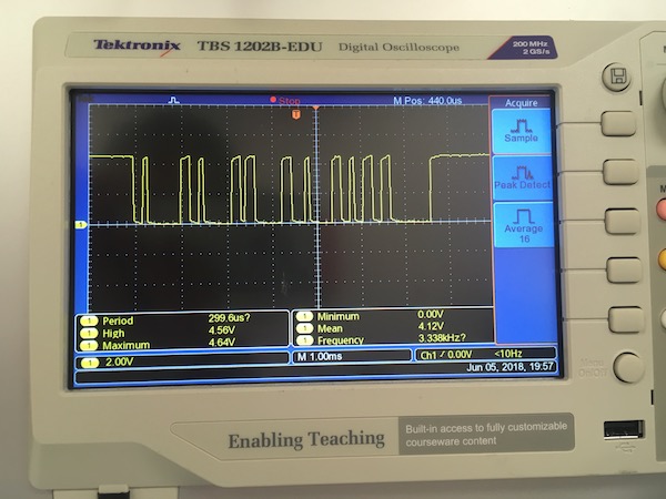
We clearly identified preamble and low and high values, which correspond to a value close to 0 as expected.
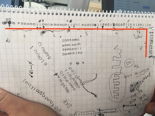
When the magnet was far away from the sensor, we got following digital signal from oscilloscope.
We also identified preamble and low and high values which correspond to 512.