Assignment: Group assignment: - Review the safety data sheets for each of your molding and casting materials, then make and compare test casts with each of them Individual assignment: - Design a 3D mold around the stock and tooling that you'll be using, machine it, and use it to cast parts
Group assignment
We started to learn about molding and casting at 9 am at 23.3.2018 with our local instructor Ivan Sanchez Milara. We studied the basics of mold making, milling of the mold and different types of mold and cast materials. We read the safety data sheets for each material and also read the instructions for their use. The group assignment is documented in the molding and casting group page. We had bad luck with Oomoo 25, because it had all gone bad (5 new packages) and the material itself was only 2 months old and sealed in the bottles. The whole shipment had gone bad and the material provider promised to send a new batch, but we were not sure, if it would get here in time.
Designing of the mold
I wanted to make a mold for a peristaltic pump casing, which is part of my final project, but since all of our Oomoo 25 had hardened and went bad, we had to use Smooth-Sil 940 for the molding and it had to be enough for everyone.
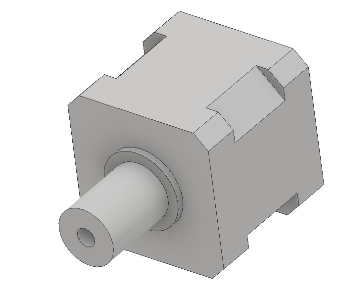
Basically it had to be something small and as the silicone was suitable for food related applications, I wanted to mold chocolate. I had made a 3D model of a stepper motor with adapter for my final project, so I decided to make a chocolate motor.
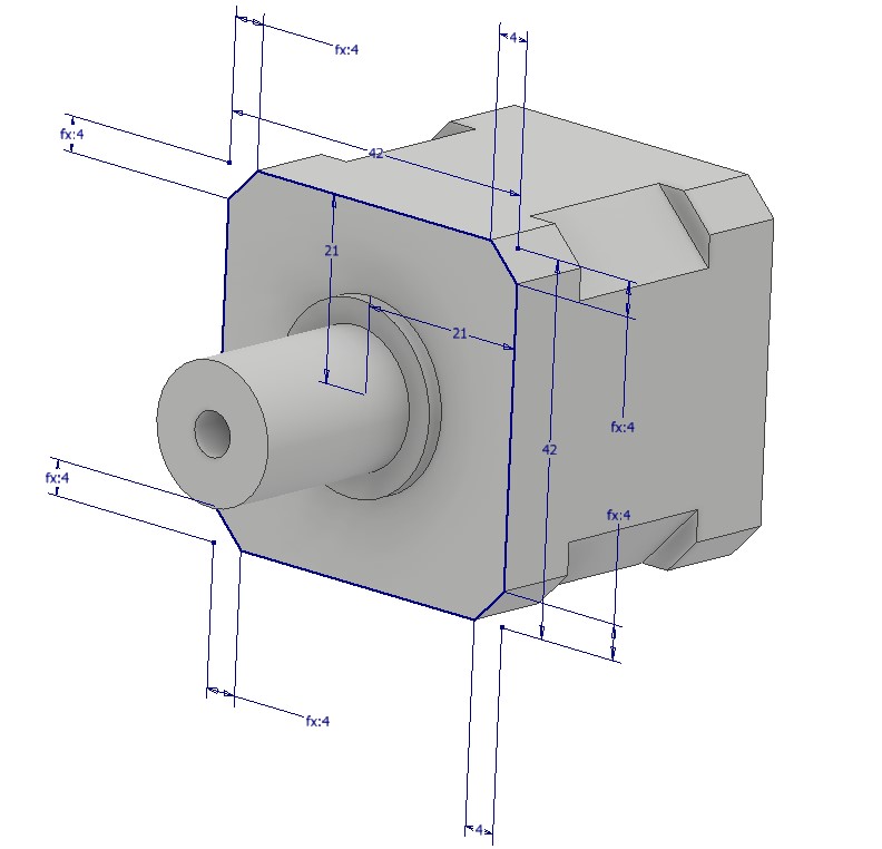
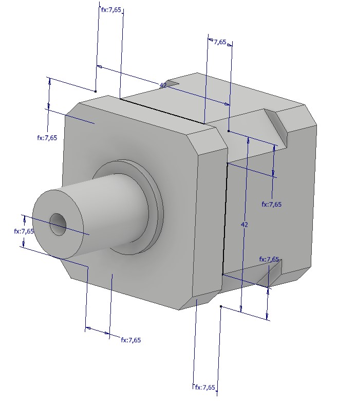
I used derive option in Autodesk Inventor 2018, to create a copy of a motor, which size was 30 % of the Nema 17 stepper motor. The motor itself was created with Autodesk Inventor as well. I started it by creating a sketch on a x-y plane and chamfered the corners based on the actual motor dimensions and extruded it.
Then I created the middle section in the same manner and the rear section as well.
Then in the front, I created the circles for the axel (diameter 5 mm, hole for casting) and the area surrounding it and extruded them as well.
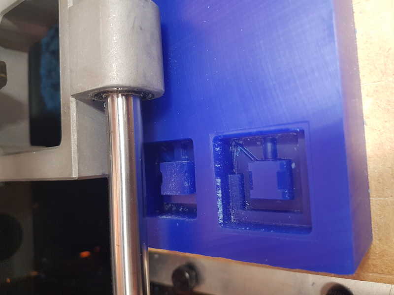
The motor modeling is very fast and most of the time is spent on the measurements. I made two versions of the box for the molding. The first one failed miserably, because I didn't create the slopes for the finishing milling bit (0.79 mm ball) and the mold depth was more than 5 mm (total length of the thin cutting part) and the milling machine pushed my molding wax (double-sided tape) so hard that it started to move on the sacrificial board.
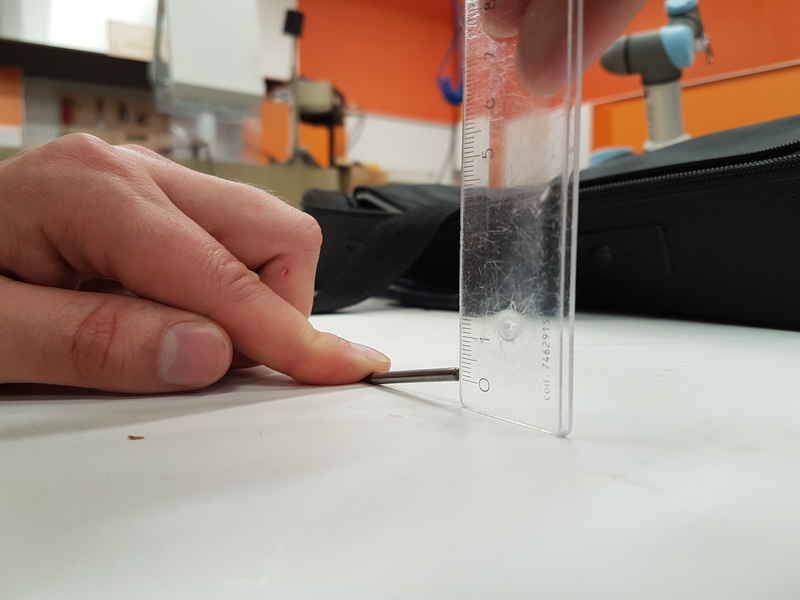
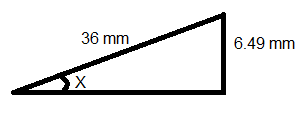
I pressed pause on the machine and canceled the job and moved back to drawing desk. Now I measured the angle that milling tool requires for it to be able to go all the way down. I put it against a surface and measured the distance it is from the surface when the side touches the surface, which was 6.49 mm. As the lenght of the milling tool was 36 mm (as it forms a right-angled triangle the angle between the measured sides is 90 degrees), I calculated that the wall angle has to be at least 10.386 degrees (in Libreoffice Calc =DEGREES(ASIN(6.49/36)).
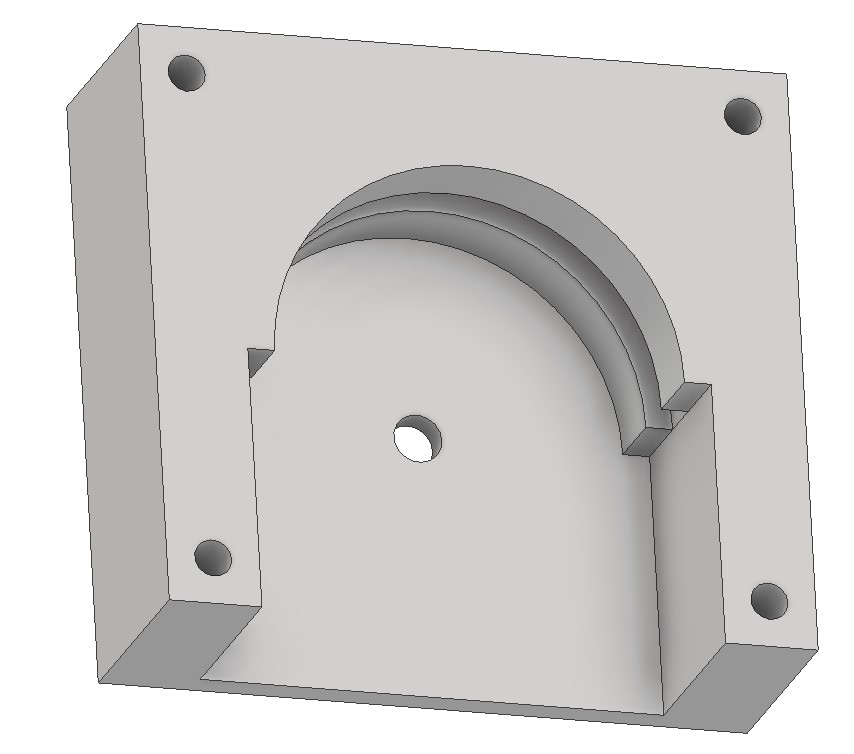
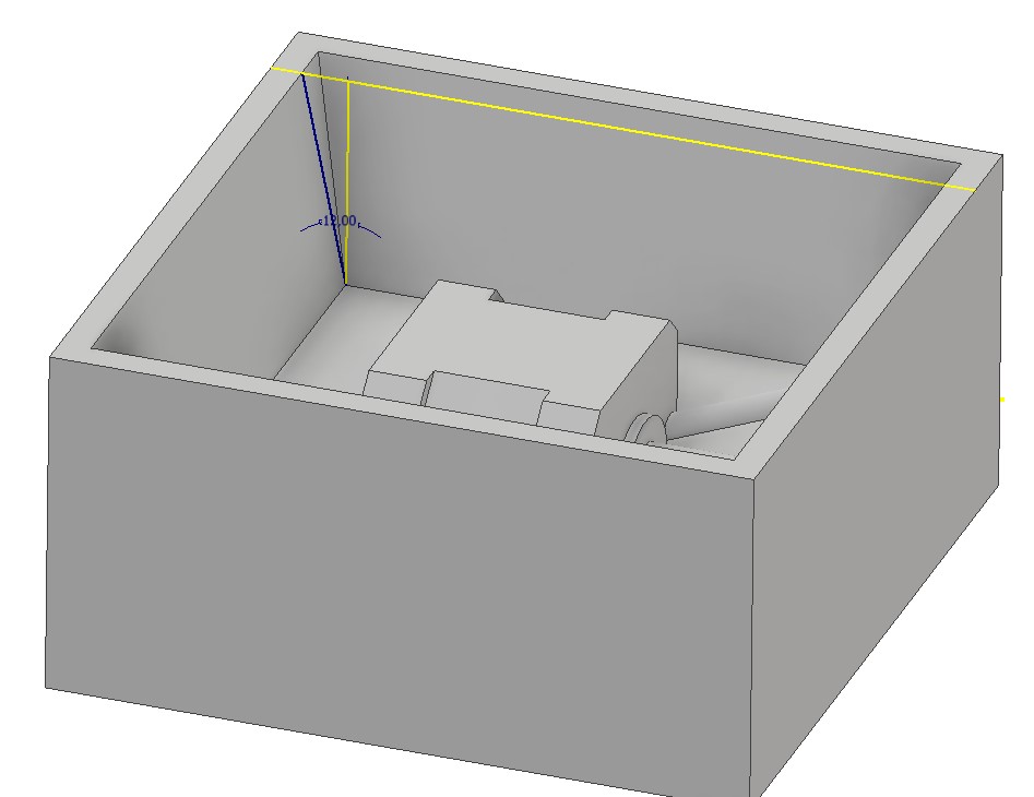
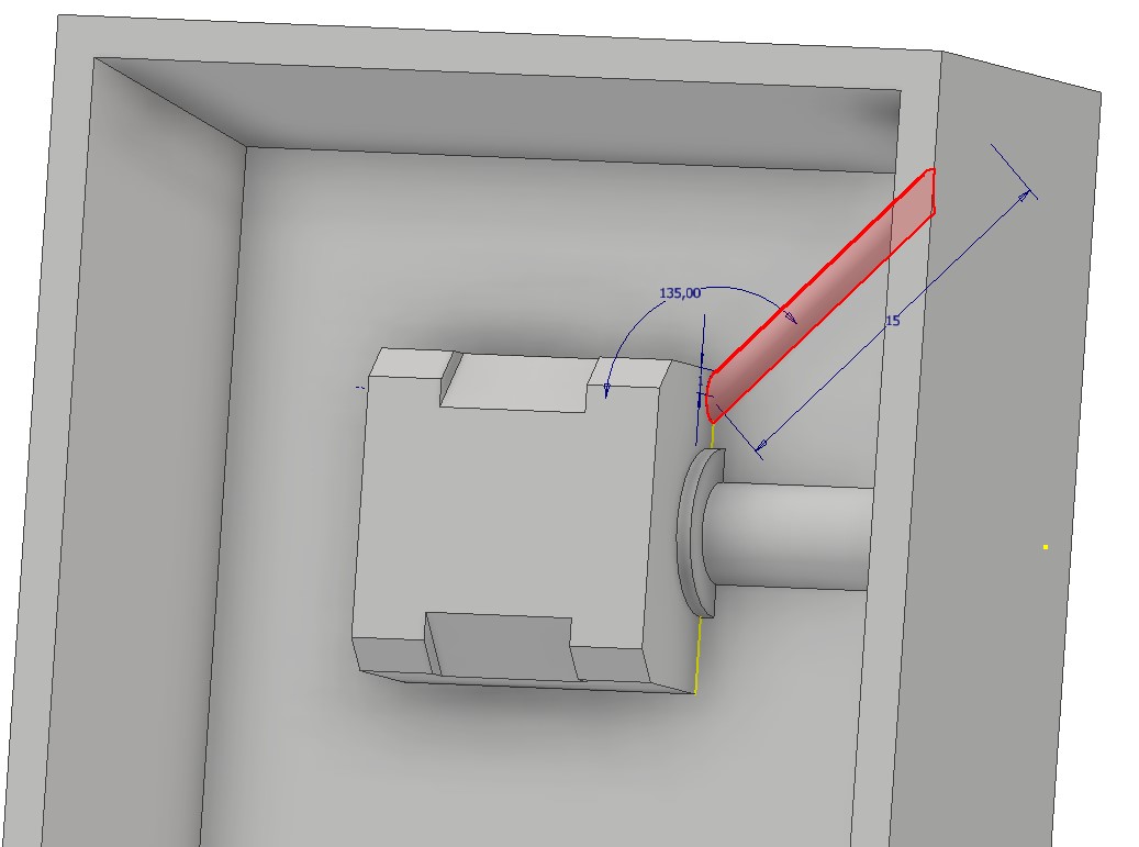
I used 12 degrees in my design, which was successful. To make this, I created a rectangle around the motor with 14 mm distance from all sides. I extruded it and created a shell with 4 mm thickness. Then I drew sketches on all walls with triangle, which had 12 degree angle between the bottom and the wall.
I extruded them all (cut) to remove the excess to make the walls in 12 degree angle. I created a hole (diameter 2 mm, 45 degree angle) for air removal, which was in the upper corner. I made a 2 mm circle and then swept it along the 45 degree angle path to outer wall.
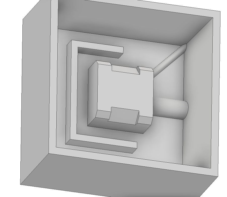
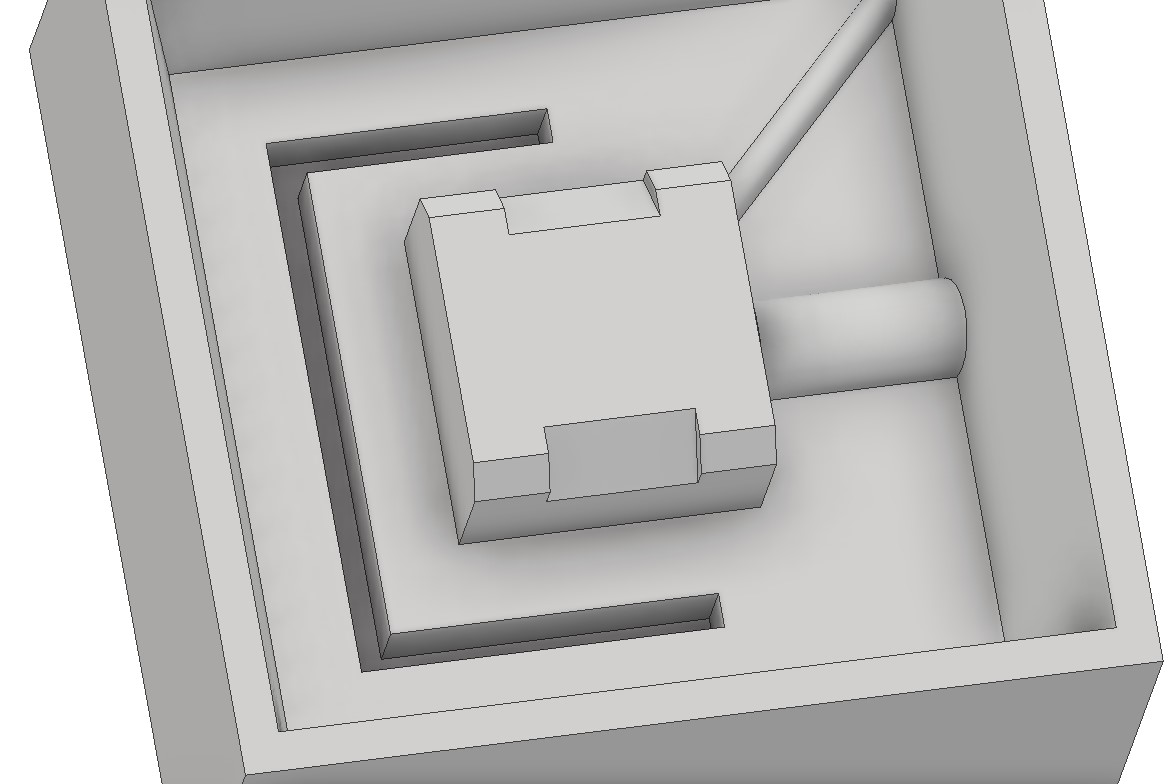
Lastly, I wanted to create continuous part to hold the mold sides together. I decided to make a shape from three extruded rectangles and its negative on the other side of the mold. Because I only changed the name of the file and saved it in a new file and reversed the direction of extrusion, the air hole and the extrusion were in the wrong side. I saved both sides of the mold as STL files for the milling and didn't see the mistake yet.
Milling of the mold
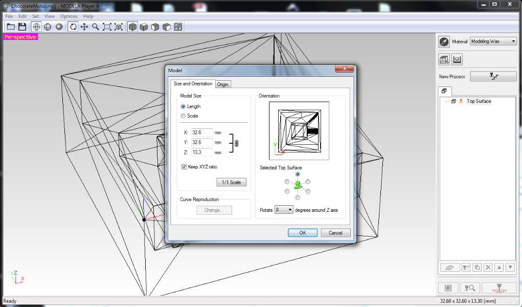
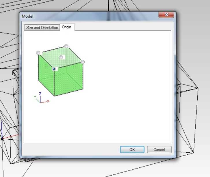
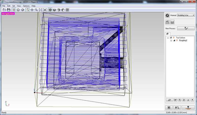
For the milling of blue machinable wax, we used our Roland SRM-20 CNC-milling machine. To create the file for the milling machine we used Roland Modela player 4. I opened the STL files and started to work on them. When the model is opened go to Set -> Model and check that your size and orientation are correct. Orientation can be changed by selecting differnt Top Surface and the model can be rotated as well. Switch to Origin page and set the lower left corner as the starting point.
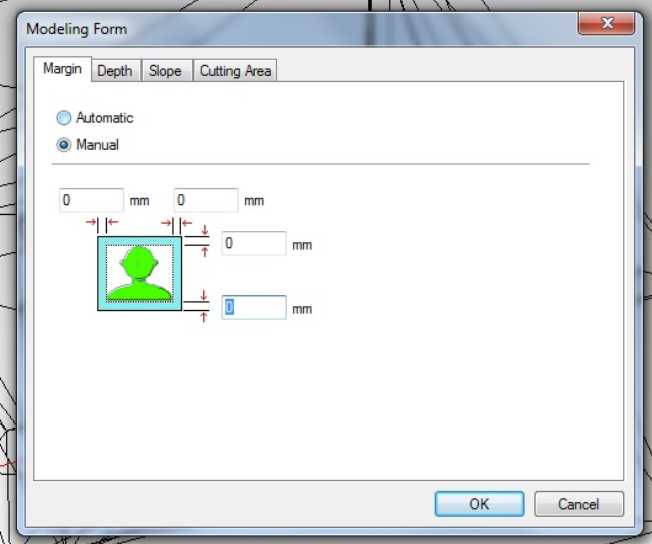
Then open Set -> Modeling Form and set all the margins to 0 mm. Other panels don't need to be changed, because the whole mold is designed with margins and slope. From depth, you can check the maximum depth of your milling process, which is useful value for the tool selection and position.
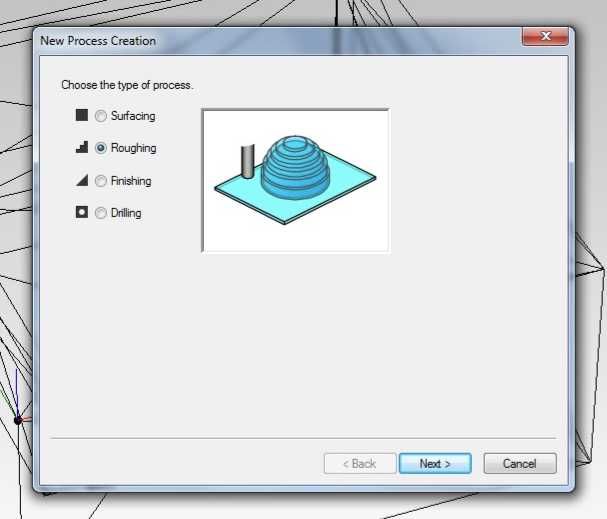
After that open Set -> New Process Creation, where you can select the process. The first one I used is the roughing.
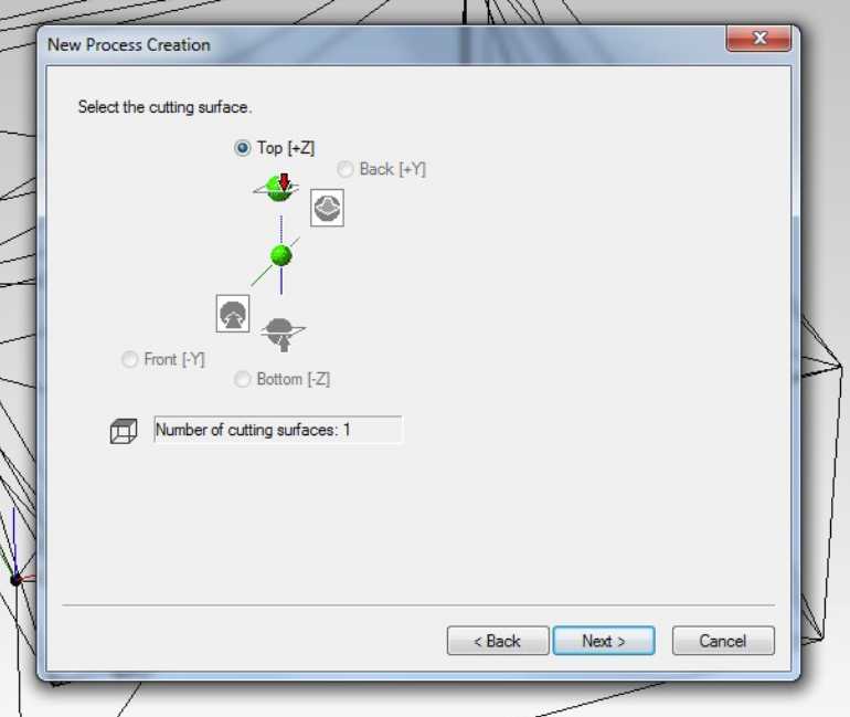
Click next, which opens the Select cutting surface, which is Top [+Z].
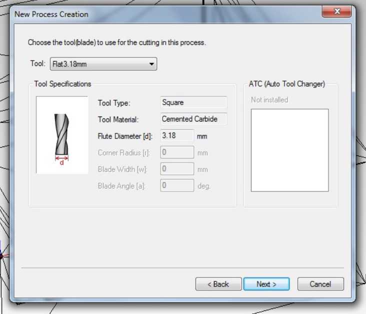
Click next, which opens the Choose the tool to use for the cutting in this process. In there, I selected Flat3.18mm tool (It was already defined by the Fab Lab staff and didn't require any changes) for the roughing.
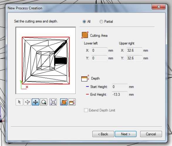
Click next, which opens Set the cutting area and depth. It was correct for my case.
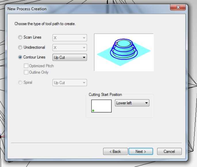
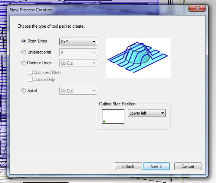
Click next, which opens the Choose the type of tool path to create. In this everything was correct as well.
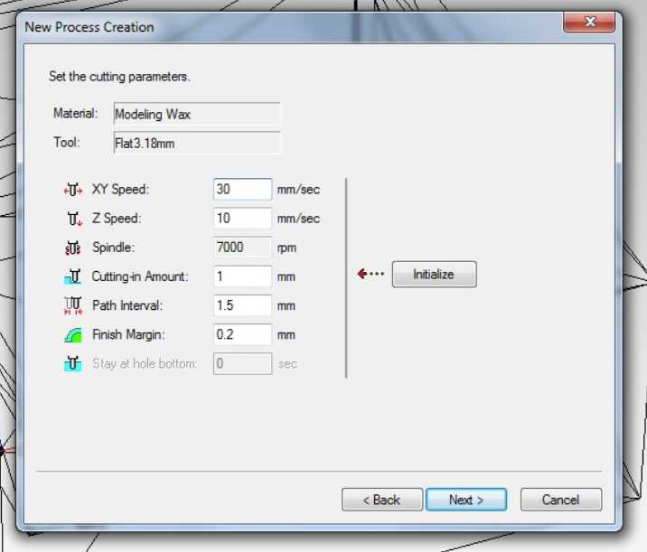
Click next to open Set the cutting parameters. In there, based on Ivan's settings, I changed the XY Speed to 30 mm/s (how fast milling tool will move horizontally in the material), Cutting-in Amount to 1 mm (Depth of the cut) and Path Interval to 1.5 mm (offset between parallel cuts).
After clicking the next, you can press create the toolpaths and program calculates the tool paths based on the settings you just set up.
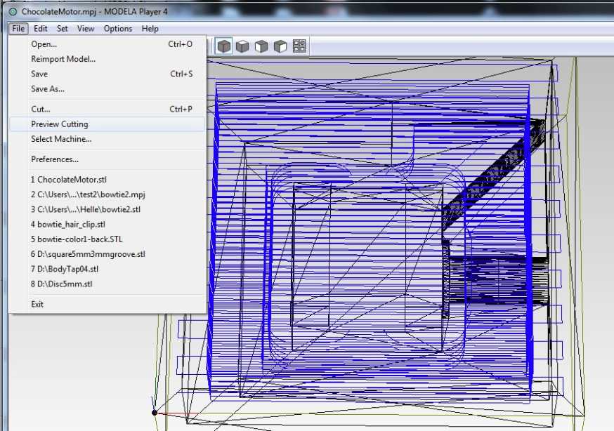
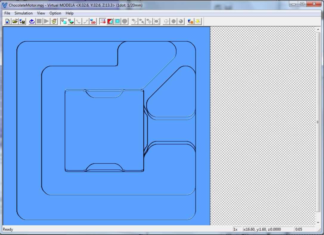
Now the roughing setup is done and it can be simulated in Virtual Modela. It is opened from File -> Preview Cutting.
Press play button to simulate model and it can be viewed in 3D by selecting 3D button. Estimated cut time can be checked by pressing clock button. In my roughing the milling time was 5 minutes.
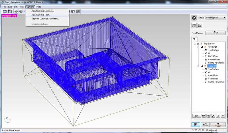
I closed the Virtual Modela and once again selected the Set -> New Process Creation, where I chose Finishing this time. For the finishing, I wanted to use Ball0.79mm tool, which did not exist in the tools. I needed to use Ball0.79mm tool, because we didn't have flat tool in our Fab Lab and I needed fine details for my mold, which couldn't be done with 3.18 mm tool. Only the Flat0.79mm tool was in the existing tools. So I went to Options -> Add/Remove tool and copied the Flat0.79mm tool and switched it to ball nose tool.
I also changed the Cutting Amount to 0.1 mm based on the Eino's work last year. I started over the New Process Creation. This time I selected the Ball0.79mm tool. For the tool path, I selected the Scan Lines X+Y, because it makes finishing milling in both X and Y directions and the finish is a little bit smoother. The difference can be seen clearly in the simulation.
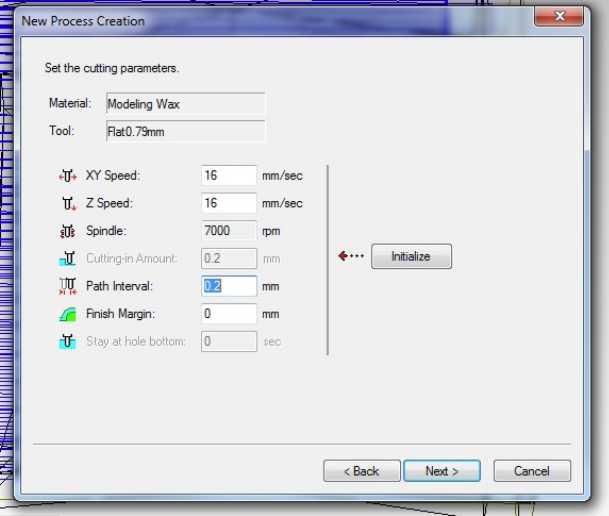
The cutting parameters in finishing can remain in the original settings. XY speed 16 mm/s, Z speed 16 mm/s, Spindle 7000 rpm, Path interval 0.2 mm and Finish margin 0 mm.
I simulated this as well and saw that everything went smoothly. Estimated time for the finishing was 25 minutes.
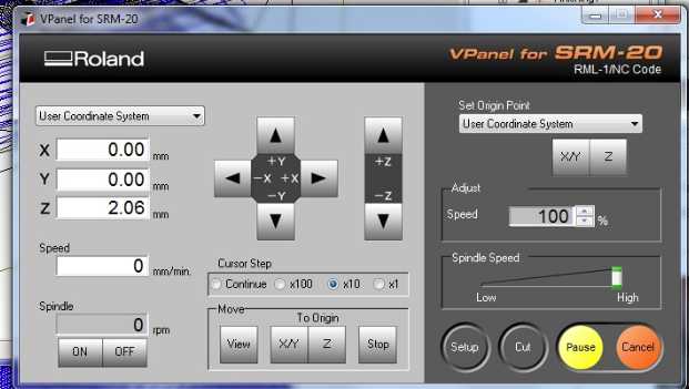
Then I changed the flat 3.18 mm tool into milling machine and set origin points for the X/Y-axis and Z-axis in the Roland VPanel for SRM-20.
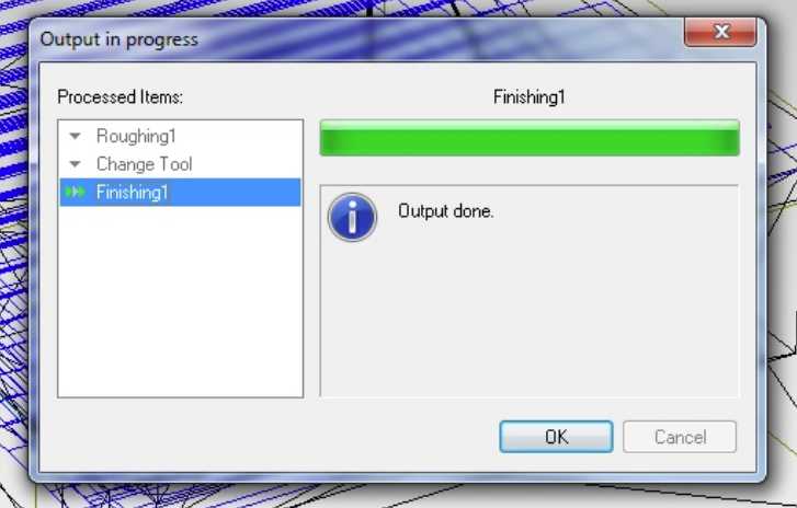
As it is previously explained in Electronics Production, I won't go into details. Then, I selected File -> Cut, which opens the cut menu. Select Output and when everything is ready press continue.
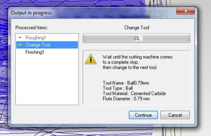
After the roughing is done the machine stops and you can change the tool and you have to press continue to continue to finishing.
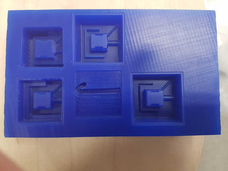
The chippings and dust from the milling was collected in a platic box to wait for the melting and casting of new modeling wax. In the next image can be seen the steps towards the final mold. One problem I faced, was that the tool was too low in the machine and it couldn't make the full movement and the tool plunged into material and stopped automatically when the tool was stuck. Luckily, I was standing next to milling machine and stopped everything, removed the tool, made simulation drive in the air to check that everything is fine, put the material back, zeroed the z-axis and put the milling tool all the way up in a way that it could make all the necessary movements and would still be able to mill the molding wax. Finally, I finished the mold making. It was a learning experience and a little bit stressful at that.
Casting the mold
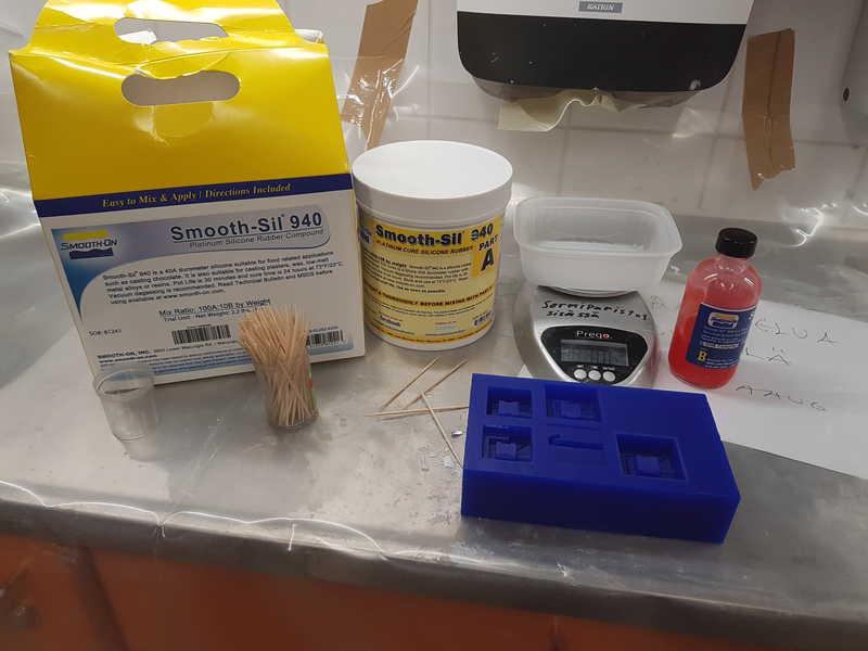
I used Smooth-Sil 940 to make the actual mold for my chocolate motor.
The pot life of the Smooth-Sil 940 is 30 min and cure time 24 h, so I had no hurry to cast it in the mold. The silicone part A was very viscous and required part B to make it more like fluid and less like rubber. I measured them according to instructions 10 parts of part A and 1 part of part B. Total amount was 36 g of silicone.
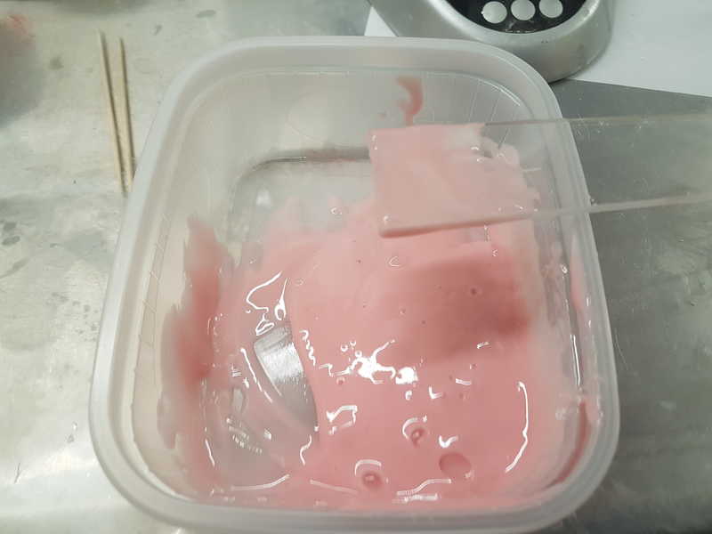
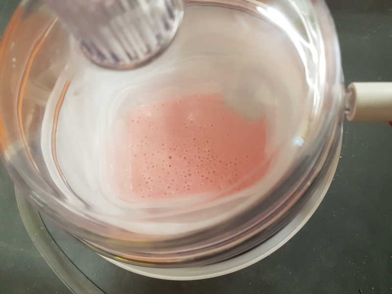
I mixed the mixture for about 3 minutes and then put it in vacuum for another 3 minutes. You could see a lot of air bubbles in the silicone and slowly the bubbles were bursting.
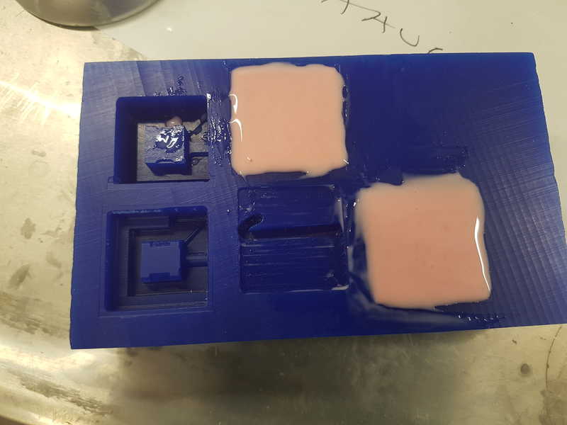
When I was happy with the amount of bubbles, I opened the valve in the vacuum chamber to make it possible to open it. Then I slowly poured the silicone in the mold and slowly guided a cocktail stick through the hard parts to make sure that all the surfaces were wetted with silicone. It seemed to slowly settle in.
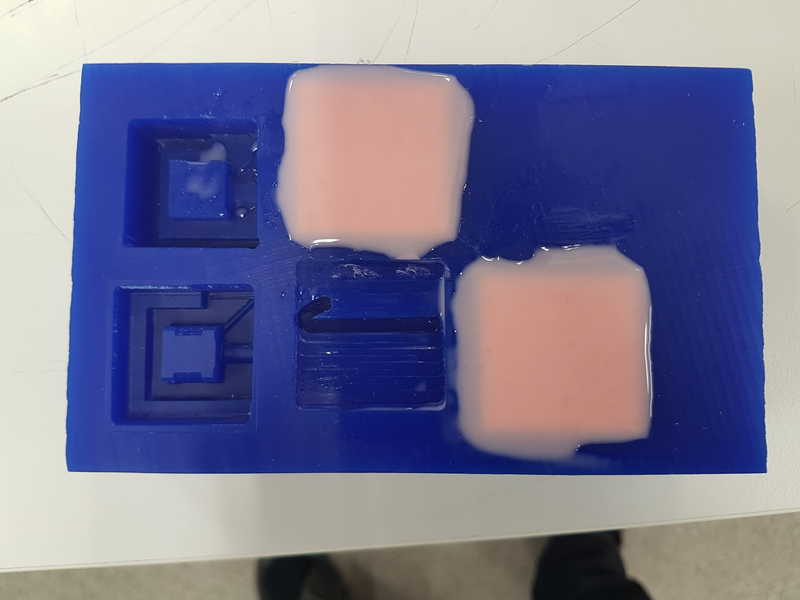
With this silicone it takes 24 hours to cure.
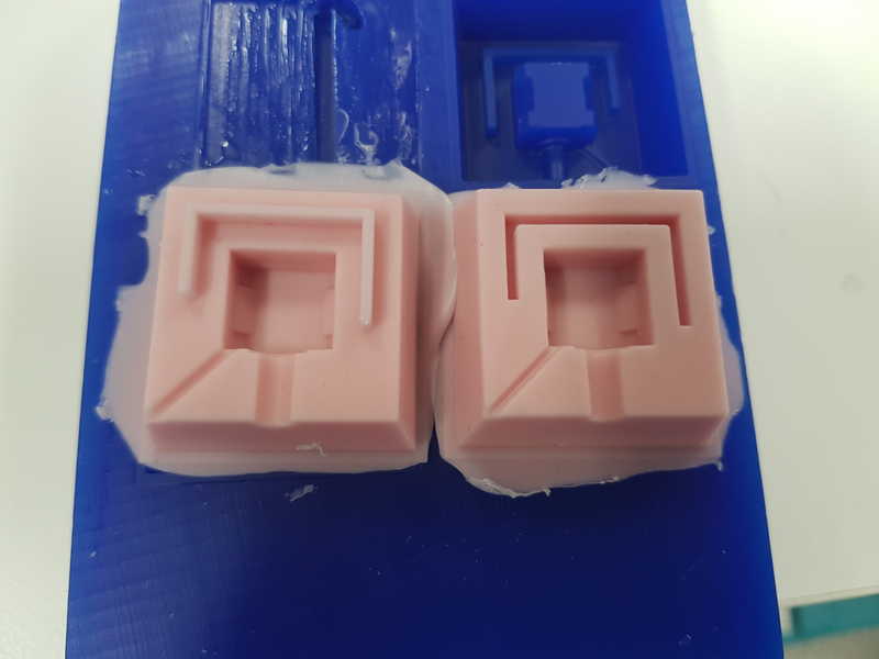
I carefully removed it from the mold and it looked fine, but I realized that I had not mirrored the mold, but only made the extrusion in different direction, so I had to cut small piece of the mold for it to fit together. The air vents are in the opposite sides from each other, but now I have 2 1 mm vents.
Casting the chocolate
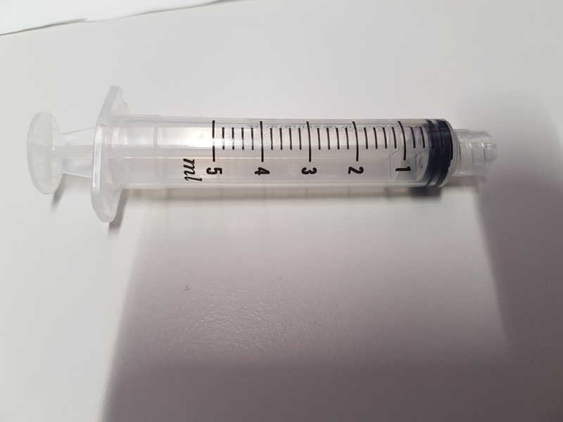
I tested the mold with water, because I was a little concerned about the air vents, but the water came out through the vents and it was water tight mold, so I was happy to start the chocolate casting. I bought cooking chocolate for the casting of my miniature stepper motors. I cleaned the silicone with soap in warm water, rinsed it and dried it. I put the sides together and used 5 mm syringe to fill the mold through the motor shaft hole.
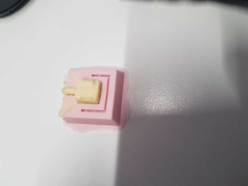
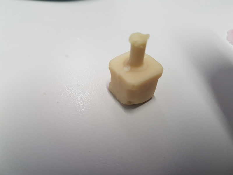
Even with the issue with mirroring the casting went well and chocolate filled almost the whole mold. If I had heated the chocolate in higher temperature (it was barely runny), probably the result would have been even better.
Reflection on this weeks assignment
I really enjoyed this weeks assignment, but I seemed to make all the possible mistakes. Maybe I wanted to finish everything very quickly to be able to move ahead with the peristaltic pump for my final project. Most of the mistakes I made were related to not thinking things through and I'm a bit frustrated with myself. Anyway it was really fun and I learned a lot and told to other students my errors, so they don't have to repeat them.
The files used in the assignment are shared below: ChocolateSlopeA.zip All the files (ipt, stl, roughing, finishing) needed for the chocolate motor A side molding
ChocolateSlopeB.zip All the files (ipt, stl, roughing, finishing) needed for the chocolate motor B side molding