Assignment 11: Input devices

Assignment:
Group assignment:
- Measure the analog levels and digital signals in an input device
Individual assignment:
- Measure something: add a sensor to a microcontroller board that you have designed and read it

Group assignment
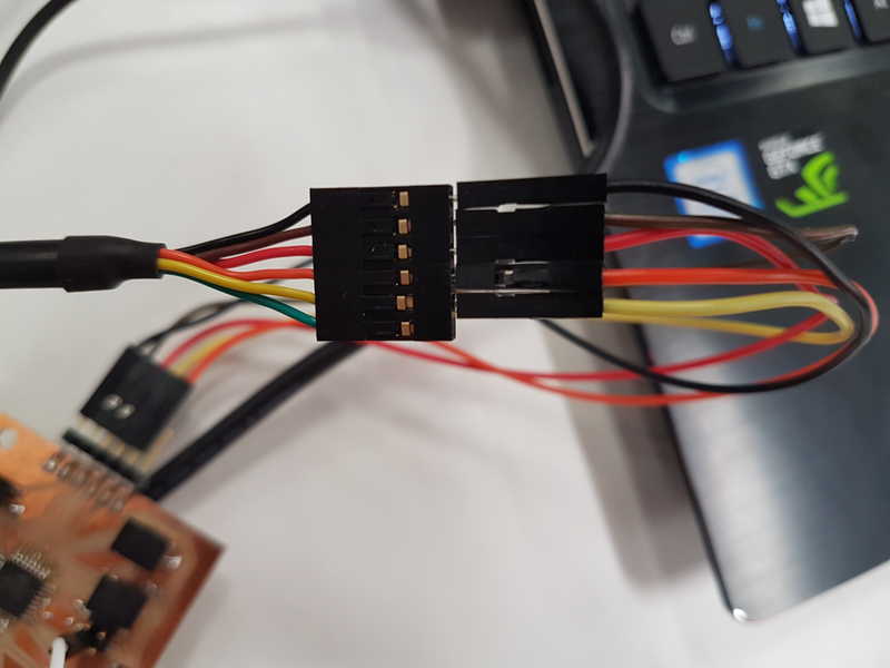
We worked with Jari's light sensor to measure the analog levels and digital signals. We used oscilloscope to measure analog level from the sensor and digital signals from the FTDI cable. More about the group work is in the Input devices group page.

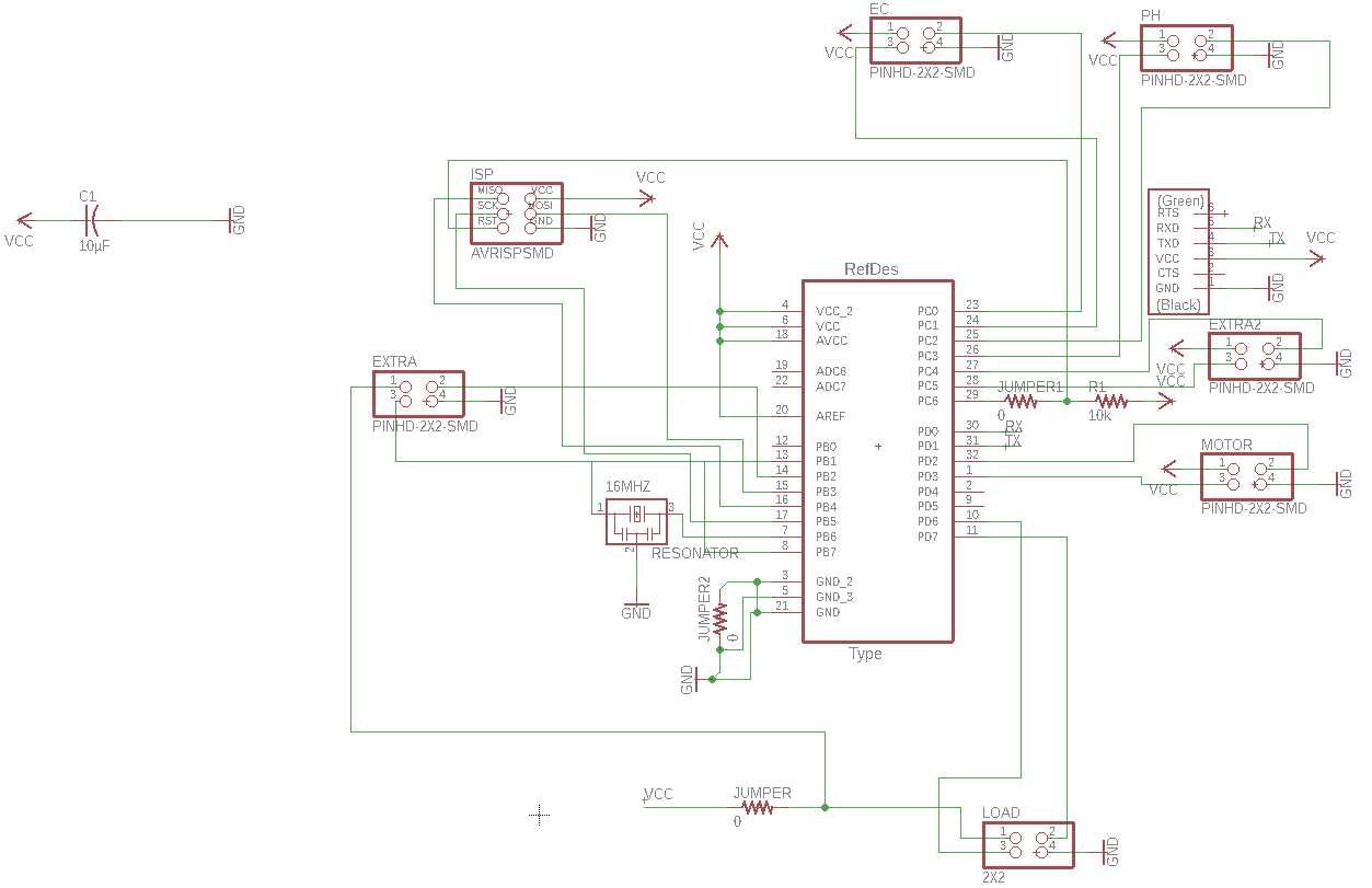
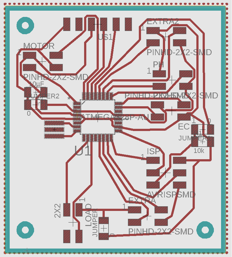
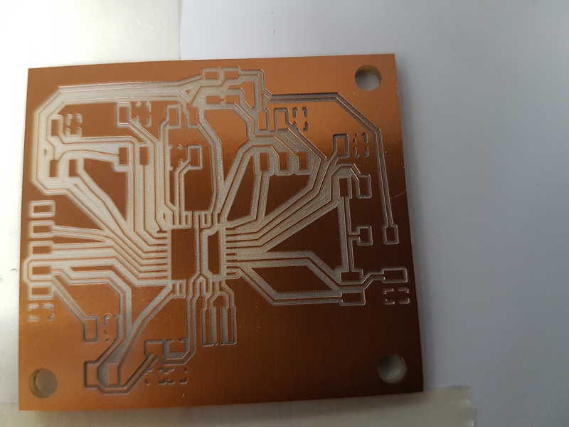
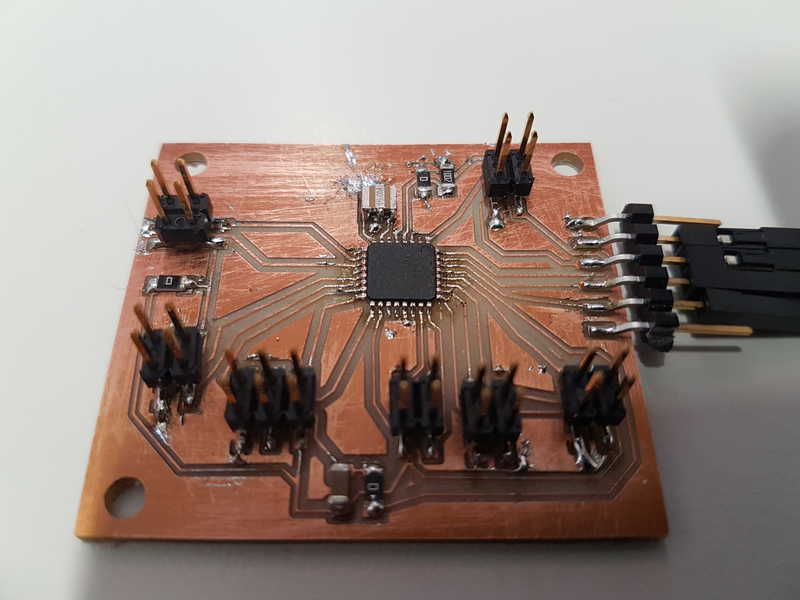
Designing board for my final project
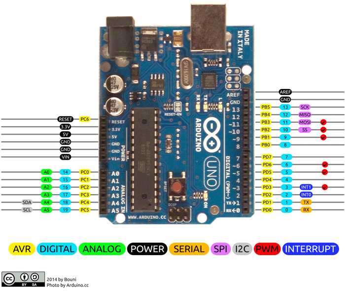
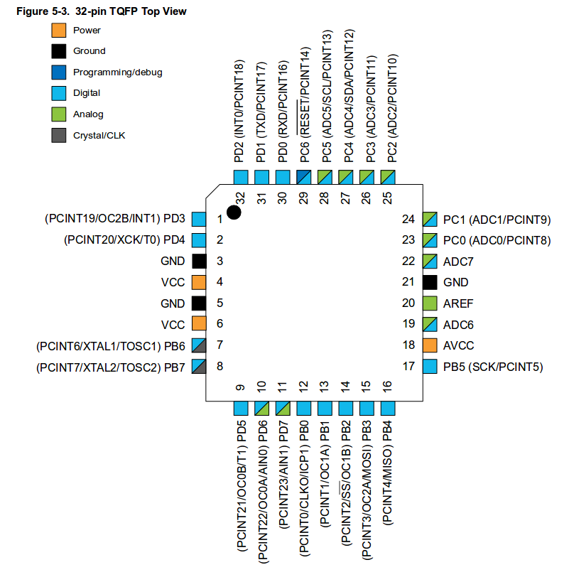
I started to create board similar to Arduino Uno (microcontroller ATmega328p), because I need a lot of pins for my final project.

PinConfigurations
There are four more pins in the ATmega328p than in the Arduino Uno.

PinConfigurations
Pinout for ATmega328P (Atmel Corporation, 2018)
I'd like to call it Ariduino. This week made it possible to start working on it and to connect one of my sensor types to that board. I was going to aim for pH meter for my final project, but I didn't get the pH sensor in time. So I decided to study all of the example Fabduino boards and based on those and our instructor Juha-Pekka Mäkelä’s board, I started to create my own board. It was really interesting, but time intensive work. At first, I decided to make connections ready for all of my sensors, motors and LCD screen, based on the pin configurations. Therefore, I needed to create multiple connections, which proved to be a challenge in the single layer PCB design. For all of the sensors and motor, I made a connector with VCC, GND and an input and output pins. Pins for the pH, EC and load need to have analog possibility for signal and motor and LCD can use digital connections. I also made a FTDI connection for power and ISP connection for the PCB programming. I needed to create 3 jumpers to get everything connected. It is really hard to make a single sided board with this many connections. I created holes for the screws for the assembly as well.

PinConfigurations

PinConfigurations
I used the Roland SRM-20 to mill the board. I had to remake the board a couple of times, because our sacrificial layer was crooked and depending on the Z zero placement, the difference in the final board was huge. The lines in the upper parts were really thin and I didn't want to risk poor connections and remade it.

PinConfigurations
All the components for this board were accessible from our Fablab.

PinConfigurations

PinConfigurations
I tested the board for short circuits and connections. All seemed to be fine, but one of the legs in the ATmega328p was not connected properly and after some head scratching with the board programming, I added more solder in the legs and it worked immeadiately without any problems. The problem is that, when you measure the legs you are going to push it down and it might seem to be connected. The board should be placed under microscope and add more solder or fix the poor connections and not to just see if it works.

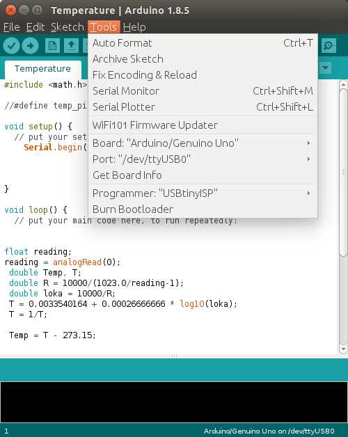
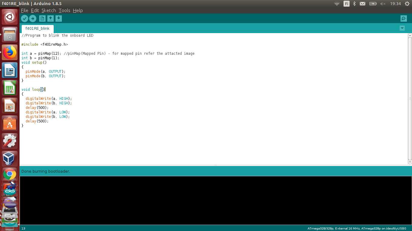
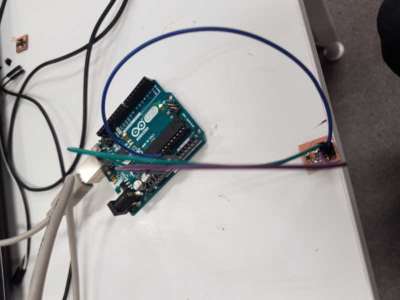
Burning the bootloader
I programmed the PCB with Arduino IDE. It has all the necessary tools for the programming in it for ATmega328p microcontrollers, which makes the programming straight forward process. I used my own FabISP to make the programming.
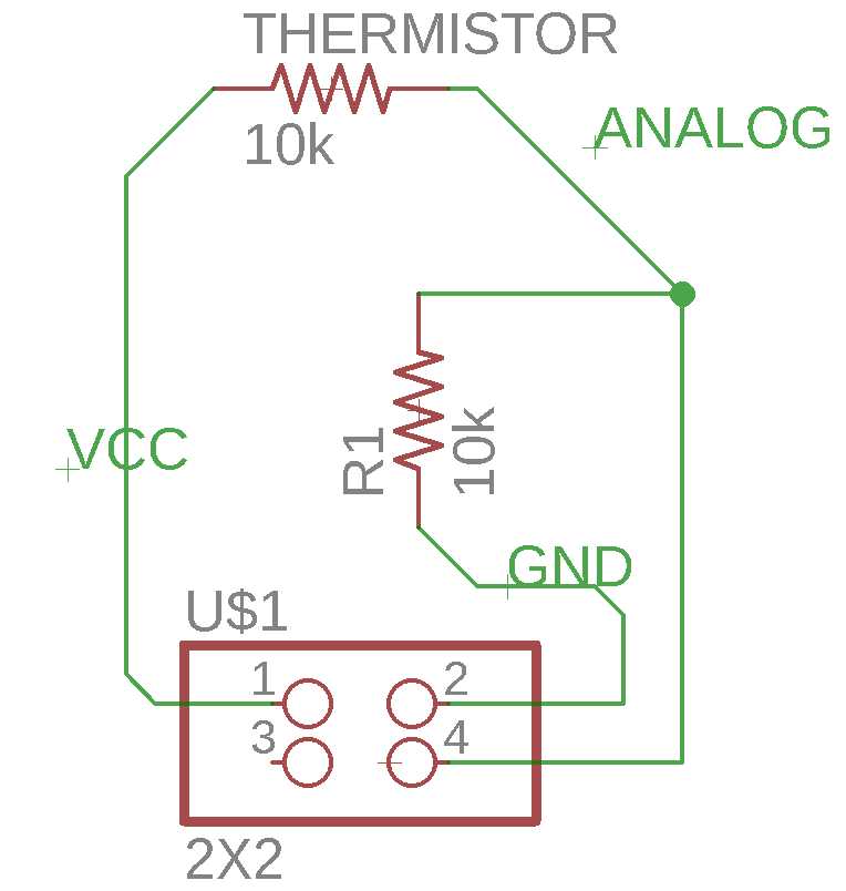
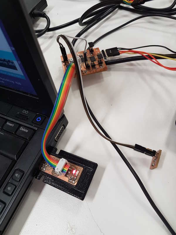
PinConfigurations

PinConfigurations

Temperature sensor
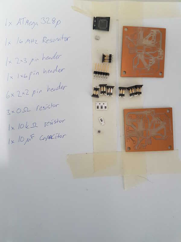
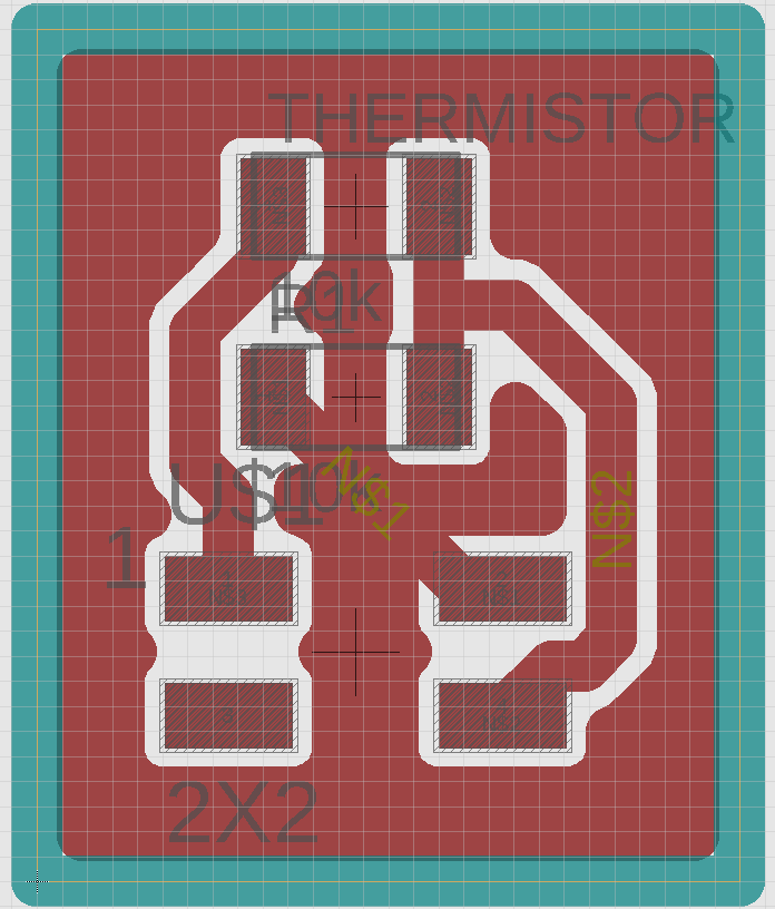
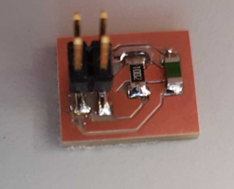
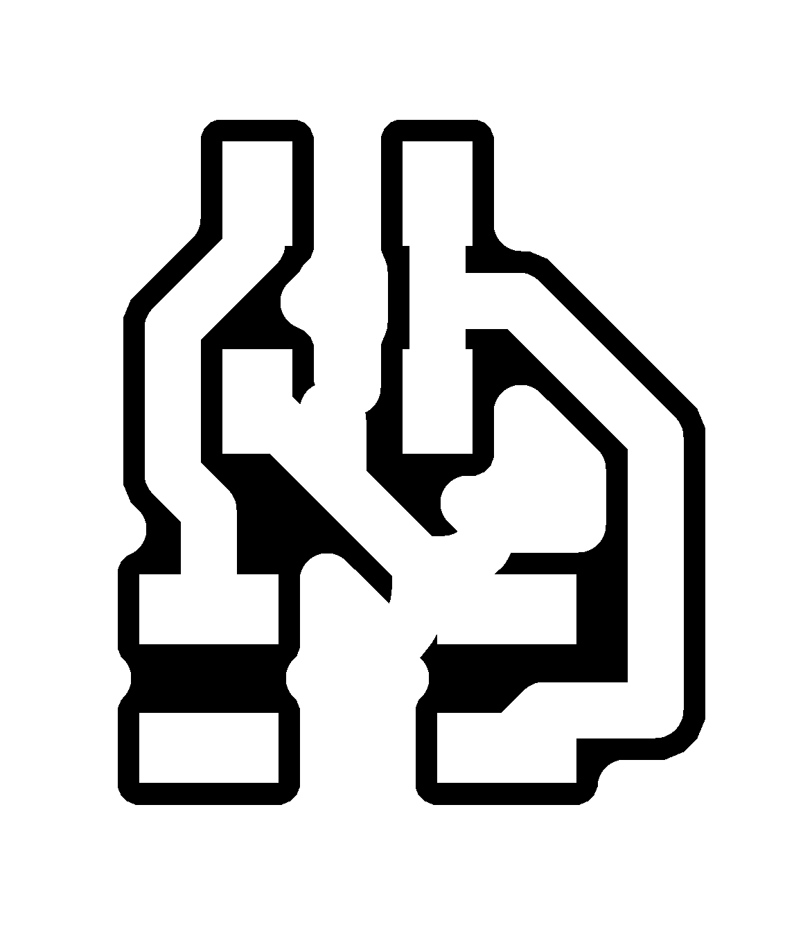
I used NTC thermistor to measure temperature. It is quite simple system and to make it work with ATmega328p, the sensor cannot be connected to Wheatstone bridge, because there are no differential analog pins in the ATmega328p. I used a single 10k resistor and 10k thermistor with 2x2 pin header to make the temperature sensor.

PinConfigurations

PinConfigurations

PinConfigurations

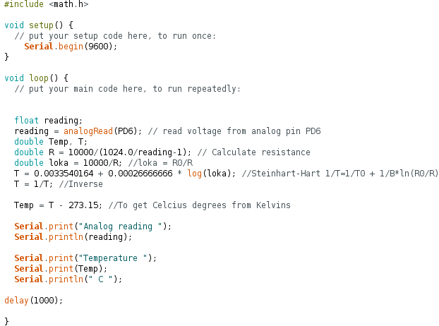
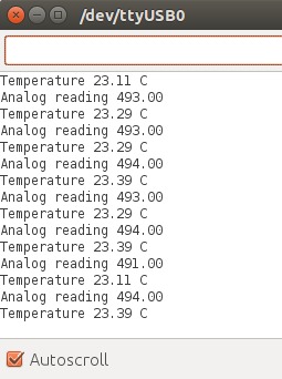
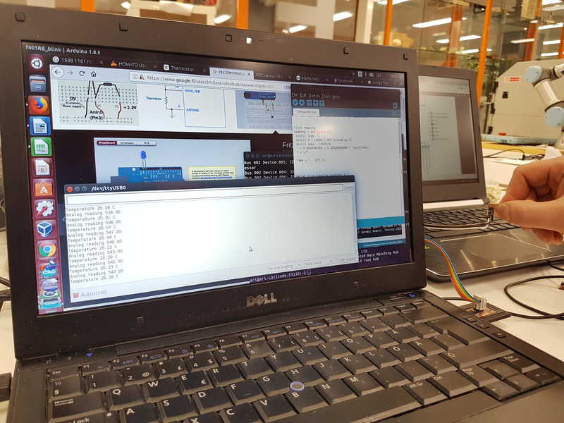
Measuring the temperature
I had made a temperature meter for Arduino in the past and I reused the code for this task, but changed the pin for a different position PD6. The code itself is very simple. It solves the first two termes of the Steinhart-Hart equation (third is so much smaller that it can be dismissed) and changes it to temperature in Celcius degrees. ATmega 328P has 10-bit analog to digital converter, therefore the input voltages between 0 and 5 V are changed to integer values between 0 and 1023. The resolution is 5 V / 1024. The temperature is then printed to serial monitor.

Code
At first, I had a problem with getting serial port working, but then I got a comment that I have probably connected FTDI Rx to Rx and Tx to Tx and the should be Rx to Tx and Tx to Rx. After I changed used cables to correct that issue, the serial port was working fine.

PinConfigurations
It took me a long time to understand why the code wasn't working. Then I tried the sensor and code with an Arduino Uno and everything worked perfectly.

PinConfigurations
Then I realized that I am using basically Arduino Uno and the analog pins in my board won't work unless they are analog pins in Arduino Uno. After that realization, I changed the signal pin from PD6 to PC0 and the sensor worked without any problems. The FabISP holder you can see in the picture is borrowed from fellow student Kati, who 3D printed it.

PinConfigurations

PinConfigurations

PinConfigurations
An obvious problem, but it took me a lot longer to realize it than I care to admit.

Reflection on this weeks assignment
I really enjoyed this weeks assignment. There was plenty of learning and I understand a lot more about electronics design and signals. I had done some temperature measurements earlier with Arduino Uno, but that background didn't help me much with the assignment. Now I understand that my Ariduino board is not as useful as I hoped it would be, because I can only use few analog signals from the microcontroller. Basically I have to make sensors with Attinys on them to read signals and collect them in Ariduino as digital signals and use it to control other boards.

The files used in the assignment are shared below:
Ariduino board
Ariduino schematics
Ariduino traces
Ariduino traces milling rml file
Ariduino_outline
Ariduino outline milling rml file
Temperature sensor board
Temperature sensor schematics
Temperature sensor traces
Temperature sensor traces milling rml file
Temperature sensor outline
Temperature sensor outline milling rml file
Temperature sensor programming file
References
Atmel Corporation (2018) ATmega328/P datasheet, Retrieved from http://ww1.microchip.com/downloads/en/DeviceDoc/Atmel-42735-8-bit-AVR-Microcontroller-ATmega328-328P_Datasheet.pdf , cited 23 May, 2018.