Assignment 12: Output devices
Assignment:
Group assignment:
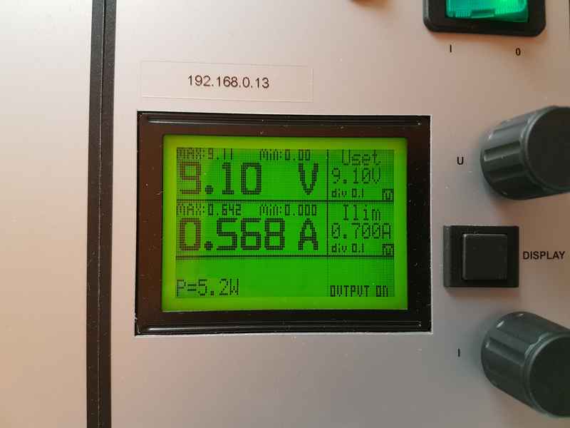
- Measure the power consumption of an output device
Individual assignment:
- Add an output device to a microcontroller board you've designed, and program it to do something
Group assignment
We worked with Kati's led pixels to measure the power consumption of an output device. We used a power supply to measure the power consumption. More about the group work is in the Output devices group page.
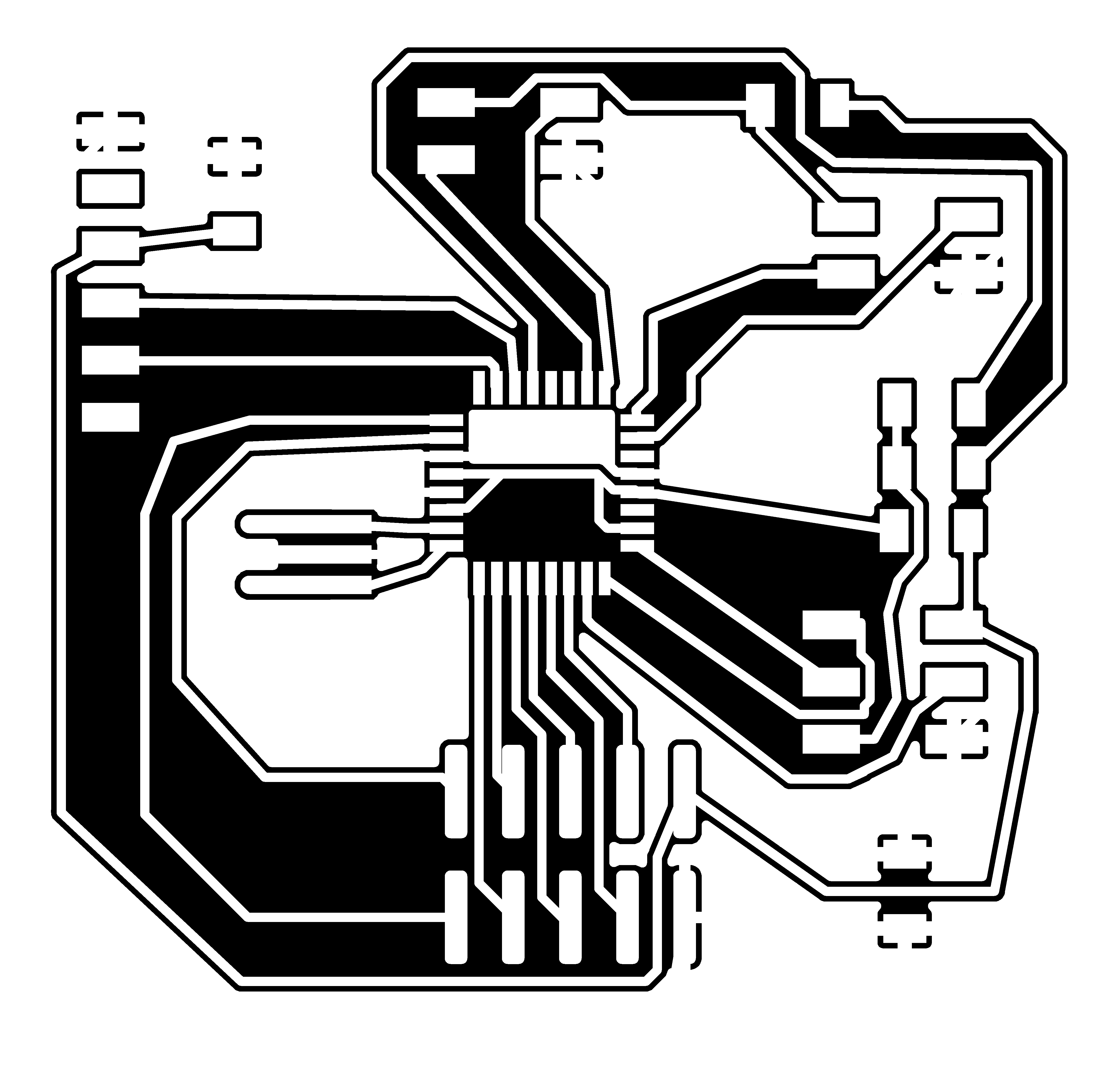
Designing controller board for motor controller board for my final project
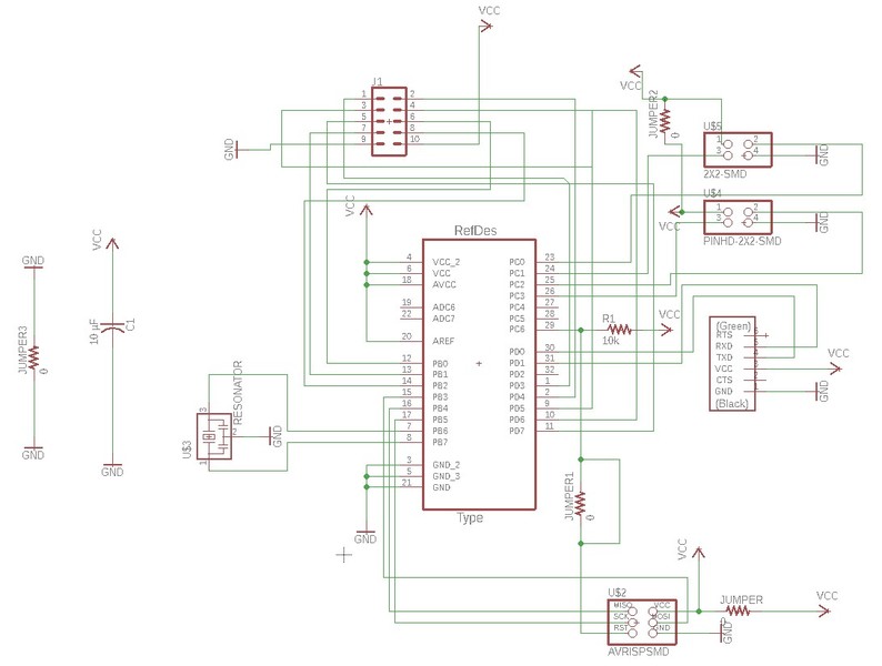
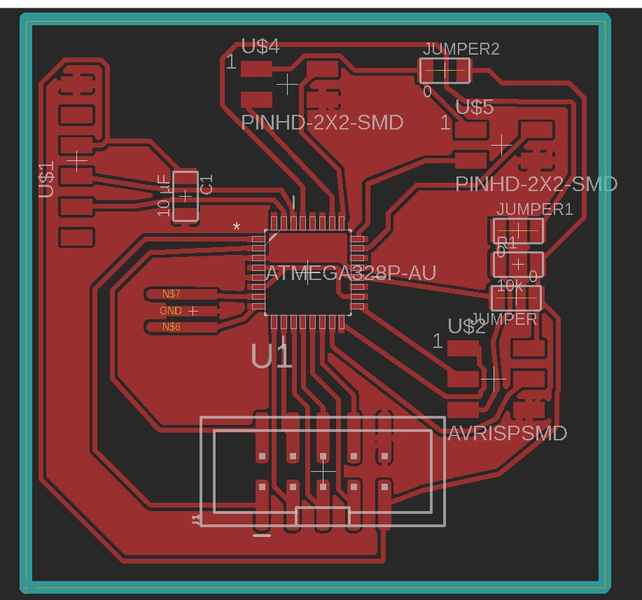
I need 4 stepper motors for my final project to run peristaltic pumps, so I started to make a control board for them based on the ATmega328P microcontroller. In the Input devices week, I created similar board and explaned the process in detail there. I decided to make a 10 pin connector, which has VCC, GND and two pins for the direction and step for each of the motors. This should be enough for my needs, because I won’t be needing the microsteps, because the full step accuracy (1.8 degrees) is enough for peristaltic pump control.
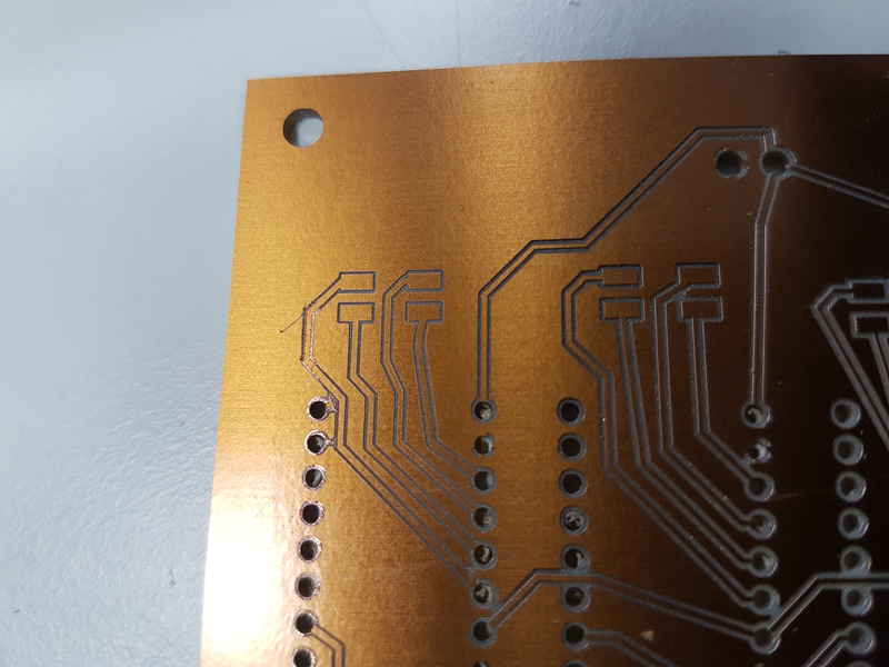
Milling the board
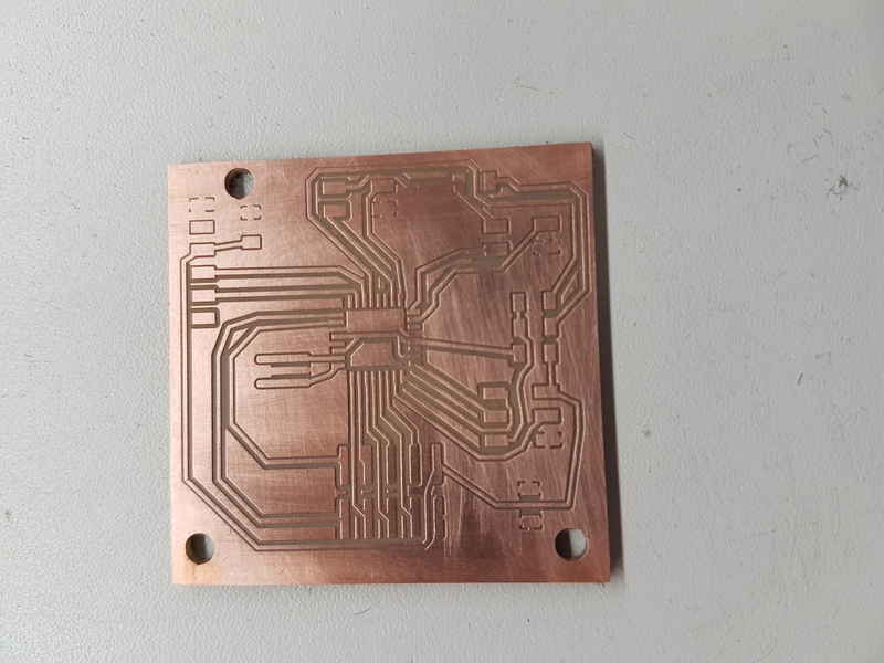
I used the Roland SRM-20 to mill the board. For the first try the cut wasn’t clean and I increased the depth of the cut and changed the tool. Because we have the V-shaped milling tools the cut depth plays important role in the milling process and seems to vary from cut to cut. Basically you can see whether the tool goes through the copper after a few seconds and you can restart with deeper settings if it doesn’t. The cut cannot be too deep or the cut will be too wide. At first, I used 0.08 µm cut depth, then 0.1 µm and finally the cut was made with 0.11 µm. Last week, I made the cut with 0.08 µm and it was really good, so you have to patiently increase the cut depth until you can see the copper layer penetrated. The quality of the cut was the best so far for my and all the lines were really cleanly cut.
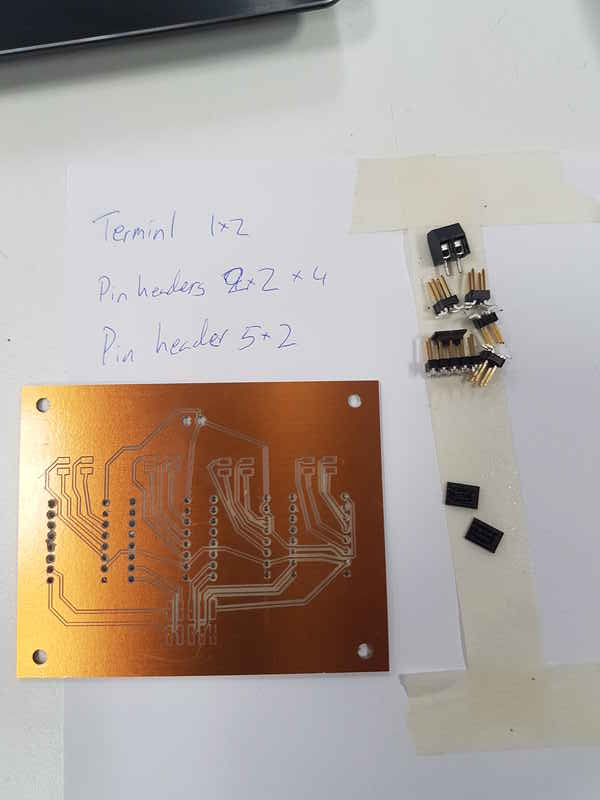
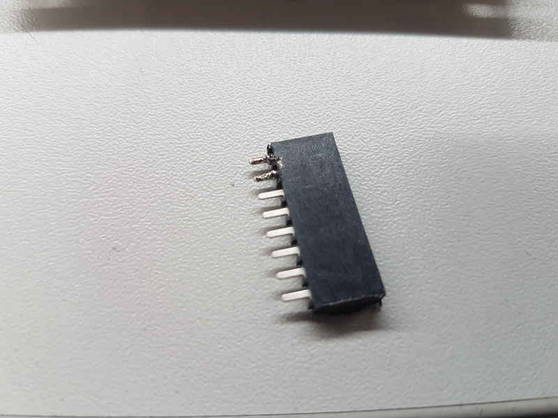
Soldering the components
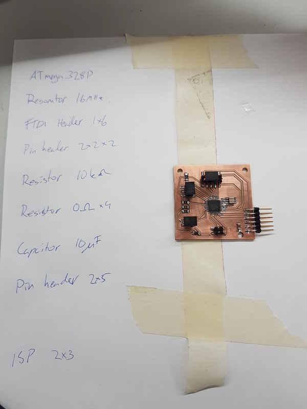
I collected the components for the soldering. Basically the requirements for the components are quite few in this type of board, because the motor controllers handle the motors. To conclude my experiment on the resonator pads, I must say that it was much easier to solder with longer pads.
Burning the bootloader
I used the Arduino IDE to program the ATmega328P and it was straight forward process. I used the Arduino/Genuino Uno setup and that’s it.
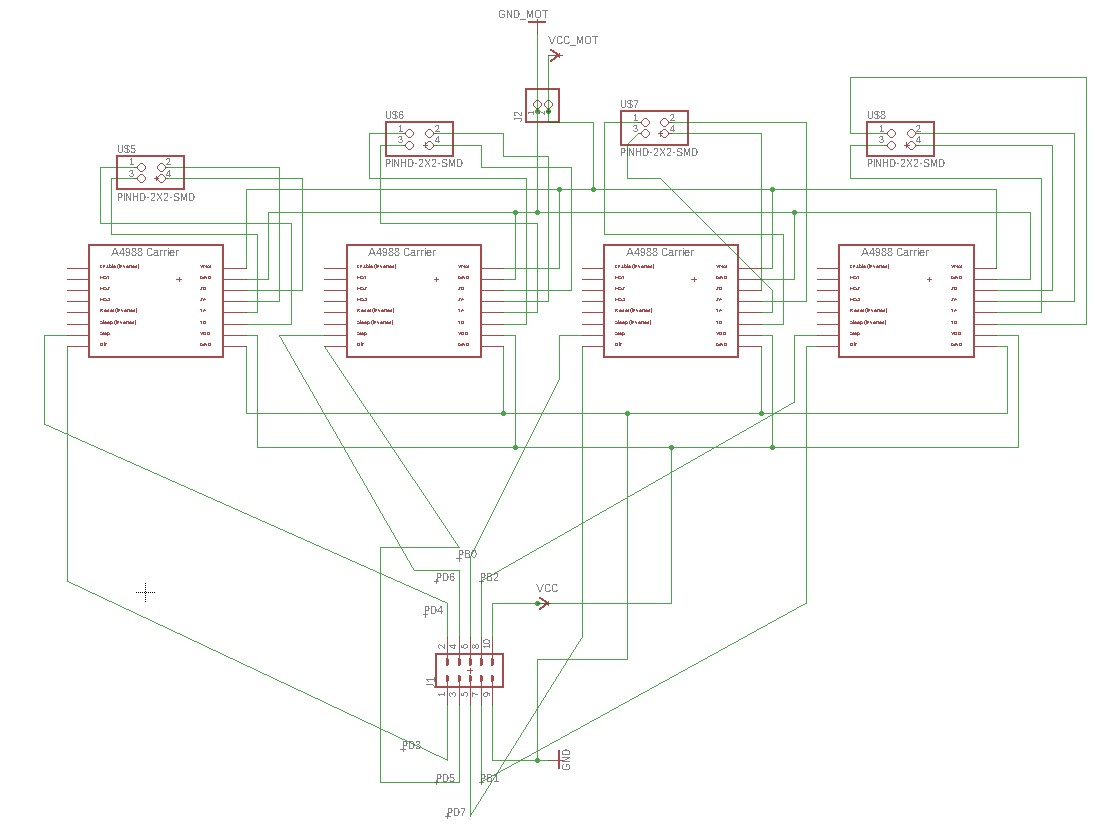
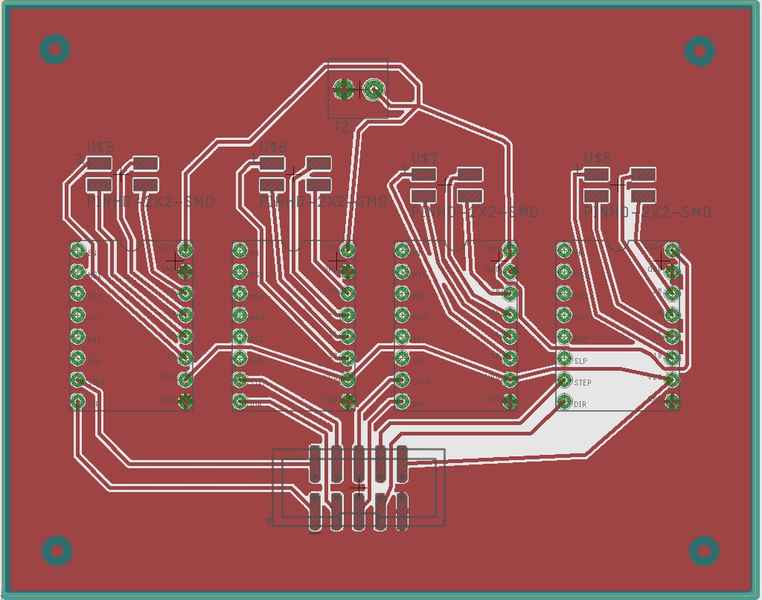
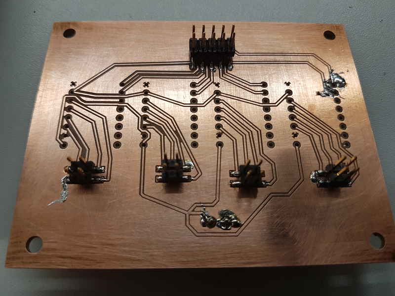
Designing motor controller board
After this, I started to work on the motor controller board. I used the measurements of the commercial motor controllers (Reprap Stepper Driver A4988) and put 4 of them in row. The board has only the placement of the controllers, 2x5 pin header, connectors for stepper motors, terminal for 12 V power supply and lines for the signals, VCC and GND. The size of the board is 9 cm X 7 cm.
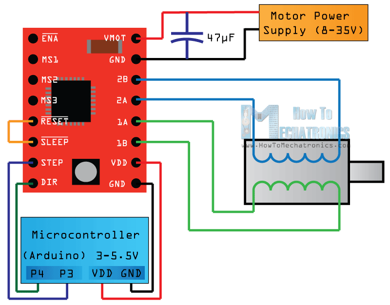
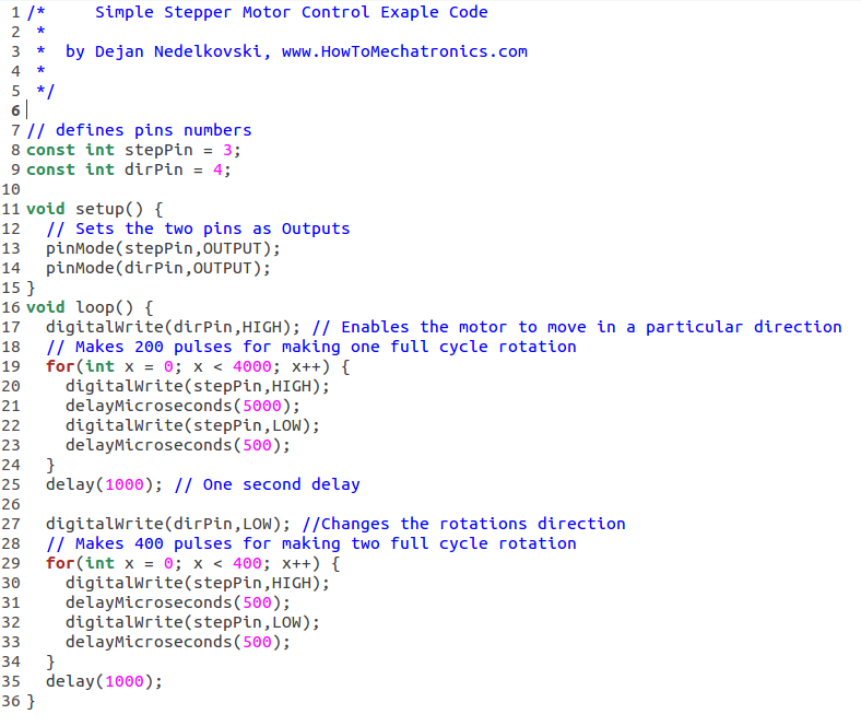
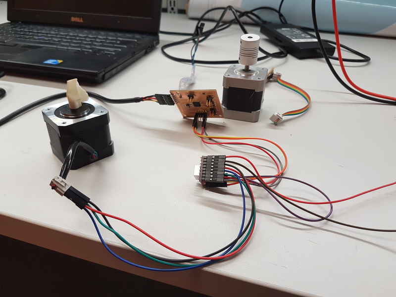
Running a stepper motor
I programmed the microcontroller with Arduino IDE. It has all the necessary tools for the programming in it for ATmega328p microcontrollers, which makes the programming straight forward process. I used a guide I found online. The guide had instructions for connections and the code for the testing as well. In my case the green wire is the 1B, blue is 1A and red is 2A and black is 2B.
Reflection on this weeks assignment
I really enjoyed this weeks assignment. There was plenty of learning and I understand a lot more about stepper motors and their control. I had never used stepper motors in any project and it was really interesting and opens a lot of possibilities for the future making. This supported my final project very well, but naturally I need to create the code for the pump control, but now I know what I need to do.
The files used in the assignment are shared below:
StepperDuino board
StepperDuino schematics
StepperDuino traces
StepperDuino traces milling rml file
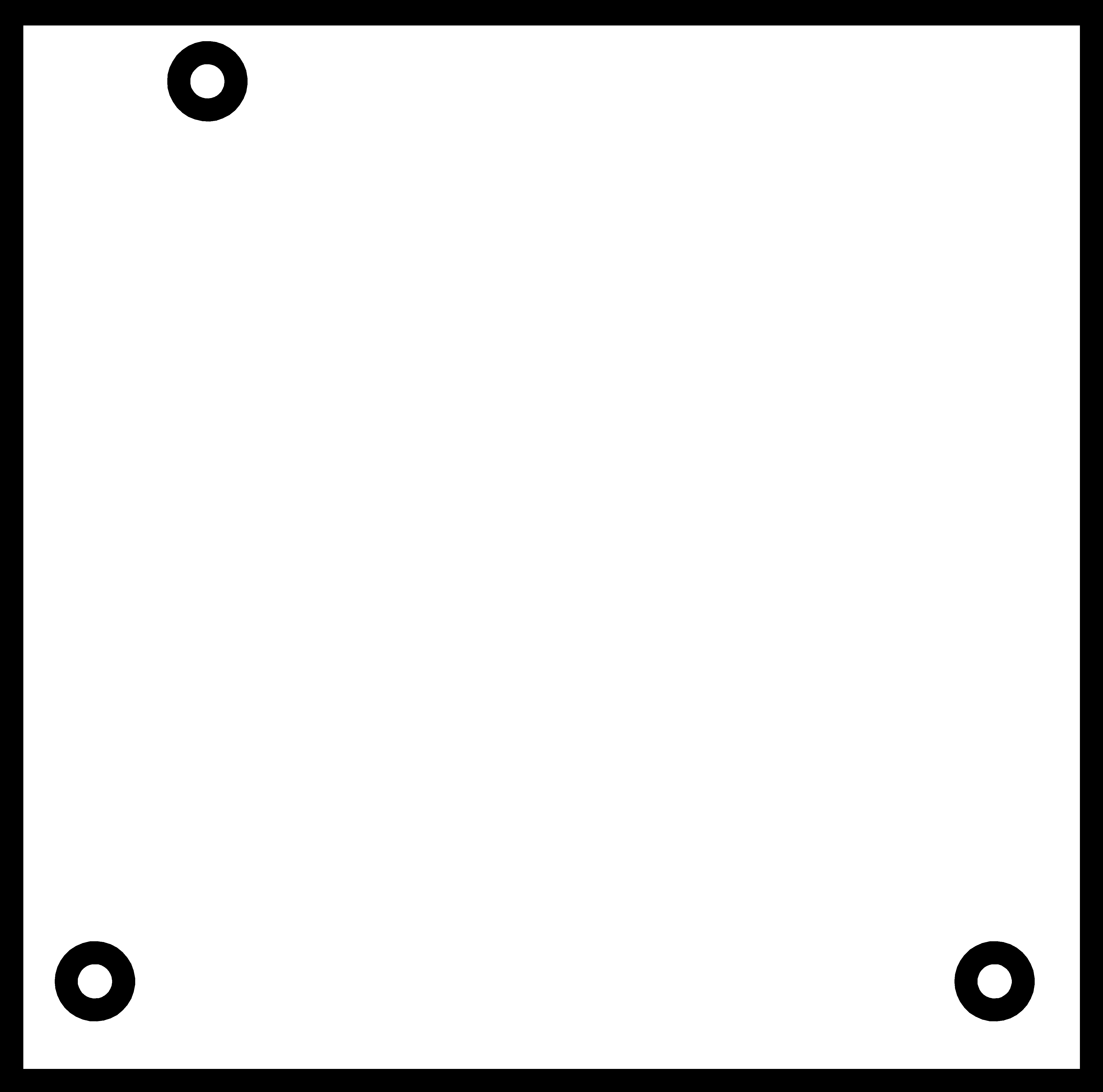
StepperDuino_outline
StepperDuino outline milling rml file
StepperBoard board
StepperBoard schematics
StepperBoard traces
StepperBoard traces milling rml file
StepperBoard pads
StepperBoard pads milling rml file
StepperBoard_outline
StepperBoard outline milling rml file
StepperMotor.ino