Assignment 15: Mechanical design
Assignment:
Group assignment:
- Design a machine that includes mechanism+actuation+automation
- Build the mechanical parts and operate it manually
- Document the group project and your individual contribution
Machine design
This week we only had a group work, which was nice change to normal routine. Our instructor Eino suggested that it would be interesting to work with a machine that measures surface evenness. Those of us who were intrigued by the idea started a group. The other group members are Kati Pitkänen and Jari Uusitalo. The group work is presented in the Machine design.
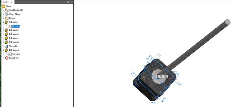
We started to create the basic design as a group and I started to create 3D model of the machine with Autodesk Inventor 2018. I had never designed anything like this, but previous years machines made it easier as we took them apart and studied the structure. Then we made a rough sketch by hand and I started the work. At first, I made a model of a stepper motor we had available
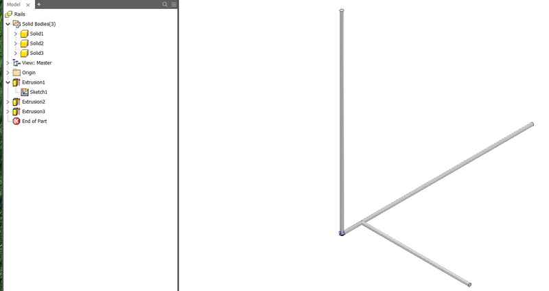
Secondly I created linear guide rods for each axes
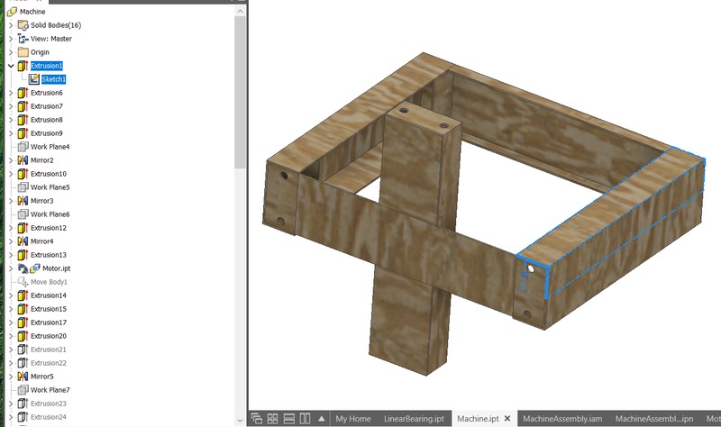
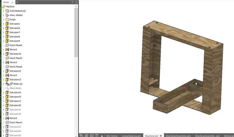
Then I created the main body of the machine, which consisted of the X and Z axes.
It was straight forward job. The outer structures with motor holders were designed first and then I moved to moving parts.
I mirrored the whole thing over two planes.
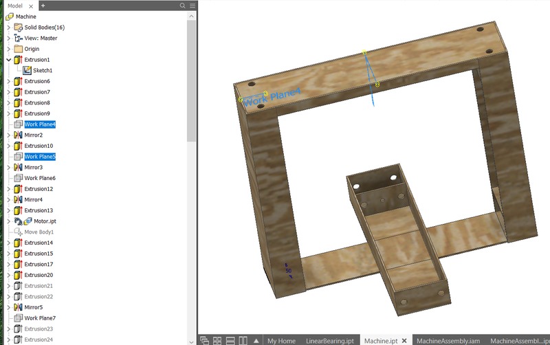
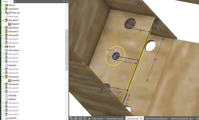
I left 0.5 mm space between the walls and the moving parts. Inside the moving parts, I left space for the lead screw nut. I made holes for all the linear guide rods and the linear screw of the stepper motor.
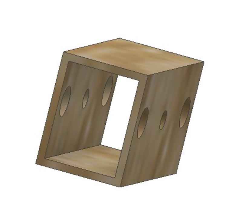
Moving X-axis is presented below
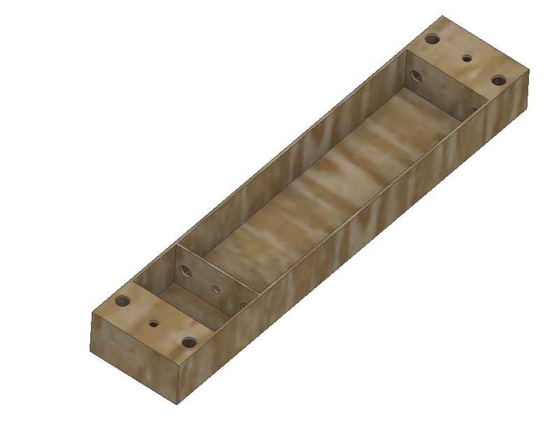
Moving Z-axis is presented below
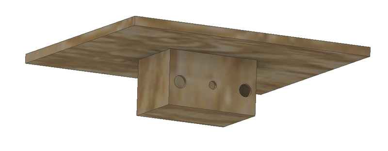
When I was done with the main body, I started to design the Y axis. The basic structure of it was similar to the other axes, but the moving part needed to be connected to a plane surface, which is used as a measuring plane.
This structure needs to be sturdy and even. At this point, I only designed it to be connected to the moving part with tabbed connection in the sides, but for the actual machine we decided to make tabbed holes through the surface to make it as steady as possible with simple design.
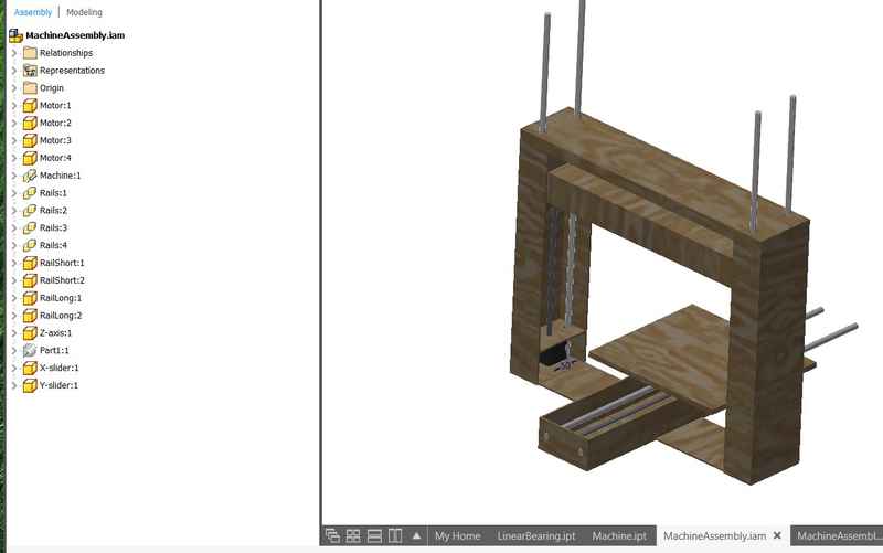
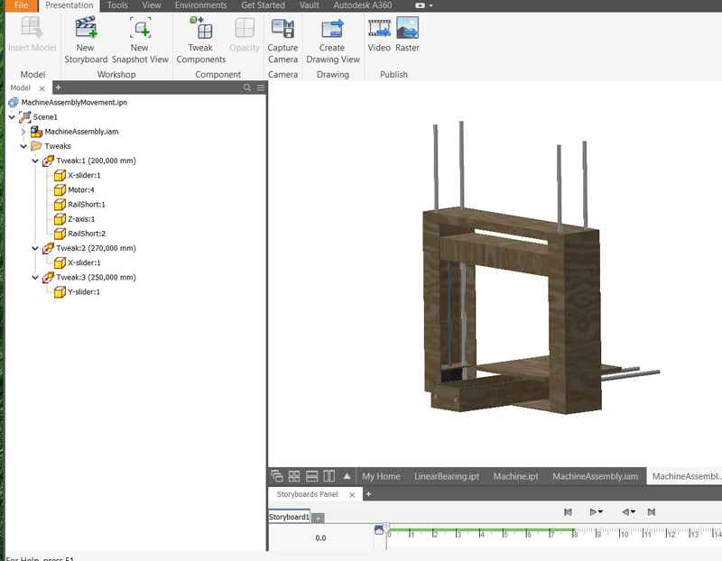
After I was done with the 3D modeling, I sent the files to other group members and Jari started to make all the pieces laser cuttable with tabs. Meanwhile, I made an animation of the whole machine with all of the moving parts in motion. I had wanted to do that kind of thing for a long time, but finally I got a chance to actually make it. The process itself was as fun as it sounds. In the Autodesk Inventor 2018, I separated all the moving parts to their own parts and made constraints with minimum position for all of them in the Assembly.
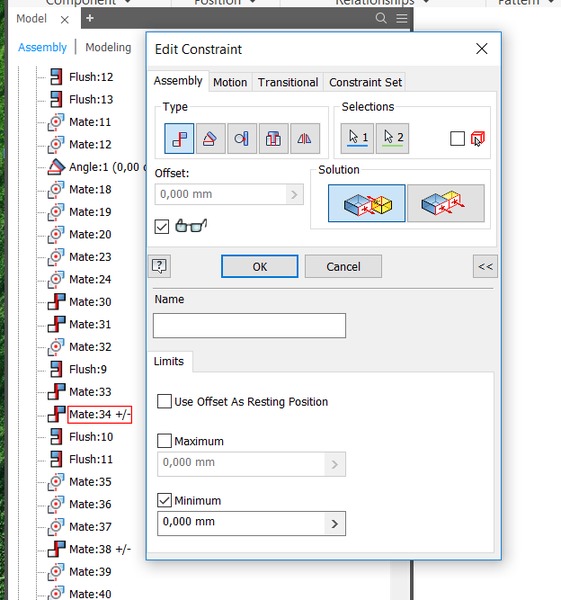
Then I right clicked on each of the moving parts and I removed all the ground selections. After that, I right clicked on the constraint where minimum distance is selected and pressed drive, selected the maximum and started to animate.
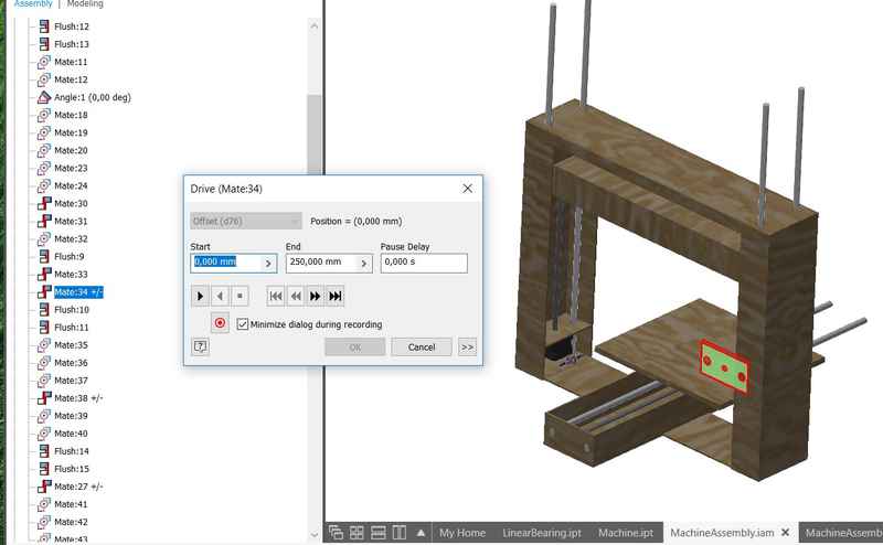
In the first try, I forgot to ground the main body and the whole machine started to move, but then I grounded it and things worked as they should. Then I opened the assembly in Presentation mode, selected a camera position where I could see all the movement and made tweaks for all of the moving parts. Tweak is needed to make parts move a predefined distance during a desired period of time.
Then I pressed play and all the movement could be seen. After I was happy with all the settings, I changed materials for all of the parts. Structures were made out of plywood, rods of aluminium and motors of black steel. Then in the view settings, I put all the shadows on and changed view to realistic and made ray tracing. Then I updated everything in the assembly and presentation and made the actual video. At first, I made an avi video, which was about 500 MB and then I made the video in WMV format, which only took 396 kB and I changed it to mp4, because WMV is not used in any web browser. Video is shown below.
Then Kati made the laser cuts and we realized that we need holes for motor screws and lead screw nut screws. These small pieces were remade with holes. The assembly was fun. The laser kerf was very well set (100 µm) and the parts fit together nice and tight. It was like putting together an IKEA furniture without a guide, but of course it was easy, because we could look at the 3D model and the laser cut parts were divided between the main body, Z-axis and Y-axis. Jari was not happy with the upper part of the main body and we remade that. We had only 8 pcs of plastic linear bearings and because we needed more, I created a 3D model of one and we 3D printed the ones we needed.
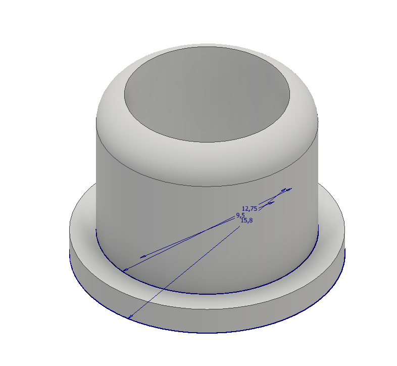
They were a little bit too tight in the beginning, but after sliding them a few times on the linear guide rails, they started to move smoothly.
Reflection on this weeks assignment
This weeks assignment was really fun and it was a nice change to work the whole week as a group. The ideas are much more interesting and there are plenty of possibilities to choose from in a group. All the obstacles are crossed more easily and the divided responsibilites make life easier. After this week, I understand how to make a machine move with lead screw and linear guide rails.
The files used in the assignment are shared below:
Week15Files.zip All the 3D modeling files that I created during machine week.