Assignment 16: Machine design
Assignment:
Group assignment:
- Actuate and automate your machine
- Document the group project and your individual contribution
Machine design
This week we continued the group work on machine design. The other group members are Kati Pitkänen and Jari Uusitalo. The group work is presented in the Machine design.
Last week we designed a machine without actuation or automation and now we were to design it to do our aim, which is to measure surface evenness. We divided the tasks between us and I started to work on the sensor for the surface measurement. Originally, Jani suggested for us that it could be made with piezoelectric needle, but there was quite a little information on that and no needle as well. Luckily, Bas suggested that we can make a press button, which can be lowered on the surface and when the circuit is connected, we can read the position in all axes. So I started to create this button. It was surprisingly hard to design a push button, even though I understood what I needed to do and how it should work. I found a web page http://machineryequipmentonline.com, where was a nice picture about the operating principles of a push button.
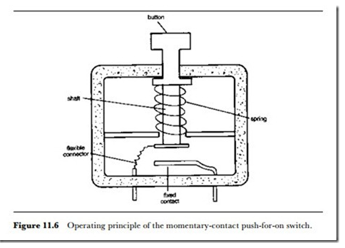
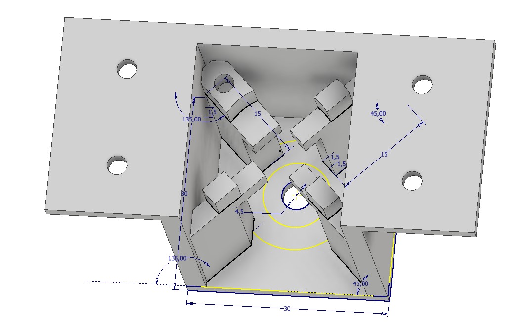
Based on that picture, I started to create our button. Button needed a casing and I designed that at first. In the first try, there was no back wall and the printed part was wobbly and I didn't realize to put enough space between the support structure to make the button shaft fit through. In the image, the final structure is presented where these things were taken into consideration. It has also a placement for a small metal plate and a screw, which is connected to signal cable.
At first, I created a button very similar to this and realized that the button part doesn't fit between the support and putting a spring around the shaft was really hard. But Jari had an idea that we just bend the structure, add a needle for spring to stay still and that was the first button, which operated quite ok, but wasn't really a good one.
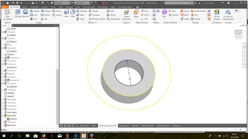
Then I created a button shaft. It was simply a shaft with a fixed collar to hold the button inside the casing and to hold the spring in place. In the upper part, I created a moving collar, which slides along the shaft and moves with the spring, when the button is pressed. In the top, I needed to create a locking mechanism and studied different kinds of 3D printed press-fit parts. It was surprising that the press-fit worked in the first try and didn't break. I was already designing alternative option using screws, but since it worked, I decided to go with that design.
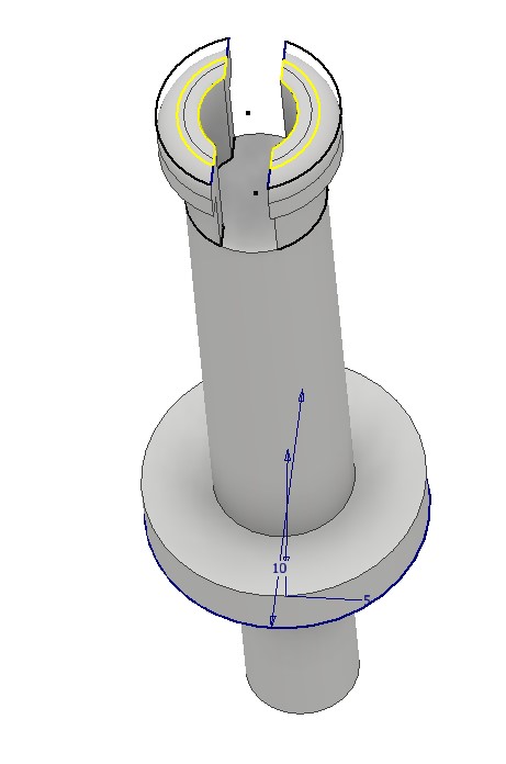
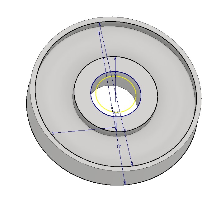
The collar around button shaft, is simply a wheel, with 0.5 mm bigger diameter than the shaft.
To lock the button shaft down, I created a locking mechanism, which also keeps the button in straight line. It has also a place for the ground wire connection with a washer.
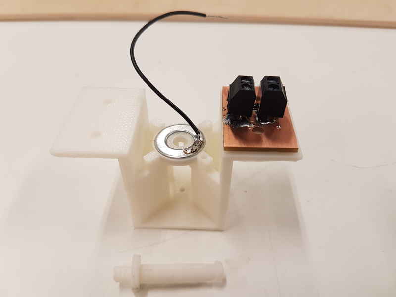
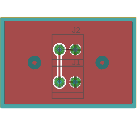
I created a terminal board for the cable connections. It had only two terminals on it to keep the wires inside the sensor in place and the moving wires are connected to other terminal. This was done to make the sensor less vulnerable to machine movement.
Video is shown below.
Reflection on this weeks assignment
This weeks assignment was really fun yet surprisingly challenging and it was nice to continue to work as a group. I thought that button would be easy to design, but it was harder than the rest of the mechanical parts.
The files used in the assignment are shared below:
Week16Files.zip All the 3D modeling files, board files and milling files that I created during machine week.