Assignment 3: Computer-Aided Design
Assignment:
Model (raster, vector, 2D, 3D, render, animate, simulate,...) a possible final project and post it on your class page.
2D tools
The first tool I wanted to use is raster tool for image manipulating called GIMP. The view in GIMP after start up with blank page looks like this: 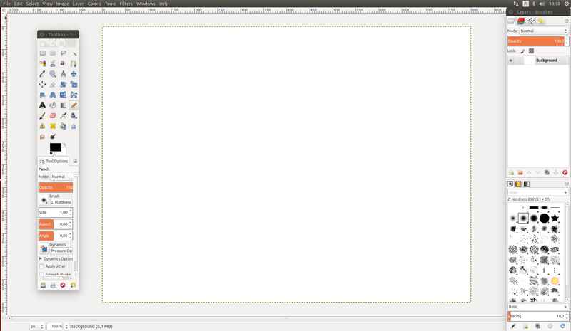
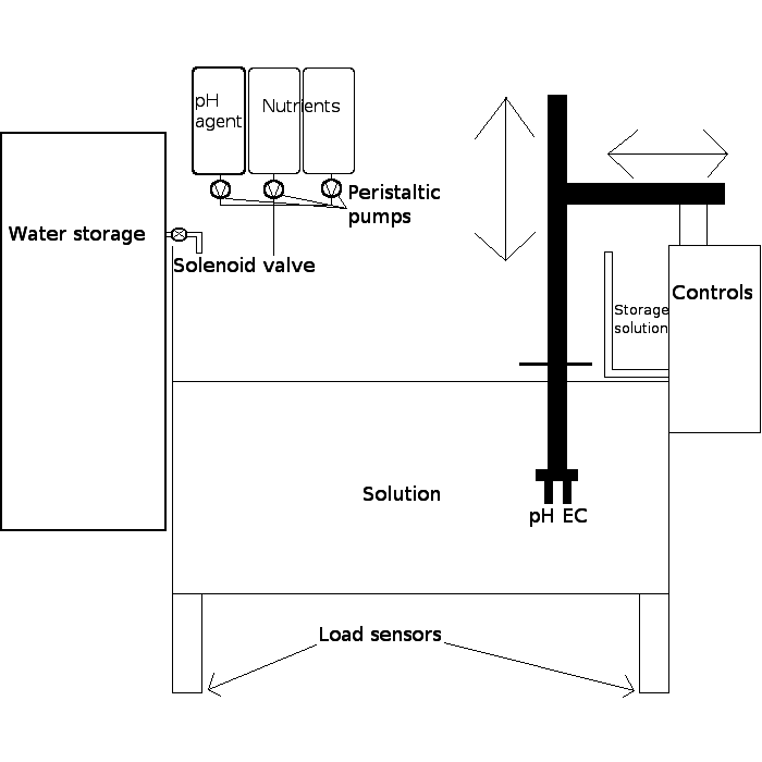
For my drawing, I used lines to drew the box and the water level. To create the shape of the pH-EC meter, I created six different boxes. Two boxes for electrodes, two for the shaft, one for the beam and I created one box for the lid as well. All of the text is written with text tool. It is nice because it creates its own layer and can be edited later. 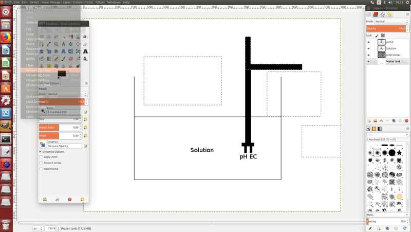
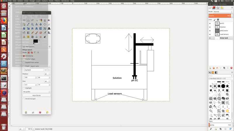
Layers are very useful tools in design, because you can apply several layers on top of each other and they don't mess up other layers in the process. I created layers for different parts and labels, which made it possible to move them in relation to each other, without causing problems later. 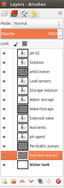
3D tools
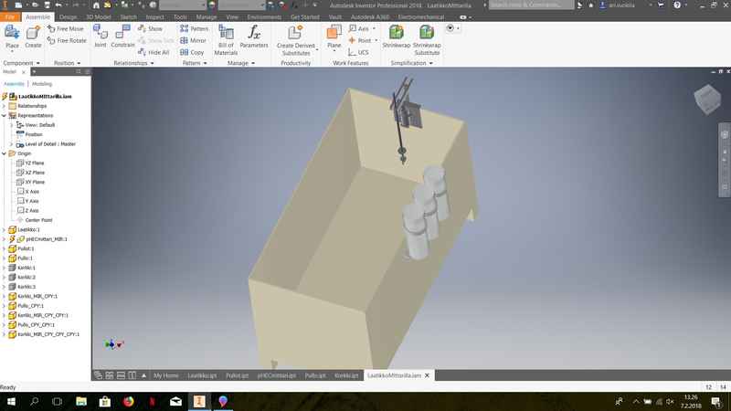
After I created the 2D-version of the plan, I started to work with different 3D-modeling tools. At first, I installed Autodesk Fusion on my computer, because we worked with it during the local lecture. The lisence was only for one month, so I switched to a more familiar program Autodesk Inventor Professional 2018. The Fusion was simplified version of the Inventor and I didn't enjoy the restrictions it made for my work. The use of constraints seem to be much easier in Inventor, which makes it much more useful, when you are working with complex geometries. I started to go through my final project part by part. At first I created the storage vessel for solution. The storage vessel contains holes for the mounting of pH-EC meter and bottle stand for nutrients and pH agent. The shape was sketched in 2D, extruded and made into a 4 mm thick shell.
The sketching is 2D modelling on a plane, which can be then extruded in the 3D in plane normal direction. When you use extrude tool, you have to select features from a sketch, which you want to extrude. Then select how much you want to extrude, which direction you want to extrude and then you can select whether the extrusion is used to add new solid, join it to existing solid, cut it from existing solid or to intersect it with existing solid. Shell tool is used to remove material from a part interior or to create hollow cavity with walls of a specified thickness. You have to select, which walls are to be removed and to select the wall thickness. The shell can be made on the inside, outside or equally on the both directions. I created a rectangle in sketching, then extruded it as a new solid rectangular cuboid and then used shell tool on the top surface of the box to create 4 mm thick shell. On the walls, which required the holes for the mounting, sketches were created and extruded through the part. The holes are 50 mm apart from each other. 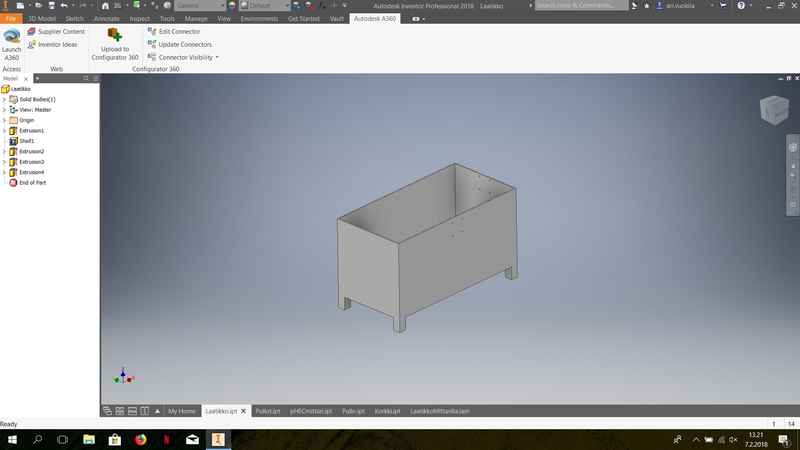
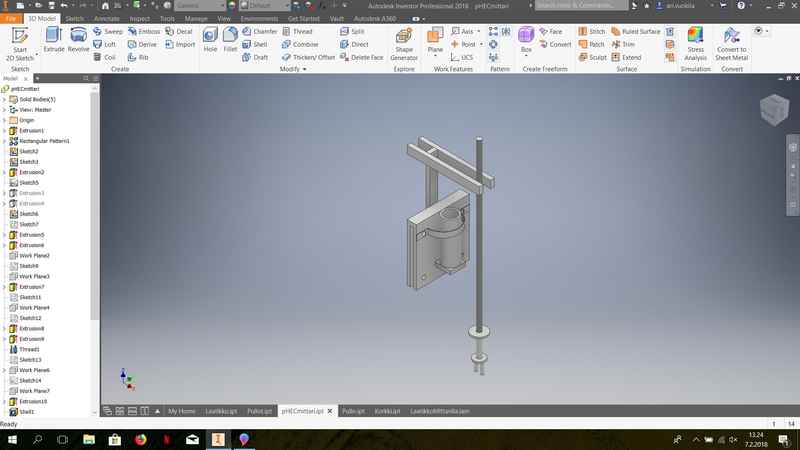
The bottle holder part was made next. It is quite simple design and it is only meant to hold three 350 ml bottles. Two bottles of nutrients and one bottle of pH agent. The shelf for the bottles is attached to a mount and to keep the bottles steady these rings were created. They were swept along circles, with diameter of 52 mm.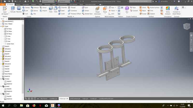
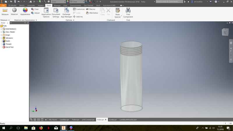
The bottle cap has threadings in it and hole in the center, where silicon tubing is added. Peristaltic pump is used to dose the amount of nutrients and pH agent to solution through that hole. The cap is supposed to hold the peristaltic pump, but as I do not know the dimensions yet, it is left for later time. 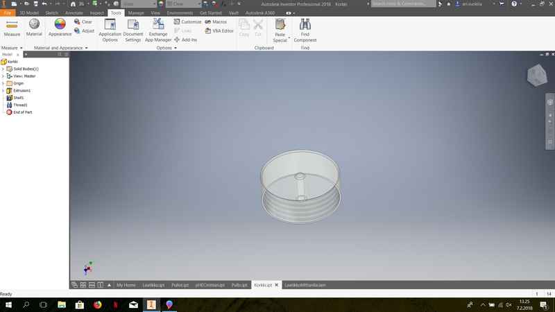
The assignment was really interesting, but I hoped I had more time to get to know new tools. Now I have Solidworks on my computer and I created Onhape account as well. I plan to try them out later in the Fab Academy, but this week was so hectic that I only had time to fill minimum requirements. I have been working with CFD for about 8 years and I have been creating geometries for the CFD modeling with several different programs (gambit, freeCAD, Gmsh, Salome, Ansys designmodeler). The one I enjoy using the most is Autodesk Inventor, but I have never had any courses about CAD, so my working methods may not be the most efficient ones, but I have always gotten everything done in the end. During my thesis work, I used Inkscape to create vector graphics for my PhD thesis. During the last lecture, I learned that it can be used with much more than just change raster to vector graphics.
Update on 3D tools
I tested the Solidworks 3D modeling tool and made a simple test geometry with it. When you open Solidworks part, it automatically goes to sketch panel.
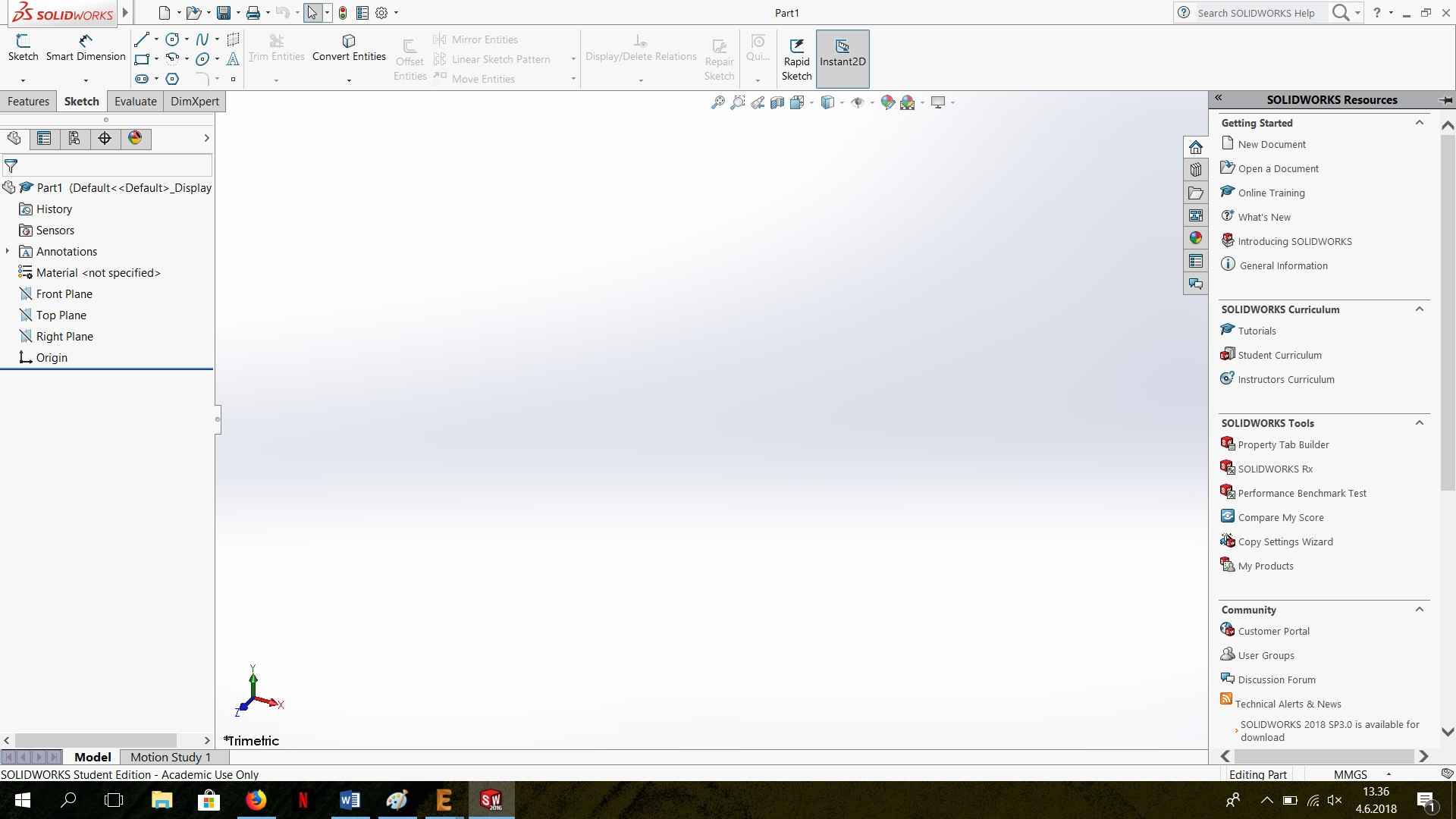
In there you can select Sketch and which surface the sketch is going to be made. The user interface is quite different in the Solidworks compared to Autodesk Inventor. Most of the selections are done in a vertical menu in the left side and it took some time to get used to, but at the same time it is very useful and you can directly enter the parameters in there.
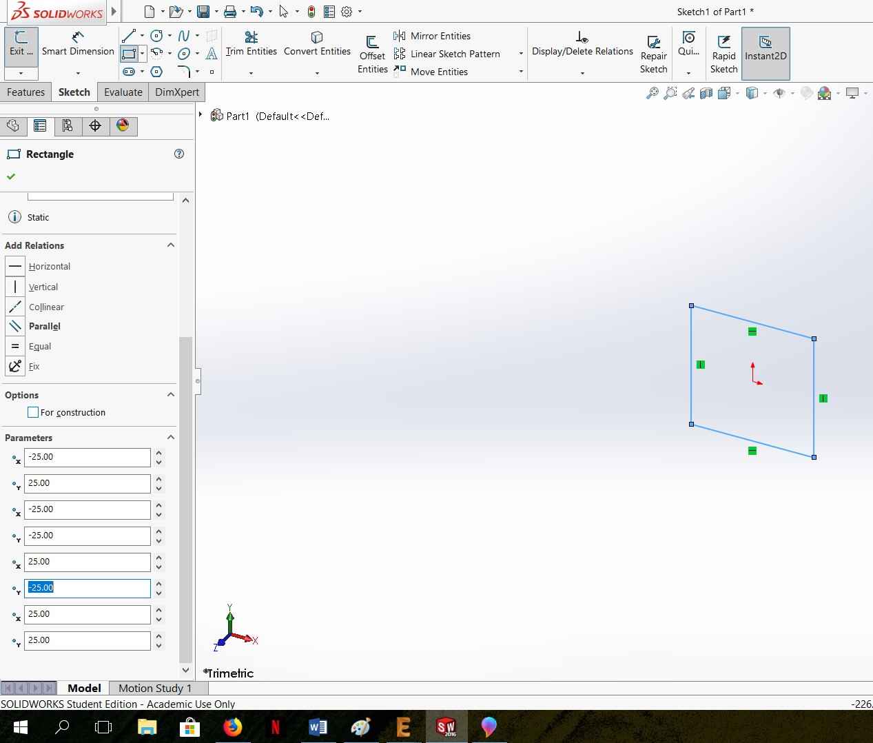
I created simple rectangle, closed the sketch and went to Features menu and selected Extruded boss/base. In that case too, the selections are opened in the left side, but you can push and pull the extrusion as well and the extrusion dimension is showed as a measurement on the plane.
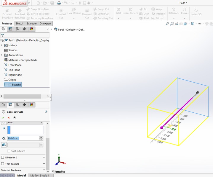
Even though this can be done in Inventor as well, I think the Solidworks tool was easier and more clear to use. Then I created a rectangle sketch on the surface of my previously created solid object.
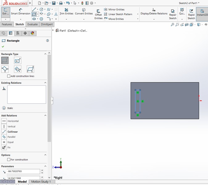
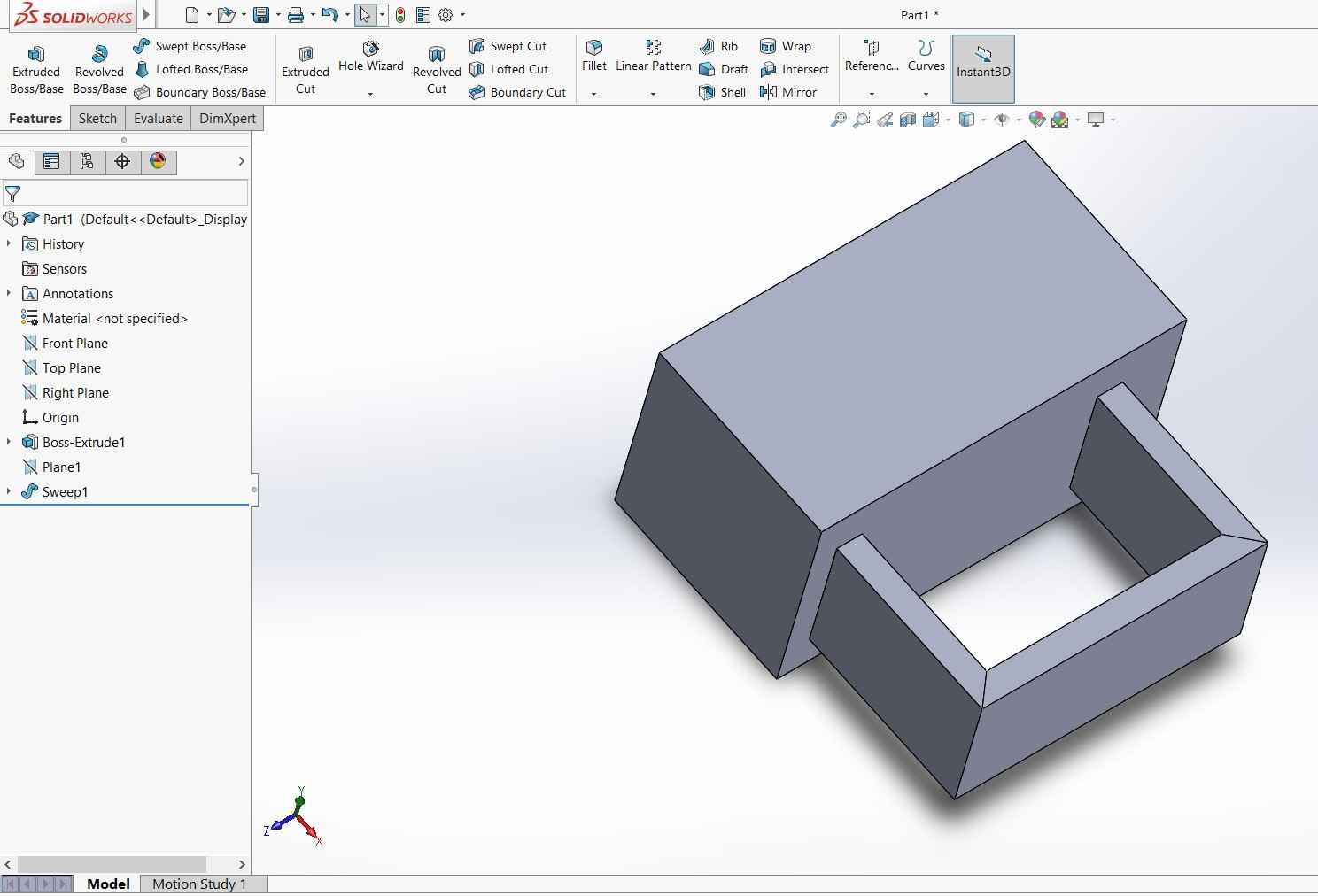
Then I selected reference geomery in the upper horizontal menu and plane. With that tool you have to select three reference points and it creates a workplane. I created a workplane normal to my second rectangle and drew lines to make a path for my Swept boss/base. I used that tool to create swept solid object.
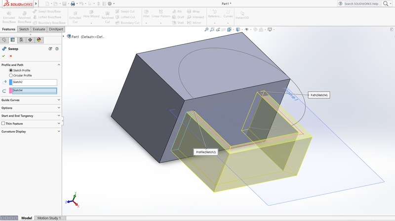
It was quite easy and the logic behind the Solidworks is close to Inventor. It only took some time to figure out where everything are and what each function is called in the Solidworks.
The biggest problem with Solidworks is that it requires a lot of memory. My laptop was all the time telling me that the memory is low and it was very laggy. With Inventor, I have never had that problem.
The files created in the assignment are shared below:
FinalProject.xcf GIMP file for the final project planning
FinalProject.zip Autodesk Inventor files for the complete assembly. Includes all the parts and the assembly file.
STLFiles.zip STL files for the complete assembly. Includes all the parts and the assembly file.
TestObject.SLDPRT Solidworks file for the test object.
TestObject.STL TestObject from Solidworks in stl format.