Assignment: Group assignment: - Test runout, alignment, speeds, feeds, and toolpaths for your machine Individual assignment: - Make something big
Designing something big
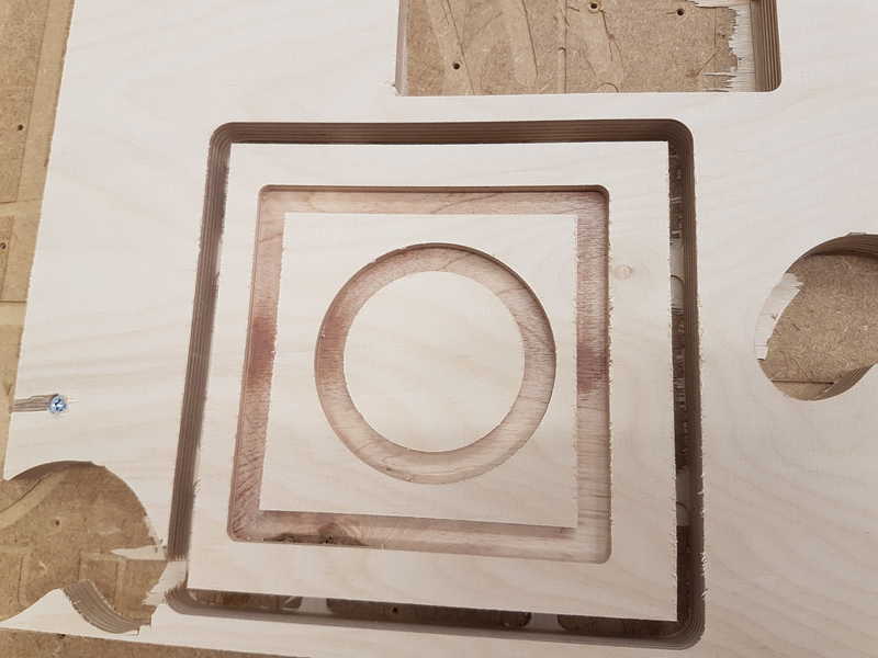
We started to learn about CNC machining with our local instructor Eino Antikainen at 8.3.2018 at 9 am. We used was Autodesk Fusion 360 to create needed files for the machine. We created simple geometry, which could be used for the group assignment as well. It had rectangular and circular 10 mm inlays and the part itself was rectangular and it was to be cut off from the stock material. The process is explained in the group assignment page .
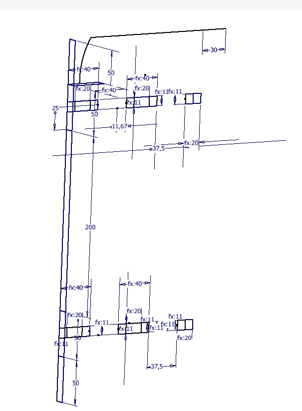
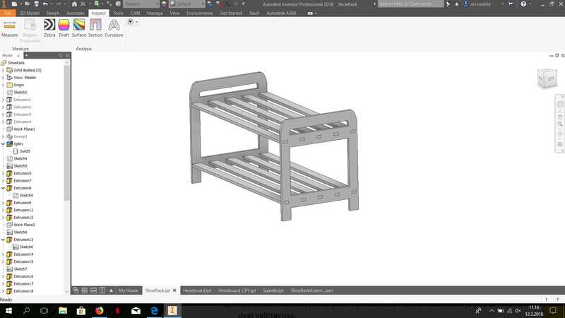
I have been searching for a shoe rack that fits in my closet for several years without success, because the size of the commercial ones are always too big or way too small. So I decided to make a custom shoe rack. At first, I measured the closet to get the accurate measurements. Width is 76 cm, depth is 45 cm and maximum height is 45 cm. I sketched a rough drawing by hand and then moved to Autodesk Inventor 2018 to create 3D model of the shoe rack. Because the Inventor needs CAM tools for this task, I installed the Autodesk HSM with simple web installer. The drawing is very simple and I chose to make 1/4 of the shoe rack and mirror it over two planes to avoid unnecessary steps.
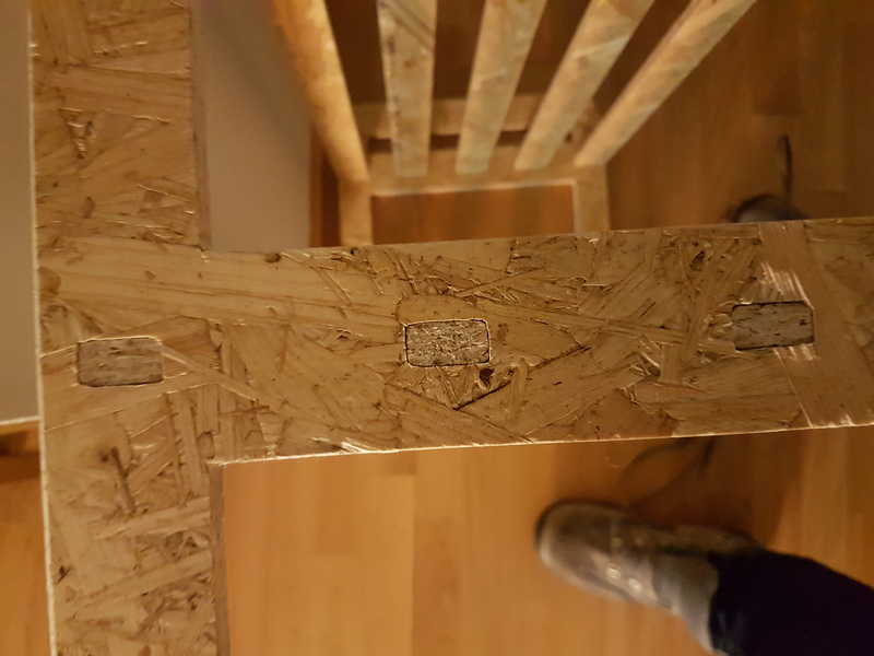
I made the model parametric, because I was not sure about the material thickness and didn't want to switch all the measurements by hand after the exact measurement of the material. The material was 11 mm thick Oriented Strand Board (OSB). I decided to make the joints between the shoe rack end parts and the spindles rectangular holes even though I knew that I have to file the corners for them to become actually rectangular.
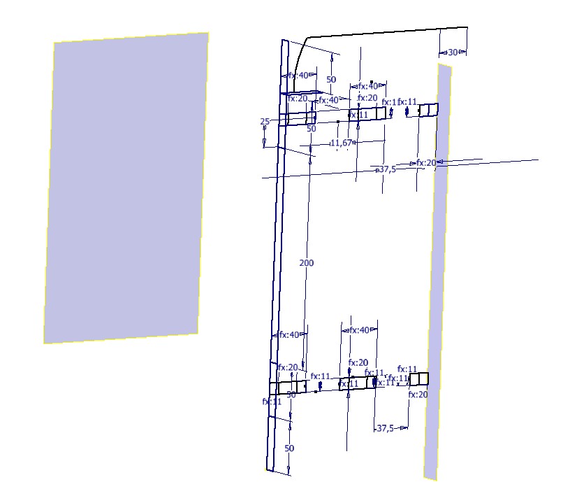
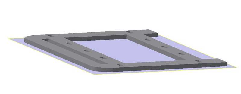
When the shoe rack was modelled in 3D, I created parts of the end part and one of the spindle and opened them in assembly.
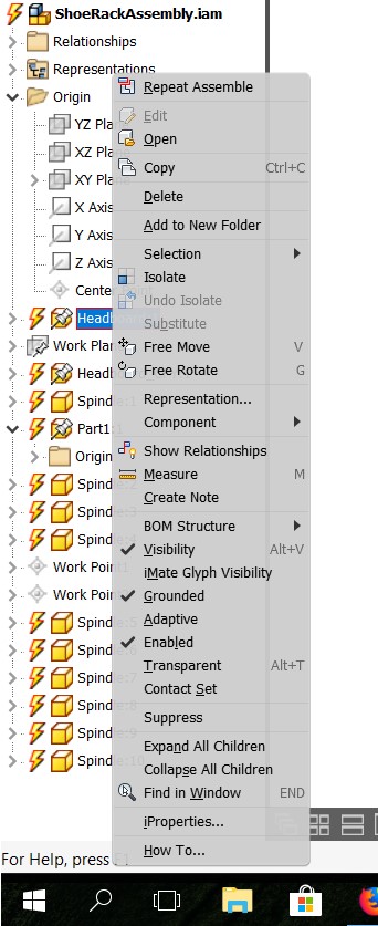
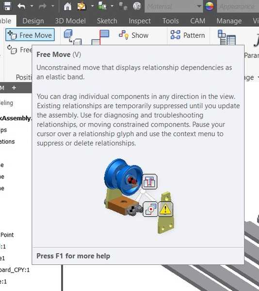
In the assembly, I removed the grounded selection from the parts to make them be able to moved freely.
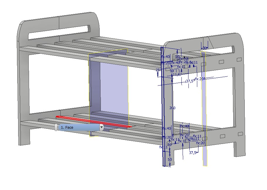
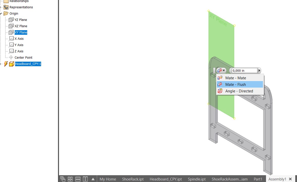
In the Assemble -> Relationships -> Assemble, I chose Mate-Flush and the bottom face of the parts and the XY-plane to make the part bottom face lie on the XY-plane.
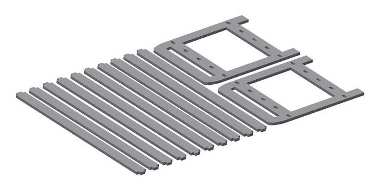
Then I copied the parts and moved each part to their places. I measured the distances between parts to make sure that the tabs and the tool fit between them and a little bit of material is left for the tab connection. I used 20 mm distance between parts.
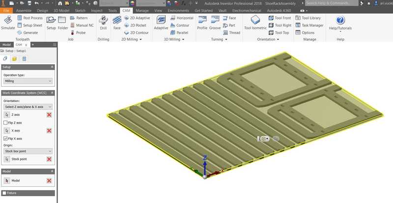
When you watch the assembly from the side, which you have selected as the bottom plane, the copied parts are automatically set on the same plane and with free move the z-direction is not changed. When all the parts were placed on the XY-plane, I selected CAM tab from the Inventor and started working on the instructions for the CNC router. At first, select Setup and edit to set the work coordinate system. Always select the lower left corner on the stock top with Z-direction up and X-direction to width and Y-direction for lenght.
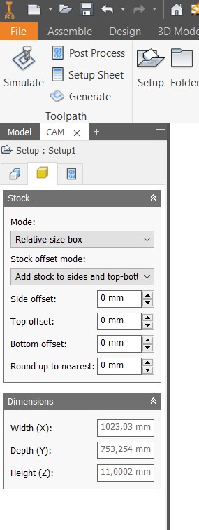
After that is setup, select the second tab called Stock and switch All the offsets to 0 mm and press ok.
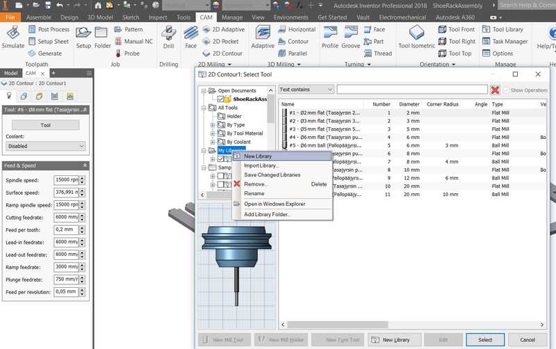
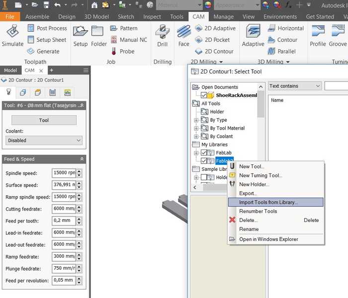
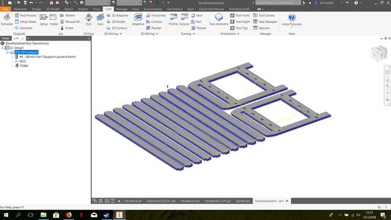
Then depending on your work, you can select 2D Pocket (For the roughing operation (create patterns below stock top level)) or 2D Contour to cut parts off the stock. I only needed 2D Contour for my work and selected that one. Right click on contour and press edit. To select tool for the milling, press tool button. Because our Fab lab has its own tool library (FABLAB ROUTERI TOOLS 2018-2.hsmlib), I created My Library by right clicking on the My Libraries and selecting new and naming it FabLab. Then right click on the created library and import library from the place where you put the file.
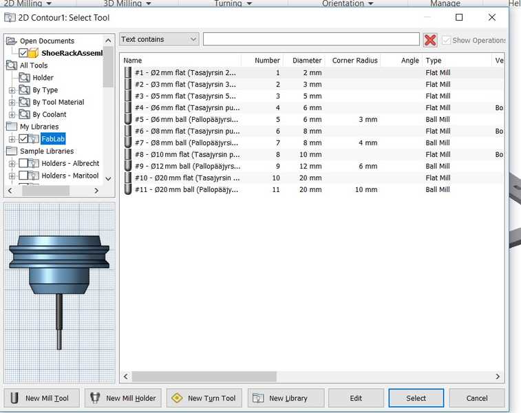
I used 8 mm flat tool for my project and selected it from the list. Tool should be now visible in your view and the angle correct. Go to Geometry tab and select it. Select all the geometries that you want to cut out. Then select Tabs that you want to use.
I used rectangular tabs with 8 mm width and 1.5 mm height and the distance was 64 mm.
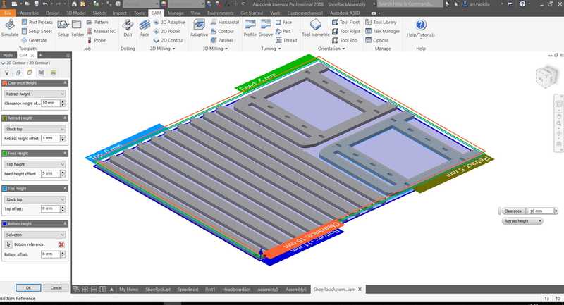
The tabs are used to prevent the parts moving during the cutting process. After that move to Heights tab and select the Top Height and Bottom Height. The top height can be your Stock top and the bottom should be chosen to be the bottom of your stock. Other heights just have to be above your stock material so that the tool can move freely above it.
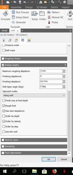
Then move to Passes tab, where you choose Multiple depths and set Maximum roughing stepdown to 3 mm and Use even stepdowns. Remove Stock to leave.
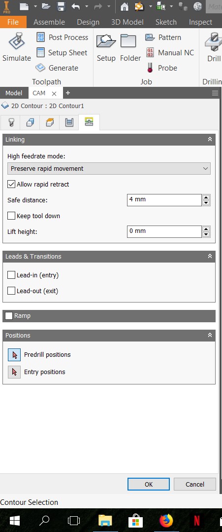
Then move to Linking tab and remove Lead-in and Lead-out selections. Then press ok.
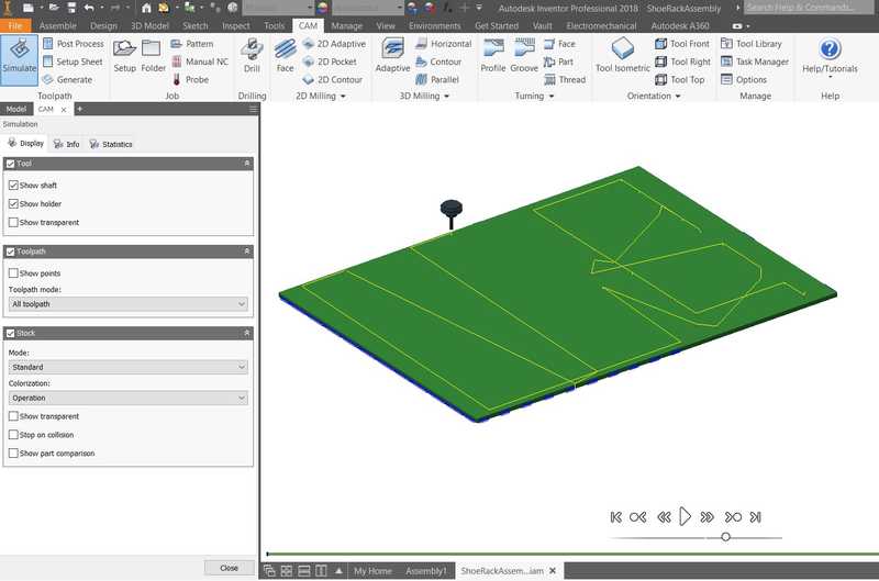
Now all is set and you should simulate the milling process. Press Simulate, include Stock and press play button. The speed can be varied by moving the ball along the line below play button. In the simulation statistics you can see the Machining time. In my case the time was 23 min and 57 seconds.
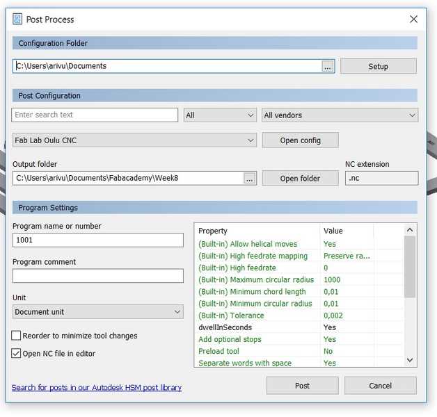
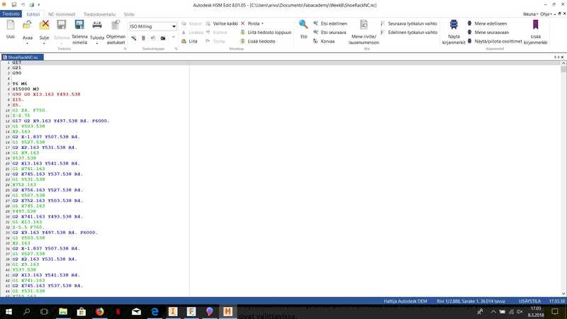
When you can see that everything goes as planned select Post process. For the configuration, you should select the CAM post processor file for your local router (FabLabCNC.cps). Post process creates nc-file in G-code, which can be used in the local CNC machine.
CNC milling
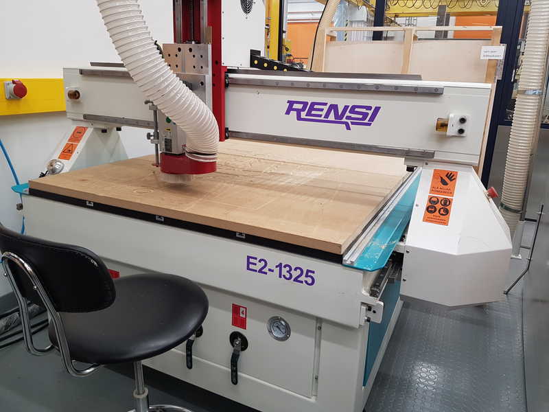
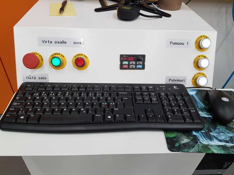
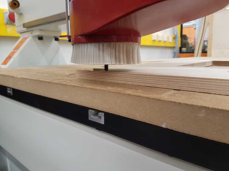
The CNC router in our Fab lab is Rensi E2 1325.
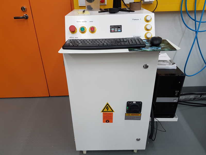
When you start working with it, switch the computer on, turn the main switch on, press power on and start the both pumps 1 and 2 and also the vacuum cleaner.
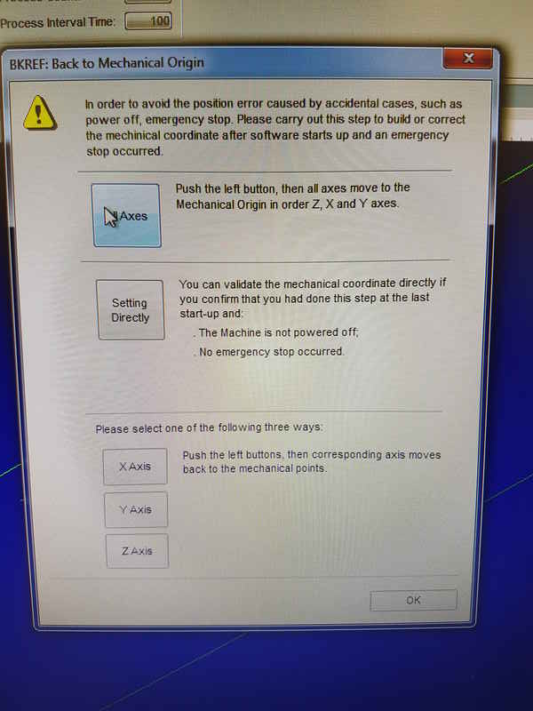
After the machine is turned on, open the NcStudio where pop-up window presents itself that says "back to mechanical origin". You have to press All Axes button and the machine will move all axes to the mechanical origin or machine zero. When the machine is finished press ok.
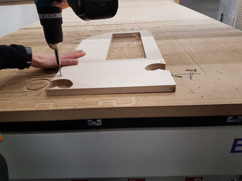
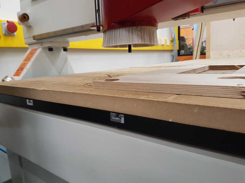
Put in your material in the machine and attach it to table (sacrificial board) with screws to avoid its moving during the milling process.
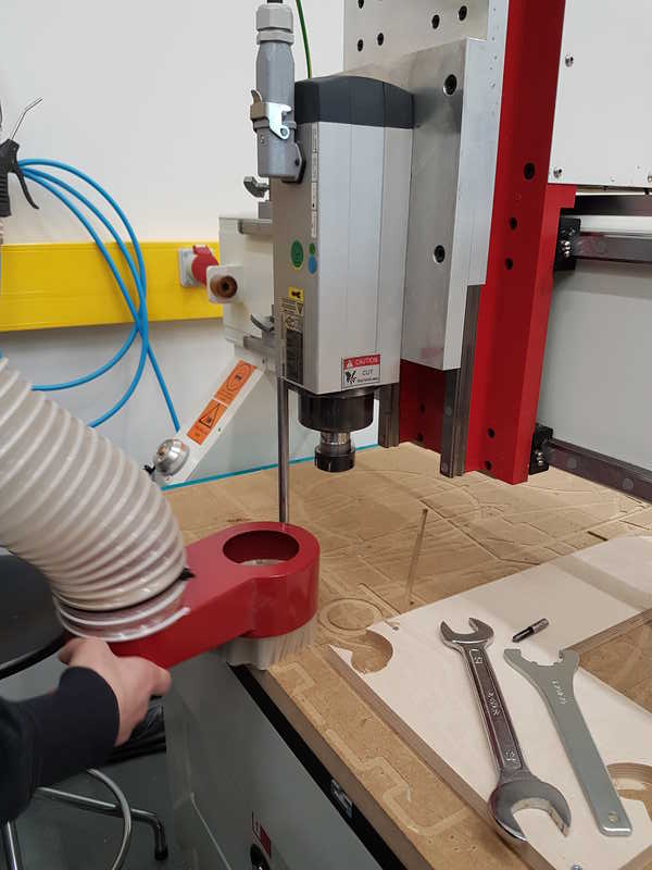
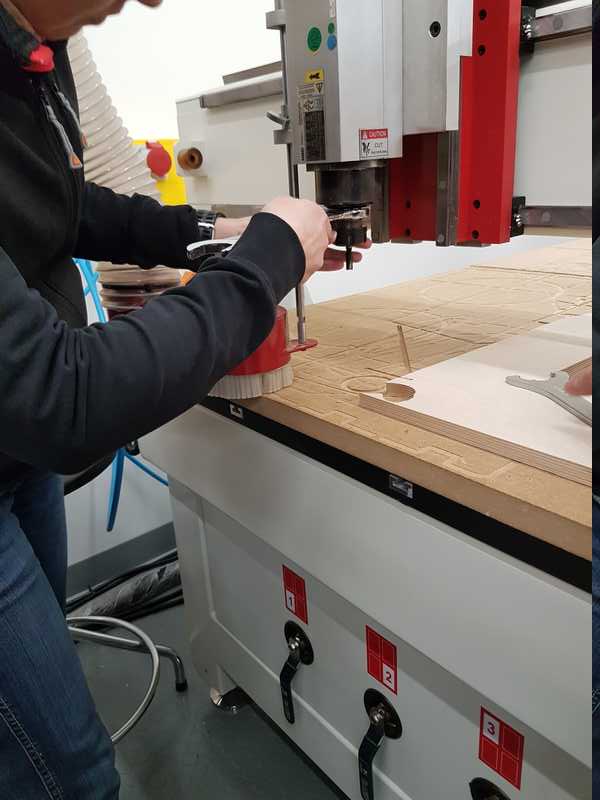
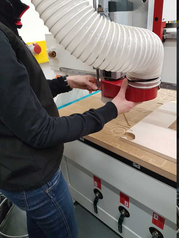
Move the CNC router head in a position where you can put the milling tool in. Machine can be manually moved in two ways, either use XYZ arrows in the NcStudio or you can use a controller, where you select the axis (x, y or z) and speed of the movement (x100, x10 and x1) and do the moving by rotating a crank. Remove the spindle dust cover from CNC router head by using two butterfly screws on the side.
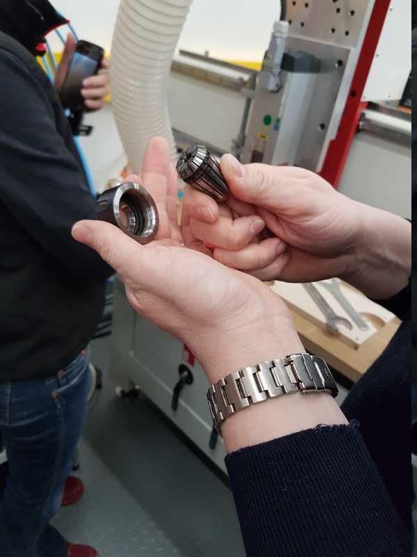
Put the selected CNC tool collet (size depends on your tool diameter 8 mm in our case) in the collet clamping nut.
Put it in its place and screw it on loosely and insert the milling tool (in this case 8 mm).
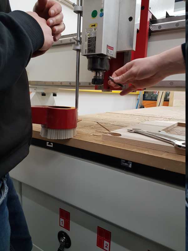
Screw it tightly on to avoid its movement during the milling process.
Add the spindle dust cover back to machine.
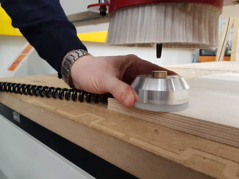
Then set the starting point for the milling process. You can do it automatically or manually. With automatic setup, you have to use special sensor which detects the milling tool, when it is lowered to its surface.
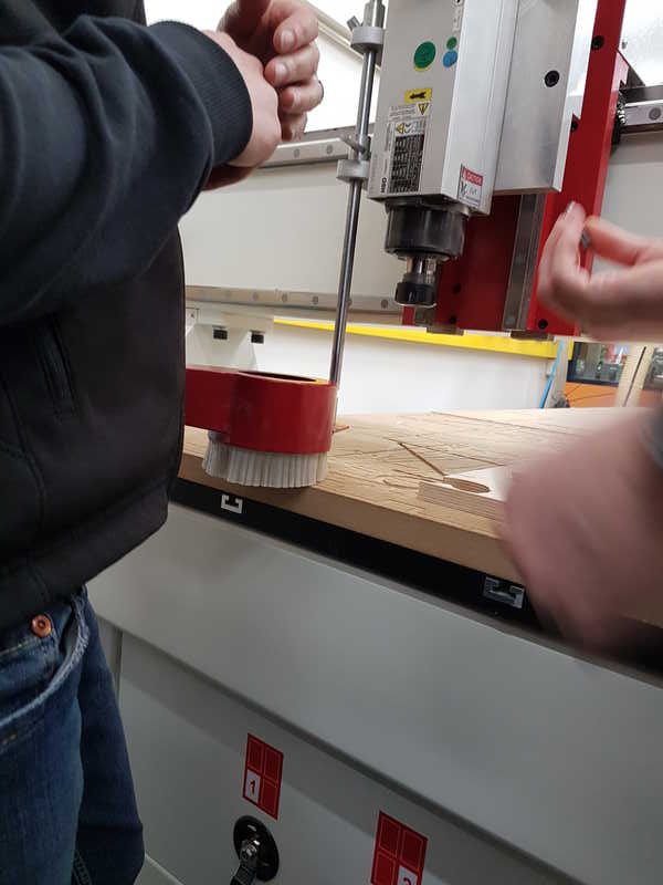
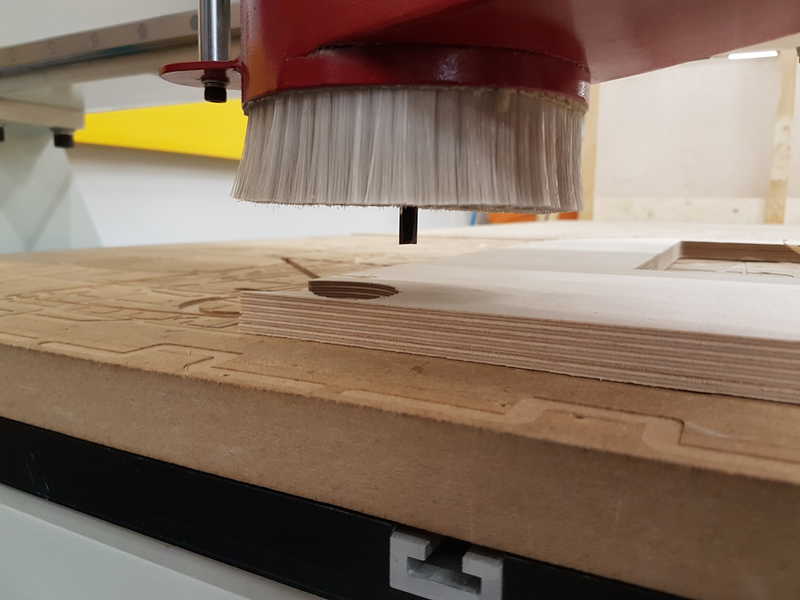
In the manual setup, you turn the spindle on with 10 % setting and carefully lower the tool on the surface of the stock material. The spindle is running, because you hear the moment when the tool touches the surface and set it to z-axis zero point. It also gives some protection to your milling tool and CNC machine, because it drills inside the material, if the tool is lowered too fast and it hits the surface hard it might bend or break the tool.
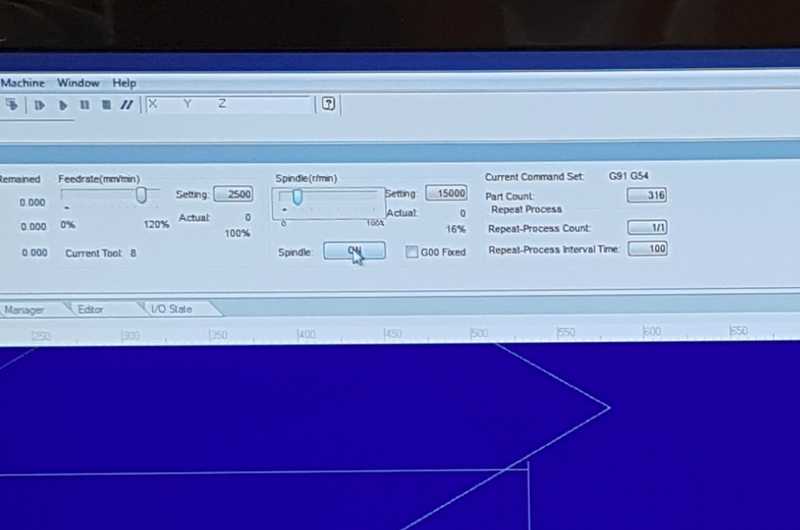
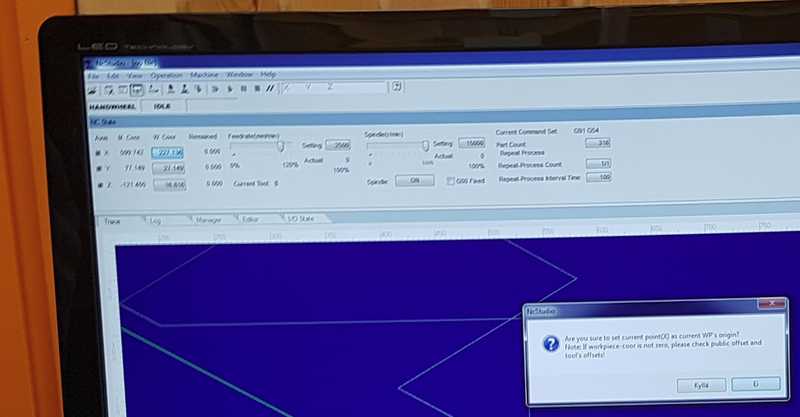
Move the tool to lower left corner of your stock material, where you want to start milling and zero the x and y coordinates. In the NcStudio upper left corner are two sets of coordinates, Machine coordinates and Work coordinates. The Work coordinates are used to set the work zeros. The coordinates are zeroed by pressing the coordinate (and selecting yes or in our NcStudio where this is translated in Finnish 'Kyllä'), you want to be zeroed for the work.
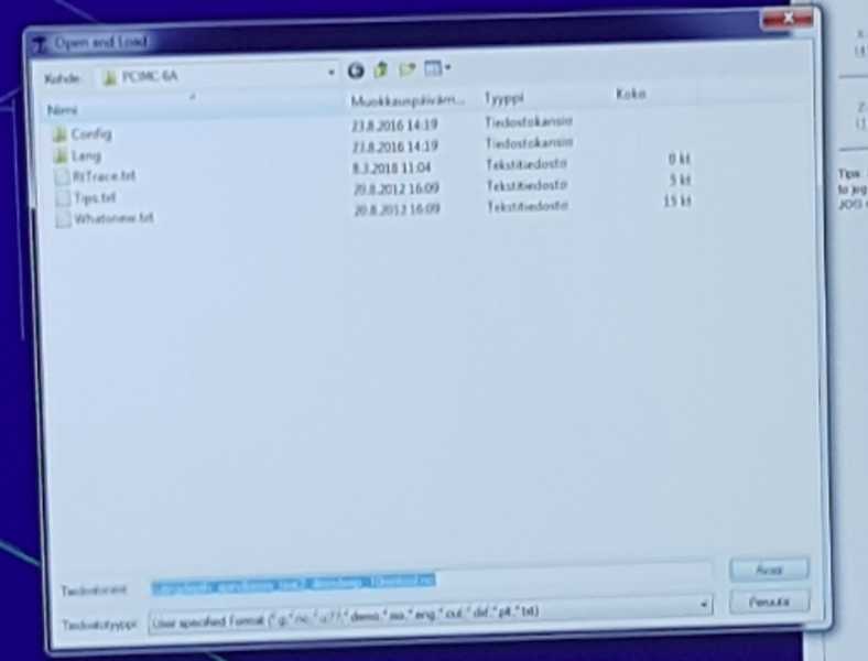
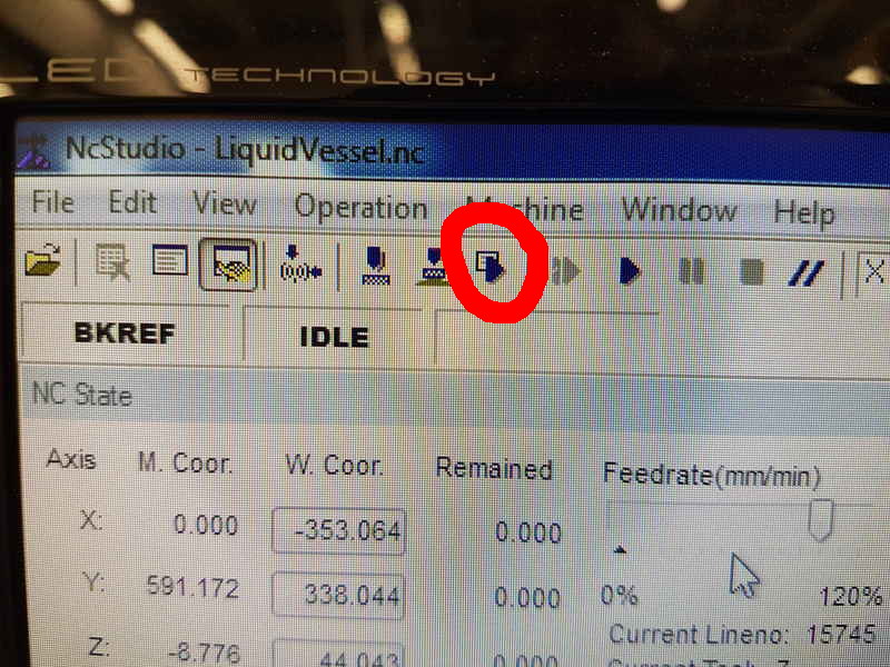
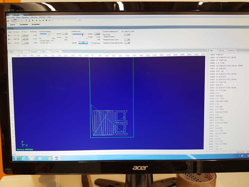
Now you upload your nc-program to the machine and simulate it using your current settings. If there is a old work showing, you can clear the view by selecting the blue constructing area by clicking right button and press clear. In the upper tool bar, there is a play button with white square, which is used to simulate the cut your work.
Simulated work is shown below.
If you can see that there are no problems and the stock is big enough for your work, you can start milling by pressing play button. When the milling job is ready shut down the machine in the reverse order that you switched it on and remove the tabs with carpet knife and the part should be loose. Remove it and remove the stock material and clean the CNC router from dust. You can remove the milling tool also.
Post processing
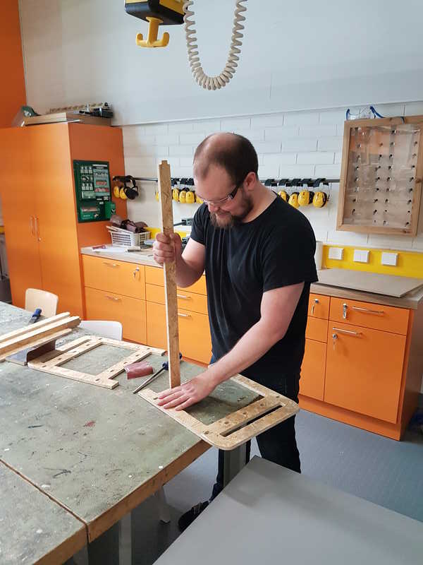
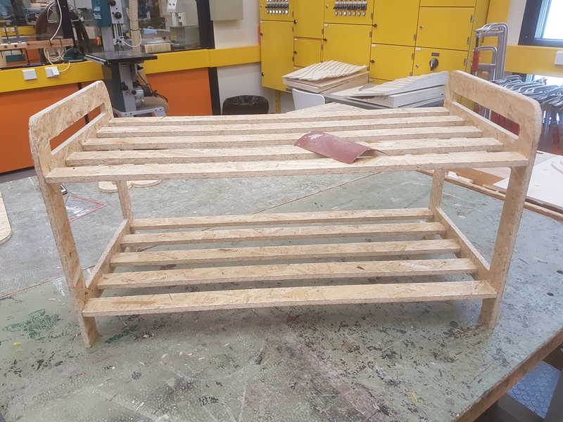
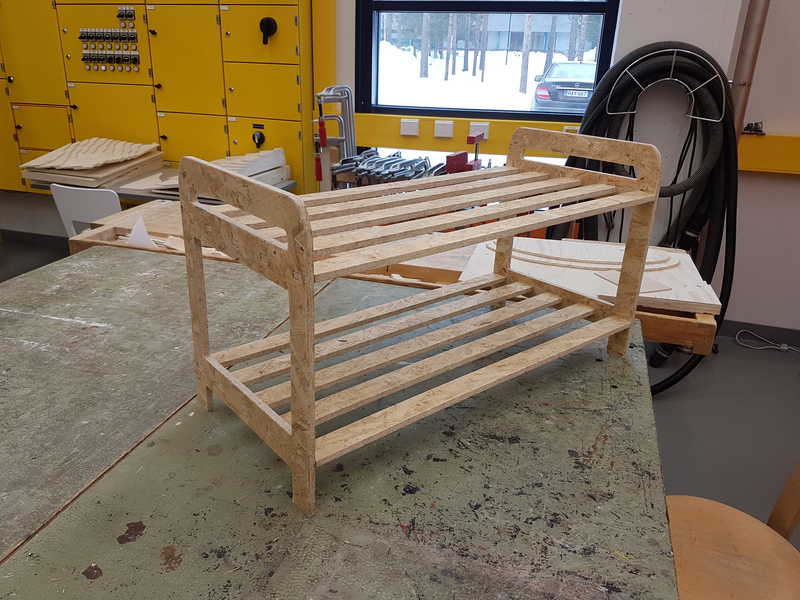
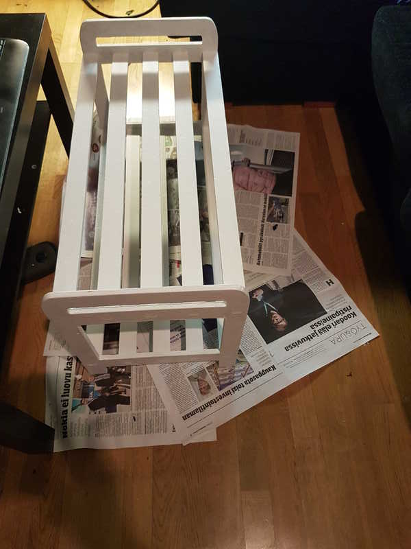
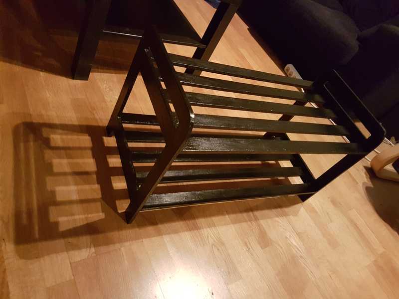
The milled parts take some post processing before I could build the shoe rack. I used belt sander to clean the edges and make a small fillet on all edges except joints. After that I filed all the joints to make them fit. The first ones took about 5 min, but after I learned to see when the joint is ready, it took only about 20 seconds to create a joint. In less than two hours the whole thing was ready. I took the shoe rack home and used wood filler to fill all the holes in the OSB board, because it seemed to loose flakes in considerable pace. I sanded smooth surface and added paint primer. Shoe rack is waiting for the final painting and to be put in use.
Reflection on this weeks assignment
This weeks assignment was very fun and useful. I finally got my shoe rack and it works nicely and the custom design assures that it is perfect fit for my purposes. My global reviewer suggested that I might have overdone the amount of tabs in my design and I agree with him. I used the default value for my shoe rack and in that case it produced too many tabs. Also I would create dog bones for joints. The filing and sanding of joints was mildly irritating even if it didn't take that much time after I did the first one. I would have also used smaller diameter tool so that dog bones would not be so big.
The files used in the assignment are shared below: ComputerControlledMachining.zip Autodesk Inventor and CNC Files for the Computer-Controlled Machining
CNCSTLFiles.zip STL files for the Computer-Controlled Machining