Week 9: Embedded Programming
This week's tasks:
- Group assignment:
- Comparing the performance and development workflows for other architectures
- Link to the Group Assignment Page
- Individual assignment:
- Reading a microcontroller data sheet
- Programming our board to do something
Challenges:
- Reading a 286 pages document, which is not just a story but a difficult concept to grasp is quite challenging and it was not possible for me. I read some introductions from the document. I decided to use and edit a ready code and also use this data sheet as a reference for understanding the parts of the code.
- I first installed Atmel Studio 7 because I wanted to reuse a C code. But I found it a bit challenging for me. So some students suggested Arduino. I read about it and browesed some code samples. And I found Arduino platform simpler to go ahead with.
- Understanding how to match the pins of my sketch with Atiny44 and Arduino was a bit challenging at the first.
- I added a video to this page using iframe, and I wanted to find a way that video plays muted when the page is uploaded. But I couldn't find a solution for it. Any suggestions?
Actually a not brilliant solution was using the video as instagram story, which gives you the option of muting the video and then saving the video and reusing it unmuted :-D
Considerations:
Technology used:
- Atmel Studio 7.0 Software
- Arduino 1.8.5
ATtiny44A
"The high-performance Microchip picoPower 8-bit AVR RISC-based microcontroller combines 4KB ISP flash memory, 256-Byte EEPROM, 256B SRAM, 12 general purpose I/O lines, 32 general purpose working registers, an 8-bit timer/counter with two PWM channels, a 16-bit timer/counter with two PWM channels, internal and external interrupts, an 8-channel 10-bit A/D converter, programmable gain stage (1x, 20x) for 12 differential ADC channel pairs, programmable watchdog timer with internal oscillator, internal calibrated oscillator, and four software selectable power saving modes. The device operates between 1.8-5.5 volts." (reference)
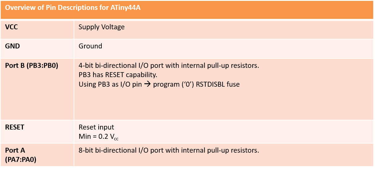
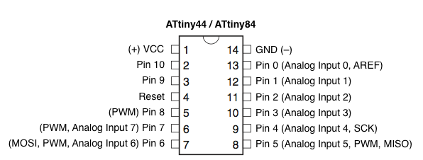
I made this table for myself as a quick access to pin description of ATiny44A.
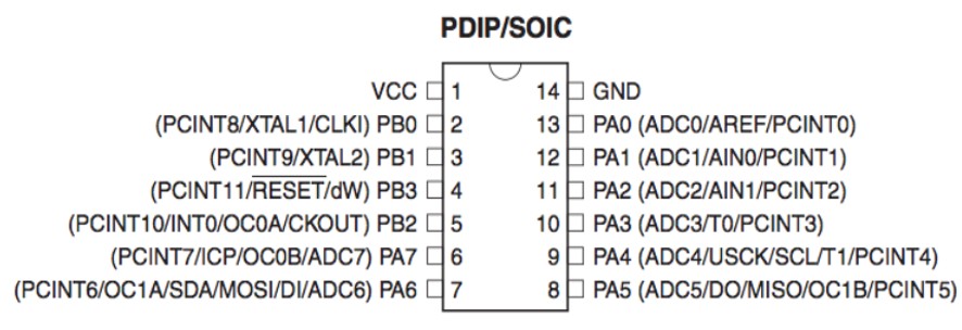
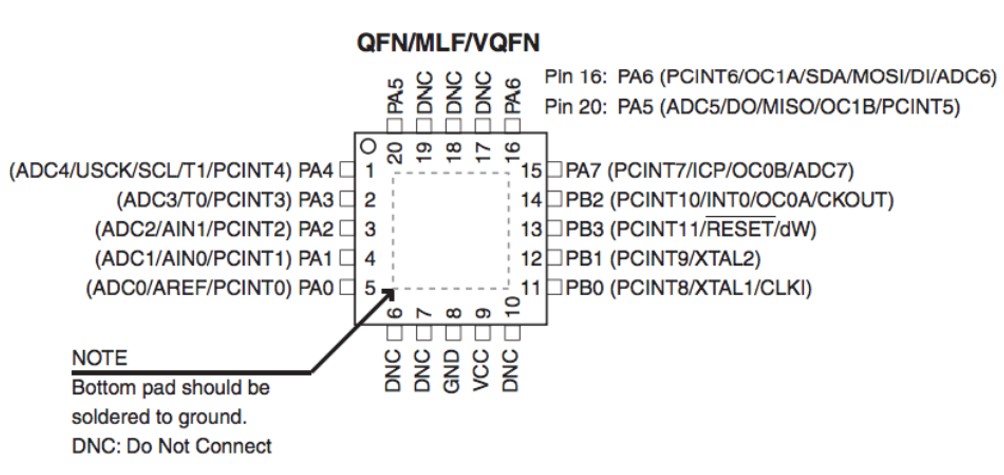
Pinout of ATiny44A. (pictures are screen shots from the data sheet)
Editing a Program
I decided to re-use the code written by Antti and Jani. Their program reads the state of the button connected to I/O pin PA7 to control the state of the LED connected to I/O pin PB2.
/*
* Fabhellobutton.c
*
* Created: 11.3.2016 8:46:20
* Author : anttim
*/
#include <avr/io.h>
int main(void)
{
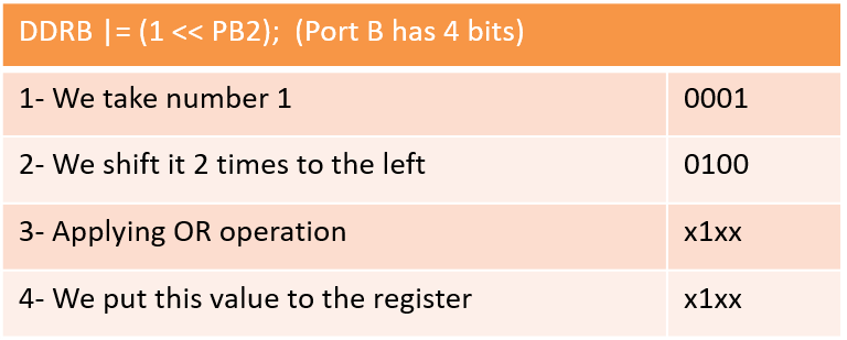
DDRB |= (1 << PB2);
// with OR-operation set bit number 2 in DDRB
register, make it output
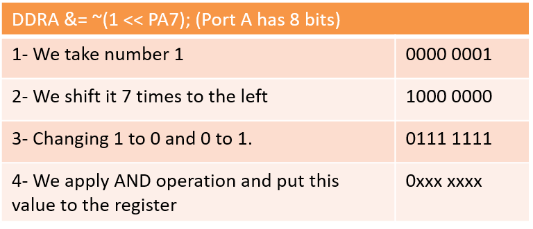
DDRA &= ~(1 << PA7);
// clear bit number 7 in DDRA register, make it input, shift 1
left by seven, 10000000, AND with one's complement 01111111
/* Replace with your application code */
while (1)
{
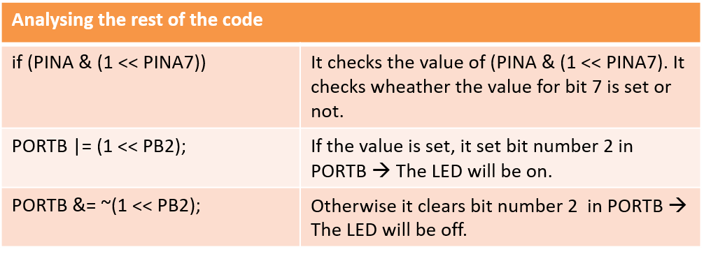
if (PINA & (1 <<
PINA7)){ // with AND-operation check if bit 7
is set
PORTB |= (1
<< PB2); // with OR-operation set bit number
2 in PORTB
} else {
PORTB
&= ~(1 << PB2); // with AND-operation
clear bit number 2 in PORTB
}
}
}
Analyzing the code
First, I tried to understand the elements of the code.#include <avr/io.h>
- "This header file includes the apropriate IO definitions for the device that has been specified by the -mmcu= compiler command-line switch." (reference)
int main(void)
- A function that expects no arguments and returns an integer.
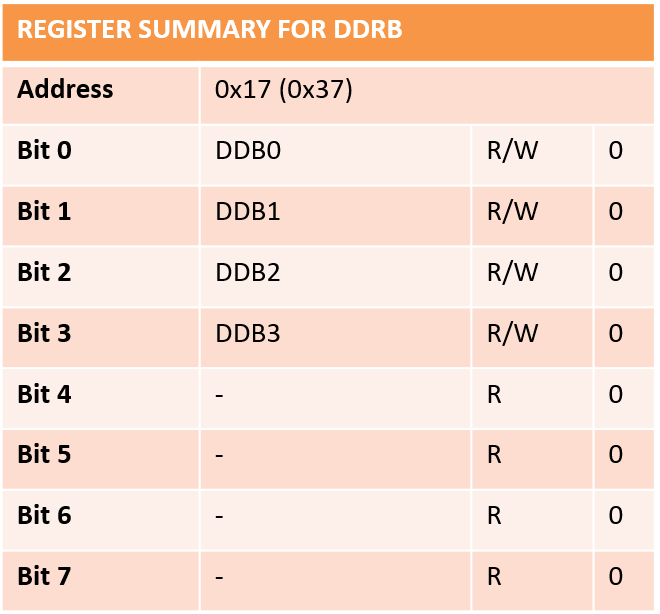
DDRB
By refering to the data sheet and also google serach, I figured out that:- A microcontroller is a small computer that contains CPU, memory and programmable input/output peripherals.
- AVR is a family of microcontrollers manufactured by Atmel.
- In the ATtiny44A, there are 32 general purpose working registers.
- And "DDRB is a bitmap oriented register that controls the Data Direction of each bit on Port B." (reference)
- In this table, by 0 I mean that 0 is the initial value for all the bits.

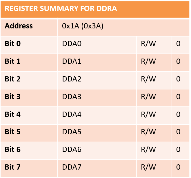
DDRA
- Port A Data Direction Register.
- DDRA is a bitmap oriented register that controls the Data Direction of each bit on Port A.
- In this table, by 0 I mean that 0 is the initial value for all the bits.
- R is for Read. W is for Write.
Bit Operations
&, |, ^, >>, <<, ~
- | bit OR
- & bit AND
- ~ bit NOT
- ^ bit EXLUSIVE OR (XOR)
- << bit LEFT SHIFT
- >> bit RIGHT SHIFT
- PA7 is connected to the button.
- PB2 is connected to the LED.
Arduino
After reading about Arduino, I assumed it as an easy-to-use platform. So I decided to give it a try. So I went through getting started guide, and did as following:
- In order to be able to write programs and also to upload the programs to my borad I had 2 options:
- Using online IDE (The Arduino Software)
- Working offline and using desktop IDE.
- I decide to use online IDE. So I signed up and created an account.
- To use online IDE, I followed these Instructions.
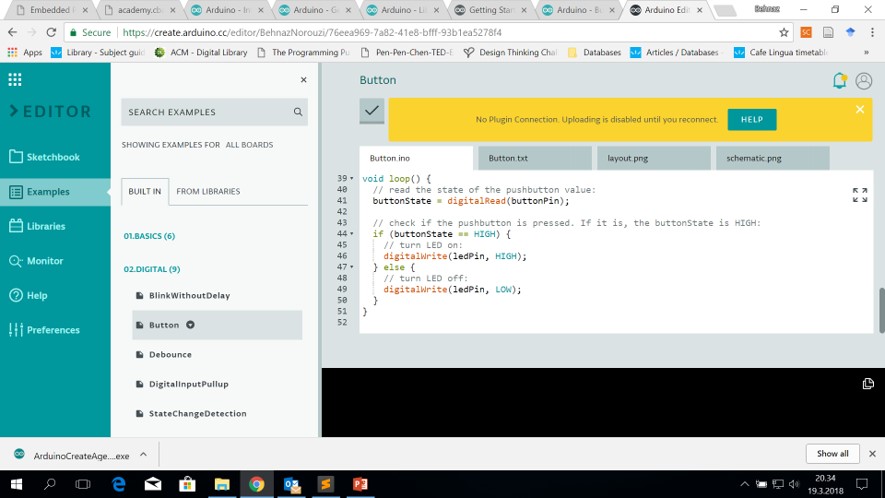
- From Built-In Examples (file > examples > digital > Button), I found the following piece of code that turns on the LED when one press the button:
-
// constants won't change. They're used here to set pin numbers:
const int buttonPin = 2; // the number of the pushbutton pin
const int ledPin = 13; // the number of the LED pin
// variables will change:
int buttonState = 0; // variable for reading the pushbutton status
void setup() {
// initialize the LED pin as an output:
pinMode(ledPin, OUTPUT);
// initialize the pushbutton pin as an input:
pinMode(buttonPin, INPUT);
}
void loop() {
// read the state of the pushbutton value:
buttonState = digitalRead(buttonPin);
// check if the pushbutton is pressed. If it is, the buttonState is HIGH:
if (buttonState == HIGH) {
// turn LED on:
digitalWrite(ledPin, HIGH);
} else {
// turn LED off:
digitalWrite(ledPin, LOW);
}
}
Analyzing the code
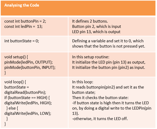
const int buttonPin = 2; const int ledPin = 13;
It defines 2 buttons. Button pin 2, which is input LED pin 13, which is output.int buttonState = 0;
We define a variable and set it to 0, which shows that the button is not pressed yet.void setup() { pinMode(ledPin, OUTPUT); pinMode(buttonPin, INPUT); }
In this setup routine:It initialize the LED pin (pin 13) as output,
It initialize the button pin (pin2) as input.
void loop() {
buttonState = digitalRead(buttonPin);
if (buttonState == HIGH) {
digitalWrite(ledPin, HIGH);
} else {
digitalWrite(ledPin, LOW);
}
}
In this loop:It reads buttonpin(pin2) and set it as the button state;
Then it checks the button state:
-if button state is high then it turns the LED on, by doing a digital write to the LEDPin(pin 13).
-otherwise, it turns the LED off.
Arduino Desktop
For some reasons I decided to use the desktop version. So I downloaded the software from here. And then I installed it. Then following this instruction I:
- installed the ATtiny support by:
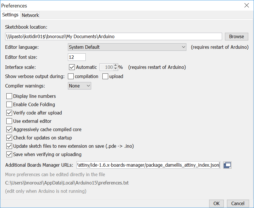
- Opening the preferences dialog in the Arduino software.
- Finding the “Additional Boards Manager URLs” field. And pasting "https://raw.githubusercontent.com/damellis/attiny/ide-1.6.x-boards-manager/package_damellis_attiny_index.json" URL into this field. And hitting OK button to save this updated preference.
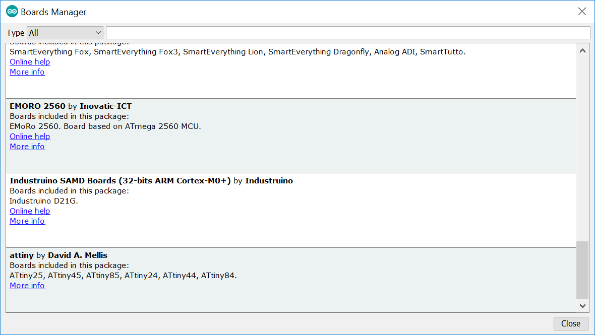
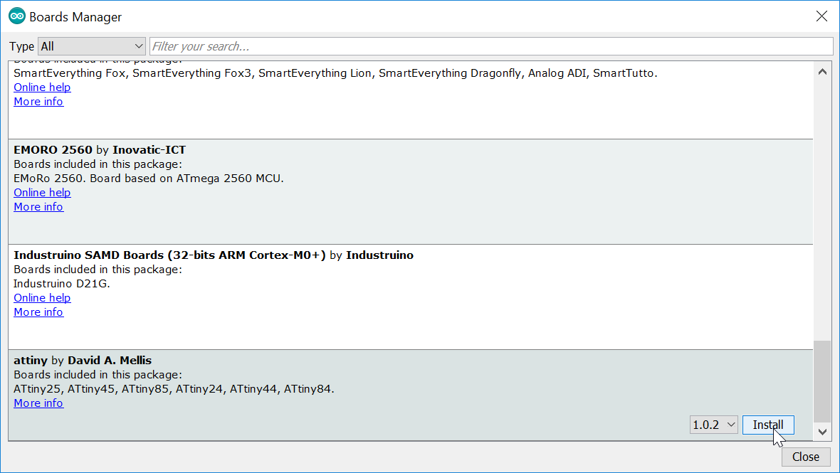
- Opened the boards manager in the Tools > Board > Board Manager. And when I scrolled down, I saw an entry for “ATtiny”.
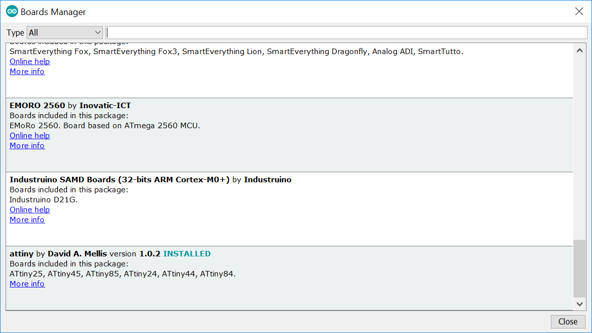
- I clicked on it and the install button appeared. I clicked on it and it got installed.
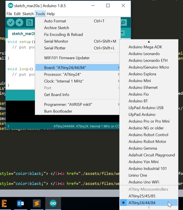
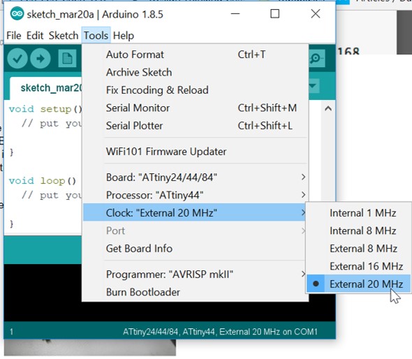
- I went to tools > Board: Now as you see in the picture, 2 entries for ATiny is appeared.
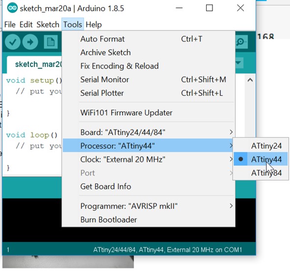
I chose Attiny 24/44/84 entry. - I also set: Tools > Processor > ATiny44
- I also set: Tools > Clock > External 20MHz
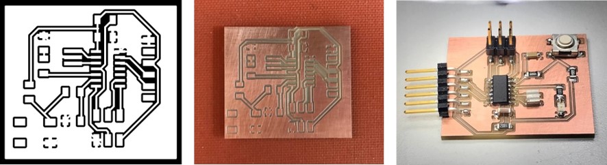
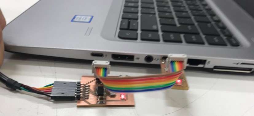
- Connected my programmer to my computer. And in Arduino software from Tools tab I selected USBtinyISP as programmer. I also connected the board that I designed in week7, electronics design. I add some pictures of the board in the following:
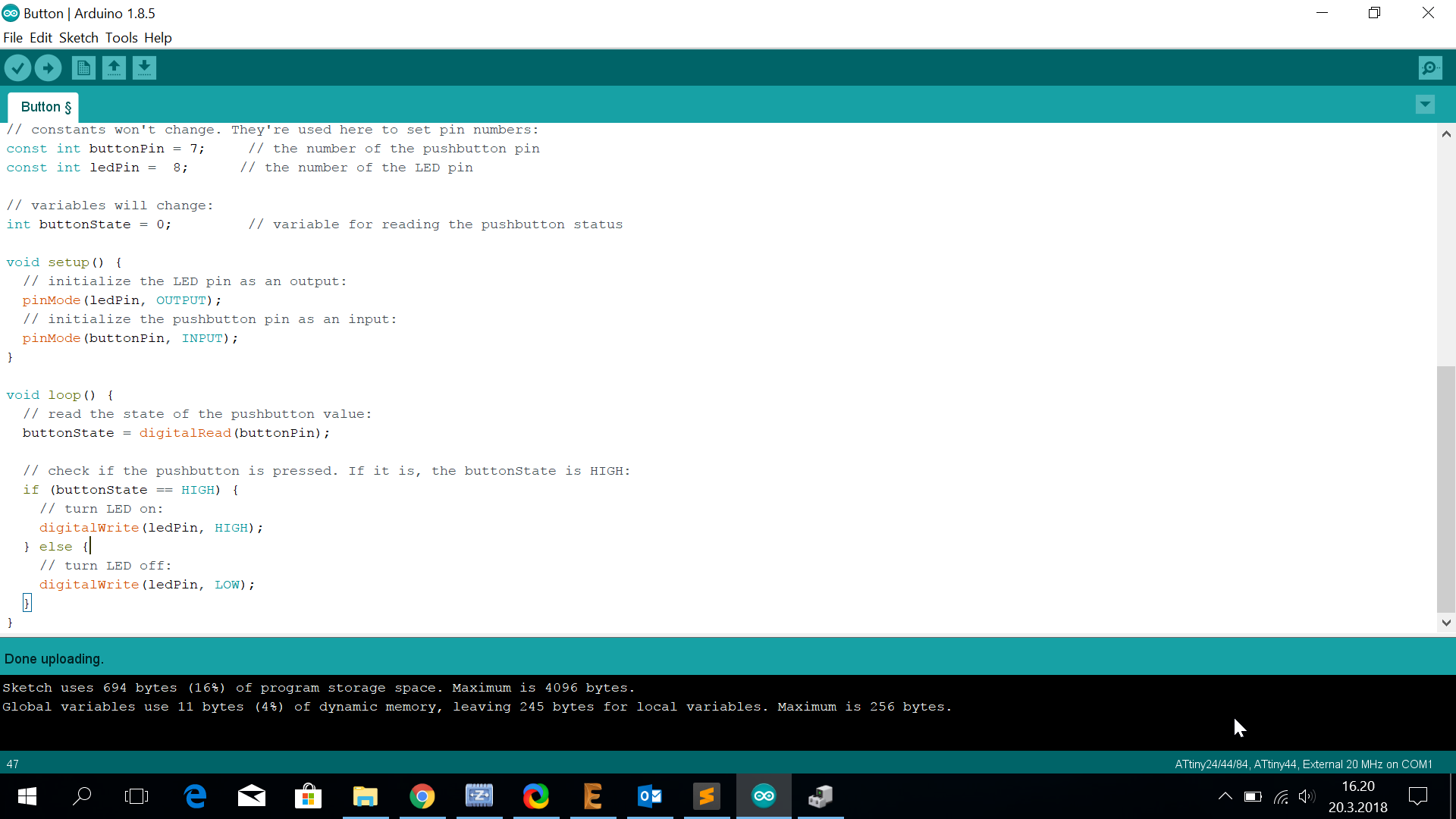
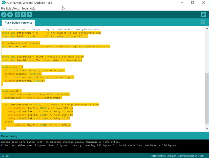
- Edited the code that I analyzed in the previous section as following:
- const int buttonPin = 7; In my schema, PA7 is Pin6 on ATiny44, which is the pin match with Pin7 in Arduino.
button pin = 7 - const int ledPin = 8; In my board Schema, PB2 is Pin5 on ATiny44, which is the pin match with Pin8 in Arduino.
LED pin = 8
¨ - const int buttonPin = 7; In my schema, PA7 is Pin6 on ATiny44, which is the pin match with Pin7 in Arduino.
- Sketch > upload using programmer
Uploading is done successfully. - And here is the final result: by pushing the button I make the LED on/off.
I used iframe tag for uploading my video (.mov). But it did not show the video in my page. I converted the video through an online website to mp4 format. And it worked. And it was better to use mp4 anyways becuase the same video occupied 4mb with .mov and 1mb with .mp4.
- A variable named slowBlink for the duration of 1000 ms of delay.
- A variable named fastBlink for the duration of 25 ms of delay.
- Then when the buttton state is high:
- I turn the LED on and add a delay of 1000 ms.
delay (slowBlink); - And the I turn the LED off and add a delay of 25 ms.
delay (fastBlink);
- I turn the LED on and add a delay of 1000 ms.
The result is shown in the following video:
Original Design Files
ARDUINO file, .ino.rml file for traces of the board
.rml file for outline of the board
Schematic of the board (.sch)
The board (.brd)
ARDUINO file (light pattern), .ino