Designing PCB
This week I finally got around to doing something that relates to my final project. I will make a robot that just moves around on 2 wheels and avoids crashing into things. The natural "input device" for this project is therefore a sonar. I selected HC-SR04 sonar, as we had that in the FabLab Oulu inventory. The sensor has only 4 pins. VCC (Power), Trig (Trigger), Echo (Receive), and GND (Ground).
The basic principle of work for this sensor: (1) Using IO trigger for at least 10us high level signal, (2) The module automatically sends eight 40 kHz and detects if there is a pulse signal back. - (3) IF the signal back, through high level, time of high output IO duration is the time from sending ultrasonic to returning.
The basic stuff about the sonar:
- It measures distance from 2cm to 400 cm
- Accuracy can reach to 3mm.
- Working Voltage: DC 5 V
- Working Current: 15mA
- Working Frequency: 40 kHz
- Trigger Input Signal: 10uS TTL pulse
- Echo Output: Signal Input TTL lever signal and the range in proportion
- The modules includes ultrasonic transmitters, receiver and control circuit.
- Test distance = (high level time×velocity of sound (340M/S) / 2
To get started I studied Neil's hello.hc-sr04 board layout, components photo, and sonar video. Neil had also included sample C code and a makefile to program the board, and Python code for testing/visualizing the sonar readings in the input devices week.
The first thing I did was basically redisign Neil's board in Eagle following my own documentation from week 5 . I used all of the same components as Neil, the only difference was that instead of ATtiny 45, I included ATTiny 44 in my design as I had used it before and also got a little familiar with the datasheet during week 9.
Initially, when trying to prepare my schema, I was pretty lost, wondering what connects where as it was not visible in Neil's files, atleast not for a novice. So I search through the FabAcademy archive and looked for help from previous years student files, from Damaris Cotto and Jessica Wang.
I created a new schema on eagle, and found all of the components on the original design by Neil. This was pretty straight forward picking and choosing as we had done this before on week 7. Here is my original Schema
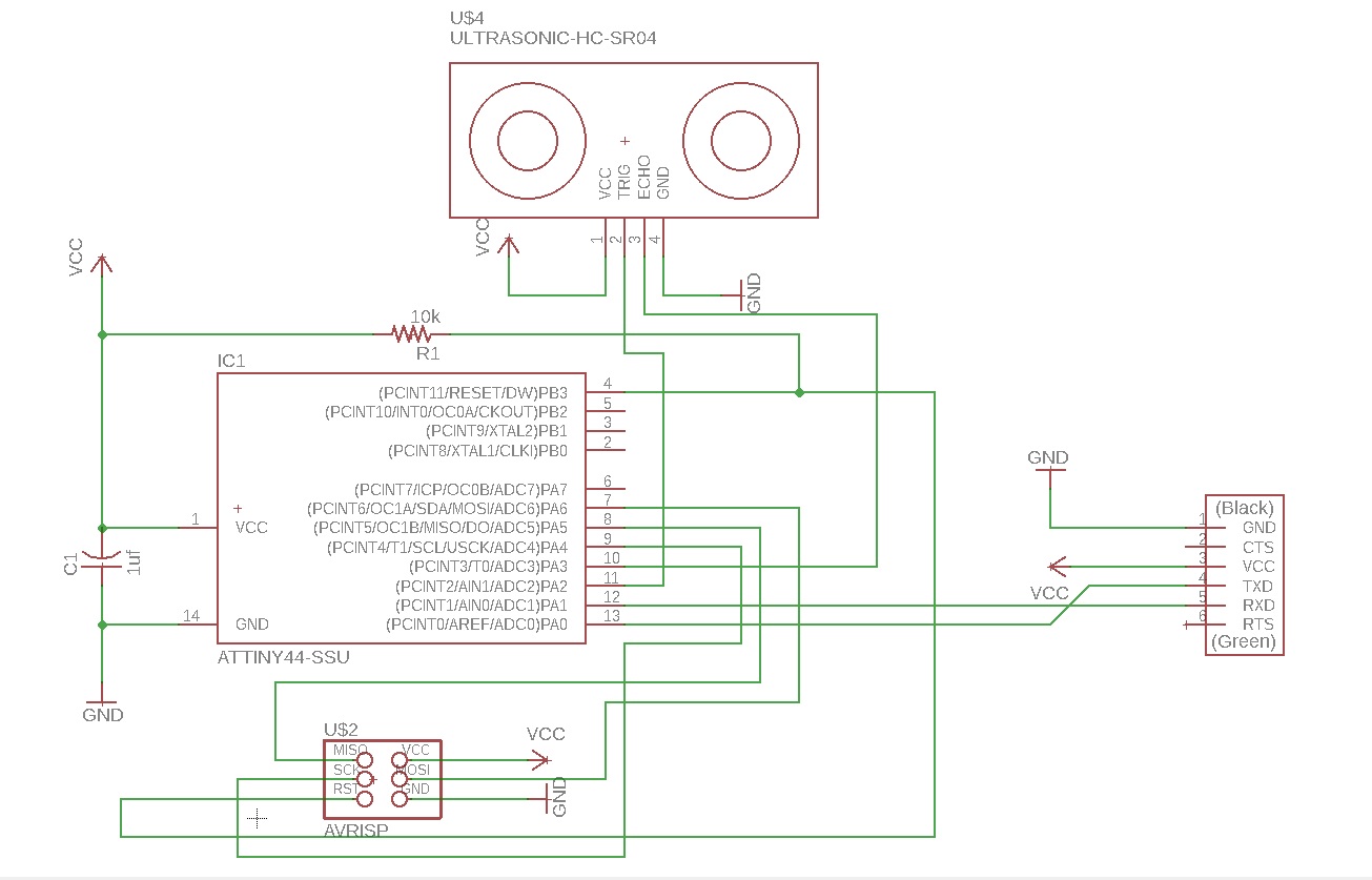
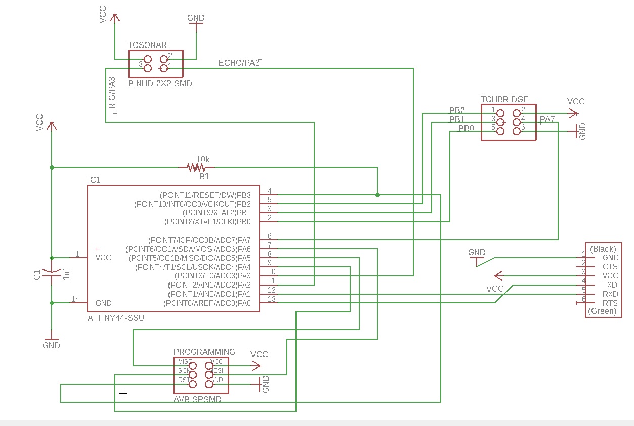
I showed the schema to this week's instructor Juha-Pekka, and he suggested that instead of designing just a sonar board, I turn the board into something that I can use also for my final project.
- This was done by substituting the HC-SR40 in the design by a 4 pin header where where I can attach the sonar later.
- I also included an extra pin header, so that I can use this board for output week and final project where I plan to connect it to a board that has 2 H-bridges for DC motors.
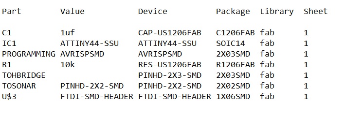
Here is the part list for the board, it includes 1 ATtiny 44, 1 capacitor (1uf), 1 six pin programmin header (avrisp), 1 resistor (10k) 1 2*3 pin header to connect the board later to another board (that hosts the H bridges), 1 2*2 pin header to connect the sonar to this board, and an ftdi header to connect to the computer.
Here is the schema for the board
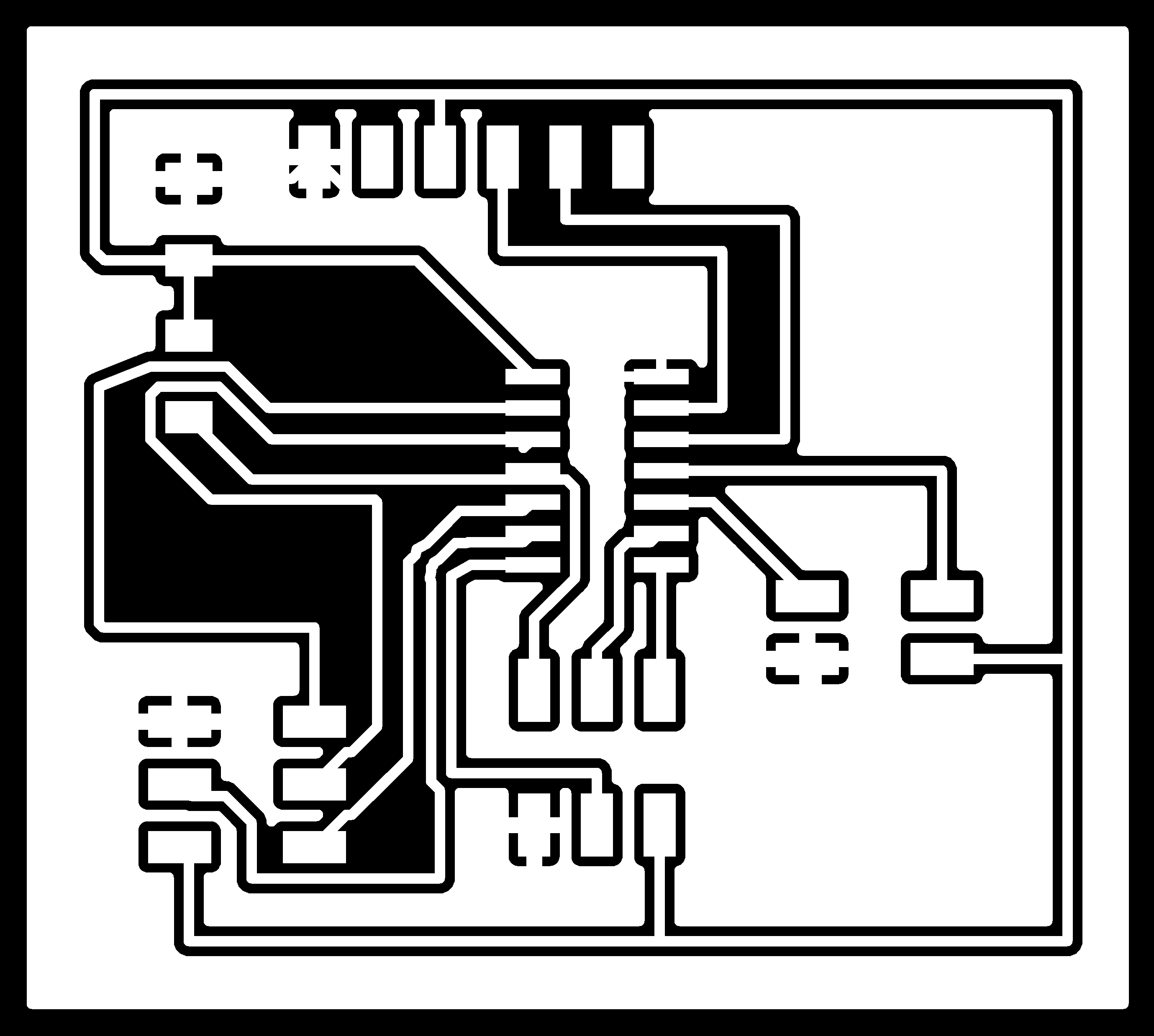
And the board
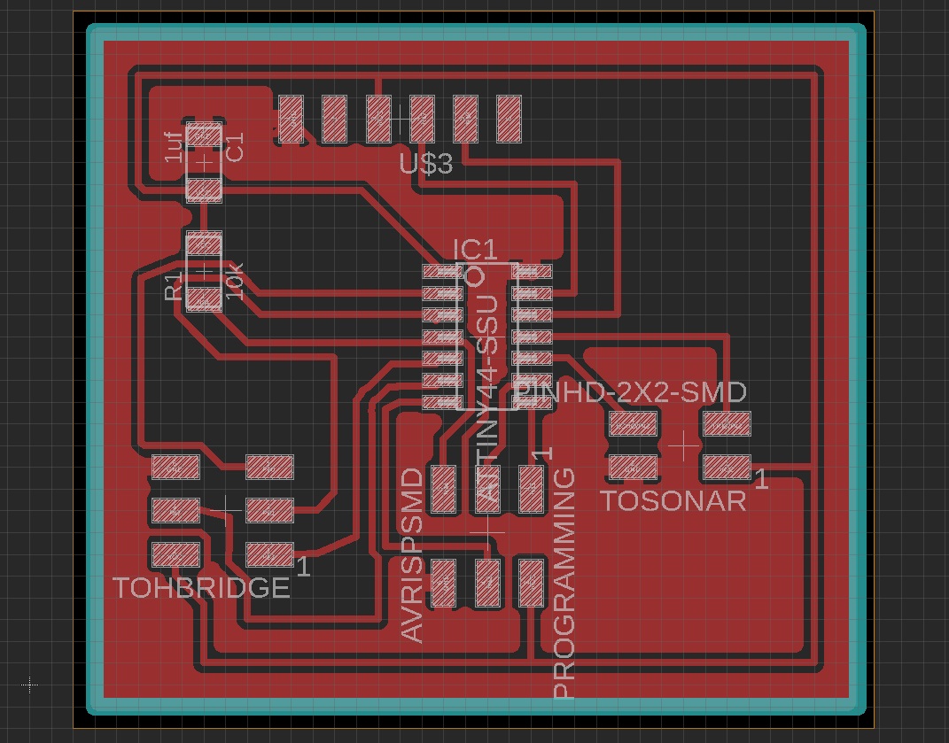
Here are my design files
- FinalProject.sch schema file
- FinalProject.brd design file
- Traces .png file
- Outline .png file
Machining the PCB
When machining the board I used the same workflows already identified on week 5 of Fabacademy.
I went to fabModules website to work on the traces and outline .png files, to include your own milling machine specifications so that the board comes out right.
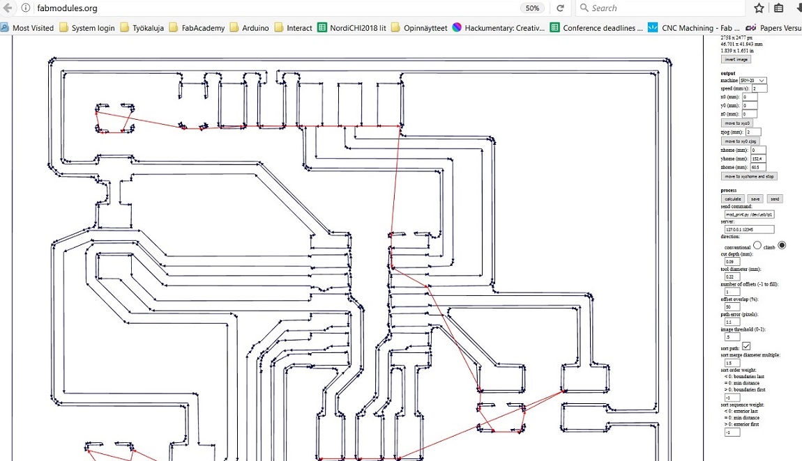
First I imported my traces file,
- I selected the input format to be png.
- I selected the output format to be for Roland Mill (rml), which is the brand of milling machines that we have at FabLab Oulu.
- I specified the I am doing a PCB traces
- I selected what Roland Mill machine I am using - It is SRM-20. When I select this, the FabModules gives me some default settings for the machine.
However, as different machines have different settings, mill heads etc. I then proceeded to modify those settings according to what our local instructor advised us.
- I changed the x,y and z values from 10mm to 0mm.
- I also did some slight modification to the process settings this time, according to what were the last "succesful" settings used by other FabAcademy students. advised I used cut depth 0.09mm and tool diameter 0.22
--> I proceeded to press calculate, and got the following result that shows me milling lines and offsets. I saved it to my computer as a .rml file
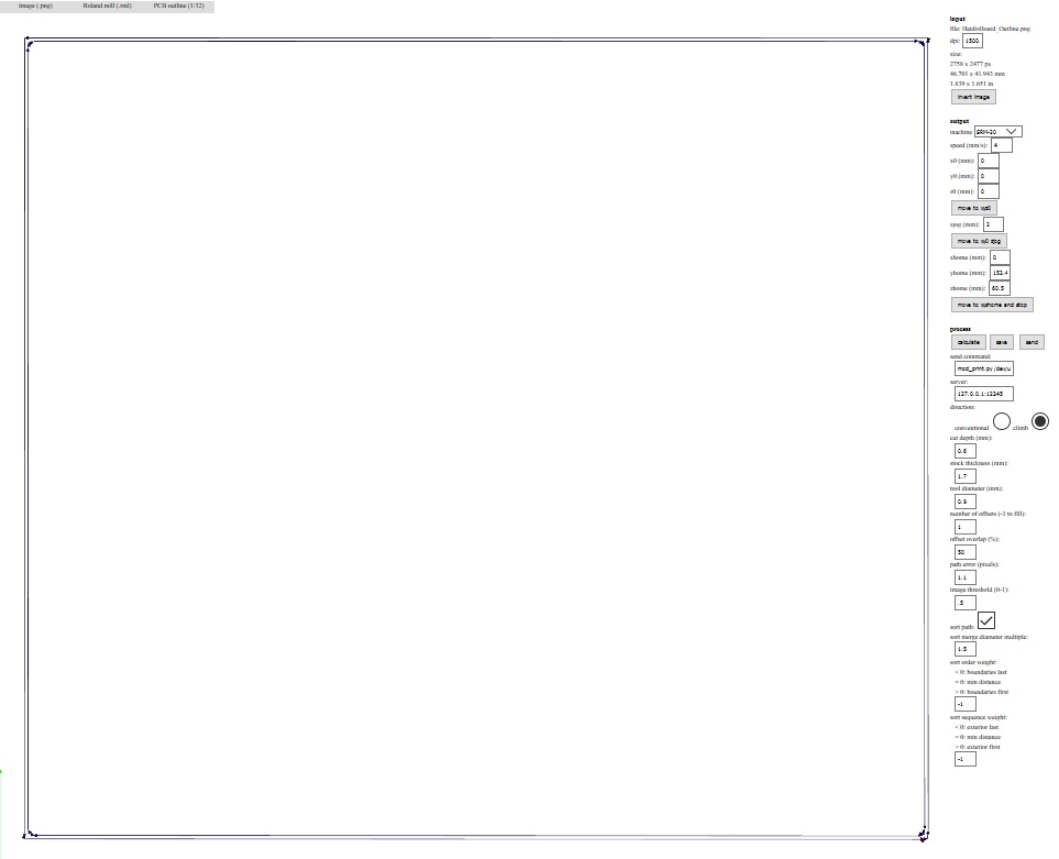
Next it was time to start working on the outline file.
- I again defined that the input file is image (png)
- I then defined that the output format will be Roland mill (rml).
- I specified that this time I am doinf PCB outline.
- I selected the output machine to be the SRM-20 again, and changed x,y and z values from 10mm to 0mm.
- I also did some modification to the process settings: Tool diameter was changed to 0.9mm, cut depth was set to 0.6mm.
--> Pressing calculate gives me a picture that shows me milling lines and offsets. I saved it to my computer as a .rml file
Here are my milling files
- Traces .rml file
- Outline .rml file
I took my rml trace and outline files and headed towards the milling machine and the computer that it is controlled with. Here is the Roland Mill SRM-20 that is used in FabLab Oulu.
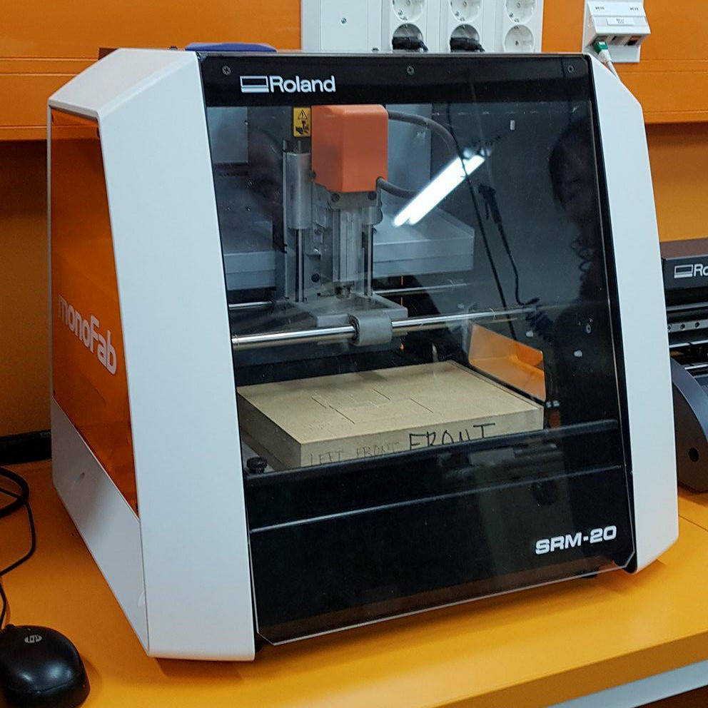
- I removed the inner baseplate from the machine
- I took a fresh copper plate that I will be milling my hello world PCB into, placed double sided tape on it's bottom, and secured it on the baseplate.
- I put the baselate back in the machine and secured it to place, and closed the lid of the machine
- I put in the milling head to the milling machine with the help of the allen key
Next I started to work on the computer.
- I opened up the application that you use to control the machine. the UI of the Roland Mill at FabLab Oulu is called VPanel for SRM-20.
- I used the XY movement keys to move the milling head to the front left corner of the copper plate, and then hit the X/Y button (9) to set the origin.
- I used the Z movement keys to lover the milling head close to the copper plate, then used the allen key, loosen the milling head so that it touches the copper plate, and then tighten it back on. Then used the Z movement keys to lift it a bit from the plate and then hit the Z button to set the Z position of to the base point.
--> Once I got the coordinates fixed, I pressed cut, cleared the cutting queue by pressing "delete all", and uploaded my own traces file there. I press the output button to send my file to the machine to be milled.
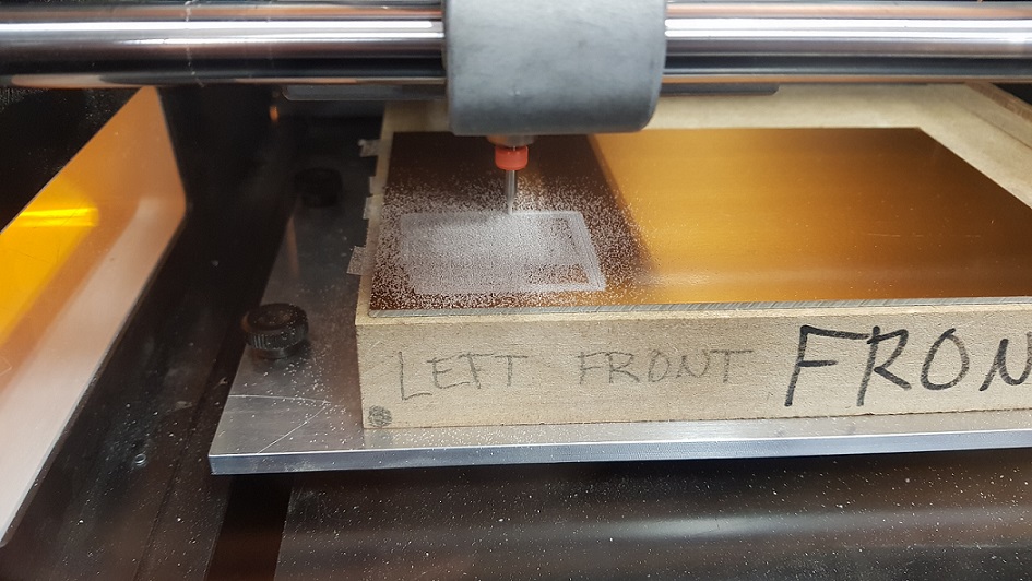
A photo of my traces being milled
- When the traces were milled, I vacuumed the board (without removing it from the machine), and set out to cut the board out of the copper plate.
- First I changed the proper milling head to the machine. We used the flat headed 0.8mm tool. Then I repeated the some of the steps described above for the outline file:
- I used the Z movement tool to lover the milling head close to the copper plate, then used the allen key, loosen the milling head so that it touches the copper plate, and then tighten it back on. Then used the Z movement keys to lift it a bit from the plate and then hit the Z button to set the Z position of to the base point.
--> once I got the coordinates fixed I pressed cut, and a dialoque window opened up. I cleared the cutting queue by pressing "delete all", and uploaded my own outline file there. Next I pressed the output button to my file to the machine to be milled.
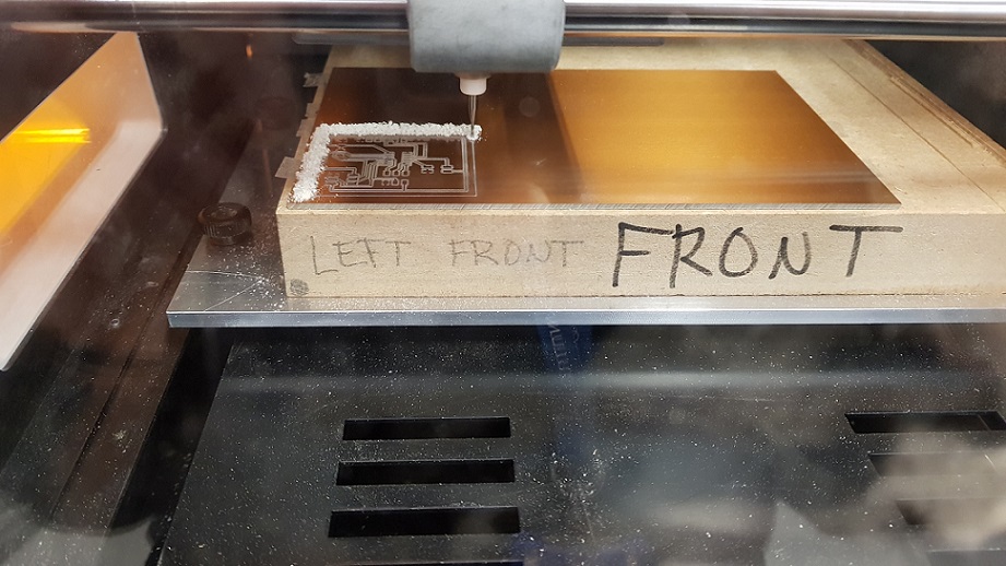
A photo of my outline being milled
Once the outline was cut, I vacuumed the board again, and carefully removed my PCB from the machine. (As there usable copper board still left, I left it attached to the baseplate). After removing the PCB from the machine, I rubbed it with steel wool.
Soldering the PCB
Next it was time to head to the treasure closet to scour all of the components needed for the board. I took the list with me and got
- ATTINY44-SSU
- AVRISPSMD (2*3 pin header for programming)
- PINHD-2X3-SMD (2*3 pin header to connect later to H-Bridge board)
- PINHD-2X2-SMD (2*2 pin header to connect to the sonar)
- FTDI-SMD-HEADER 1X06SMD (ftdi pin header to connect to the computer)
- CAP-US1206FAB (1uf capacitor)
- RES-US1206FAB (10k resistor)
When I started soldering, I felt like the process was taking forever - I heated and heated the pads, and then tried to melt the tin there but the process seemed to be really slow. It took a lot of effort to try and solder the Attiny to place, and the result was not very nice looking. I learned from our instructor Juha-Pekka that I was using a different tin than before - This one did not have lead (or had less of it). I found the stuff with some lead in the cabinet, and the rest of soldering went by much faster. I was explained by Juha-Pekka that when using the unleaded stuff the time to heat it up is longer and one has to use higher temperatures. So the stuff with the lead might be easier for beginners but they both should get the job done. Plus of course, lead is not good for you: According to wikipedia, "Lead-free solders have been increasing in use due to regulatory requirements plus the health and environmental benefits of avoiding lead-based electronic components."
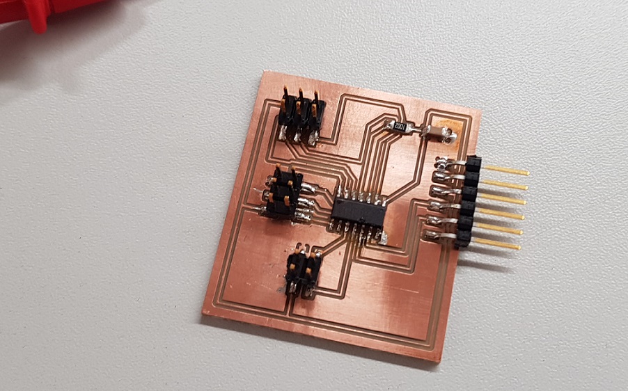
Here is my finished board. I tested it with a multimeter, and all seemed to be in working order.
Programming the PCB
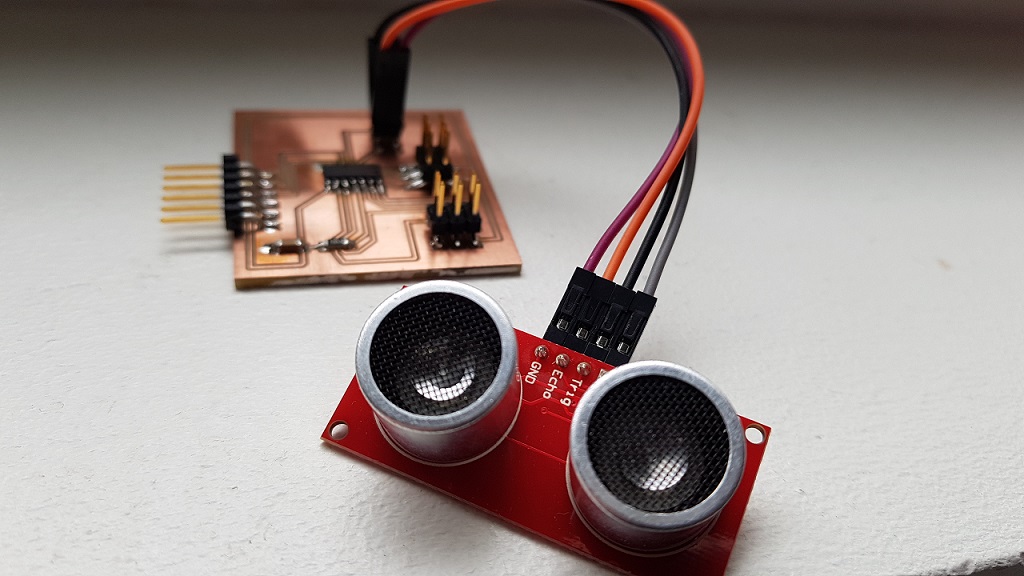
Here is the board with the sonar attached to it with some small wires that I do not know the name of. Apparently they are not very reliable, but atleast they illustrate the point. I conncected my programmer to the sonar board from the AVRISP 2*3 header, and connected it to my computer through the FTDI
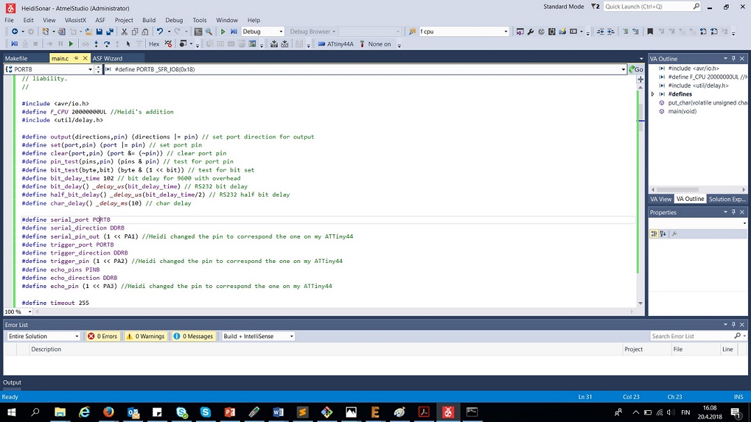
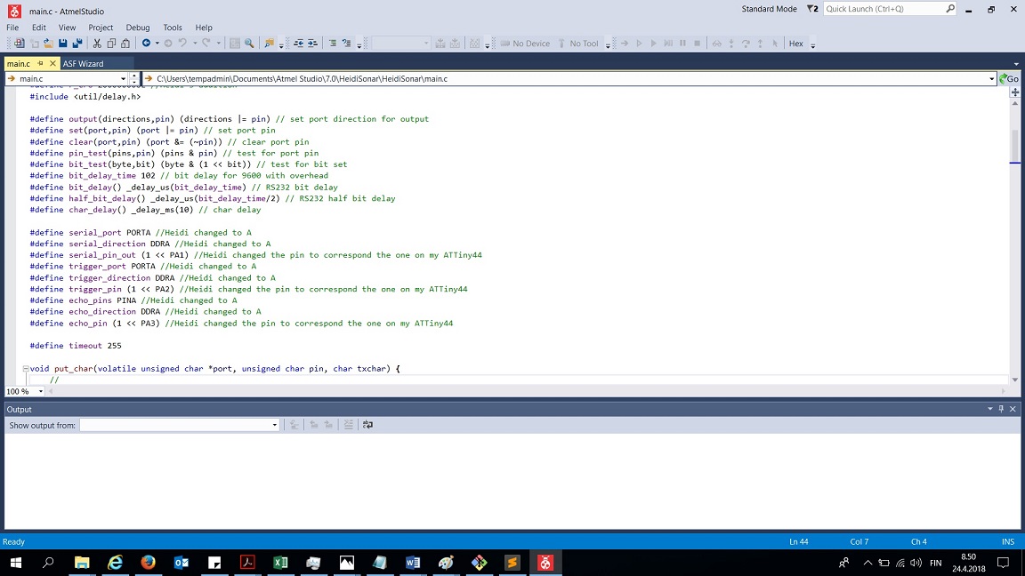
Now it was time to start programming it. I started with Neils HelloHC-SR04 code. As I did not use his schema, and used Attiny 44 instead of AtTiny 45 I had to modify the code.
I started with adding the 20 Mhz (20000000UL) clock and checking the pins, and changing them according to my schema. Whenever I did any changes, I marked it with a comment
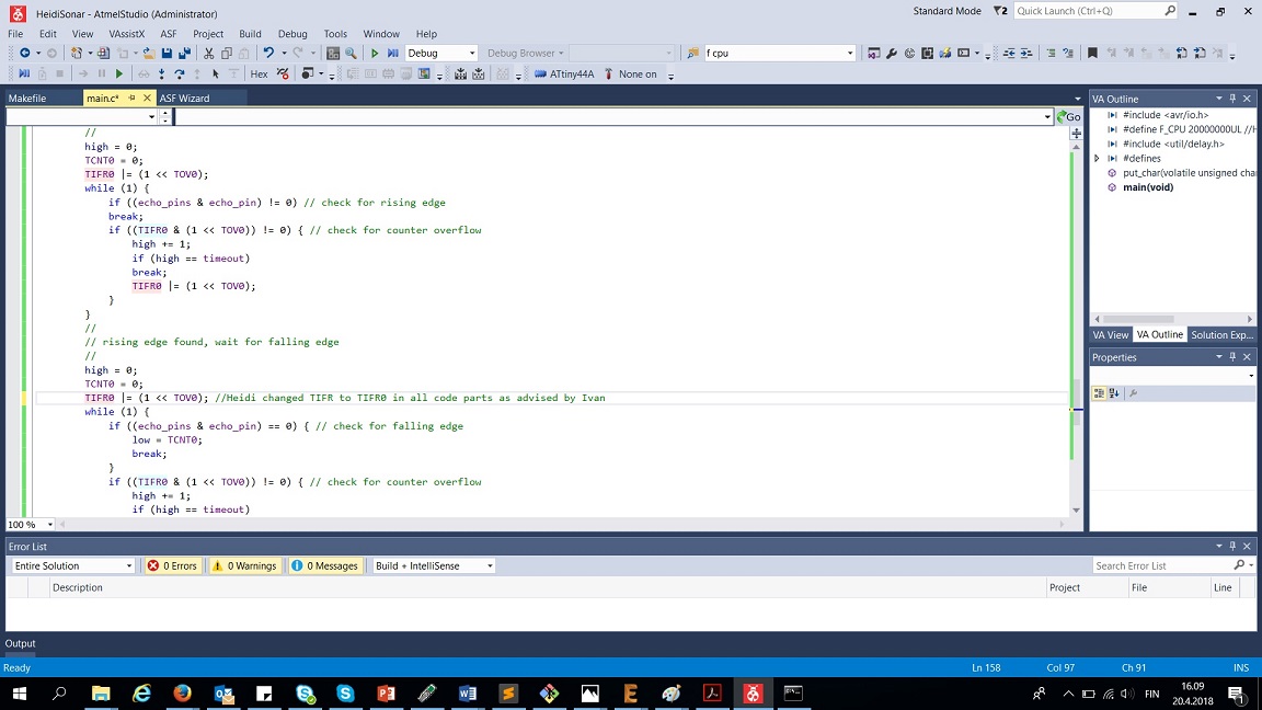
Next I changed the TIFR (Timer Interrupt Flag Register) to TIFR0 in all places in the code as advised by our local instructor Ivan. This was done because I used Attiny instead of ATTiny45
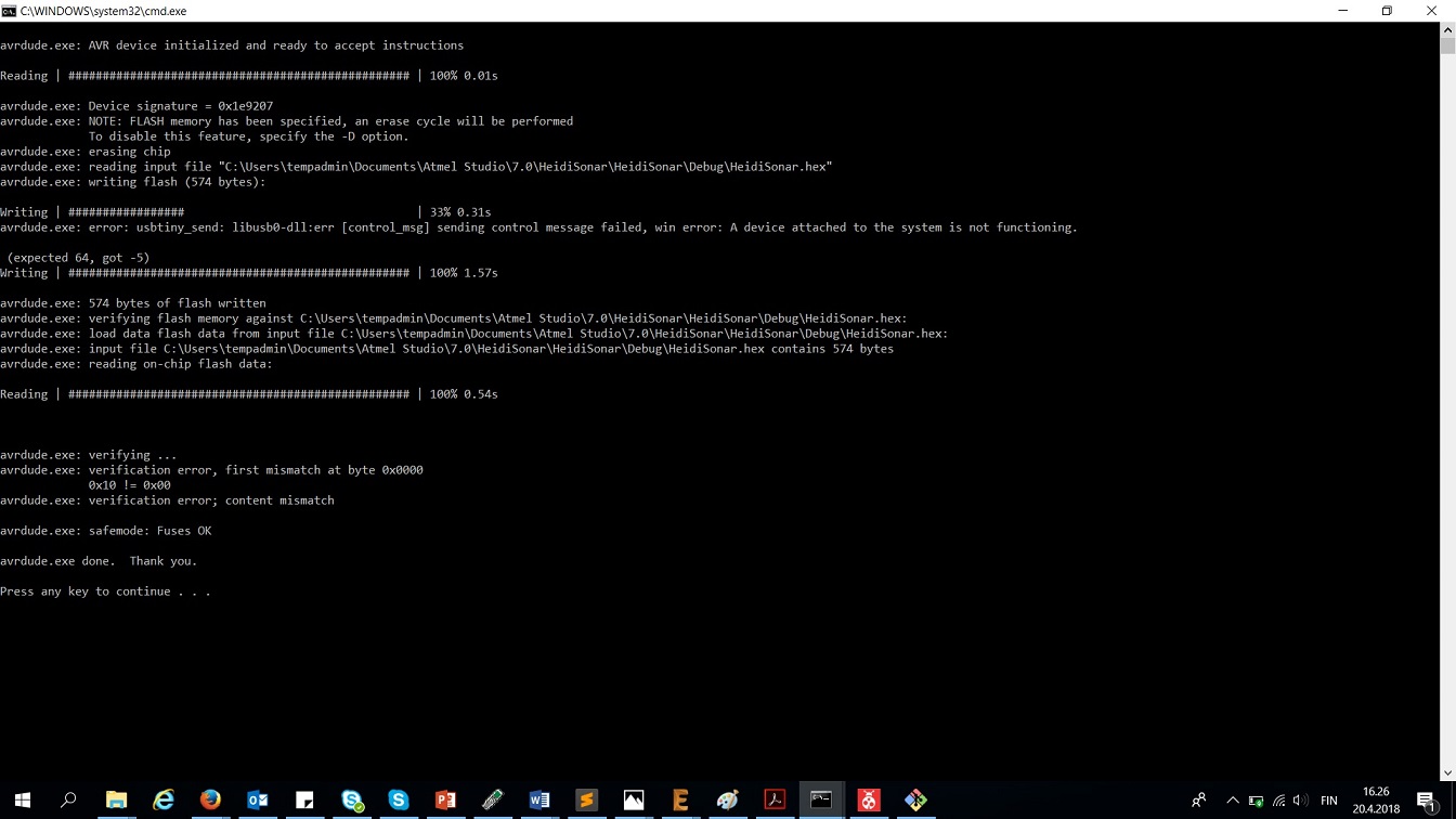
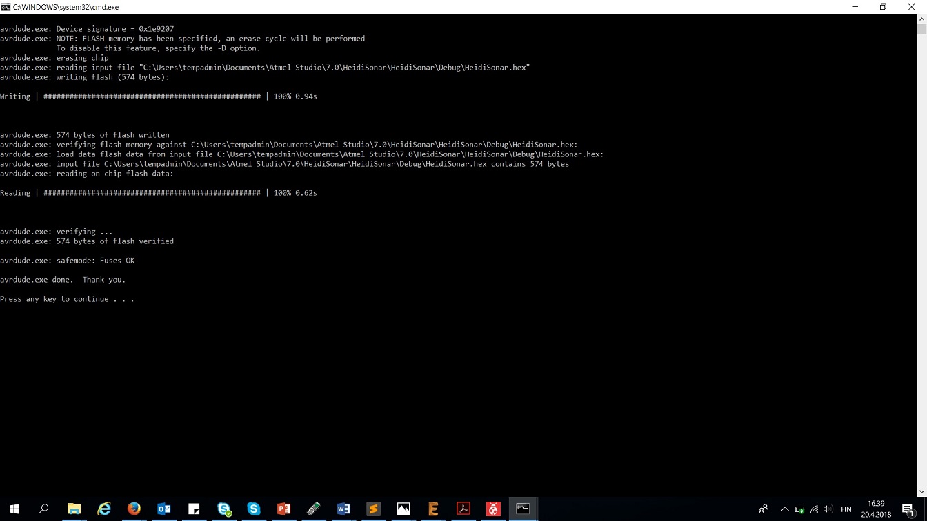
The compile and build went through OK with these changes, but When I ran AVRdude I got some errors.
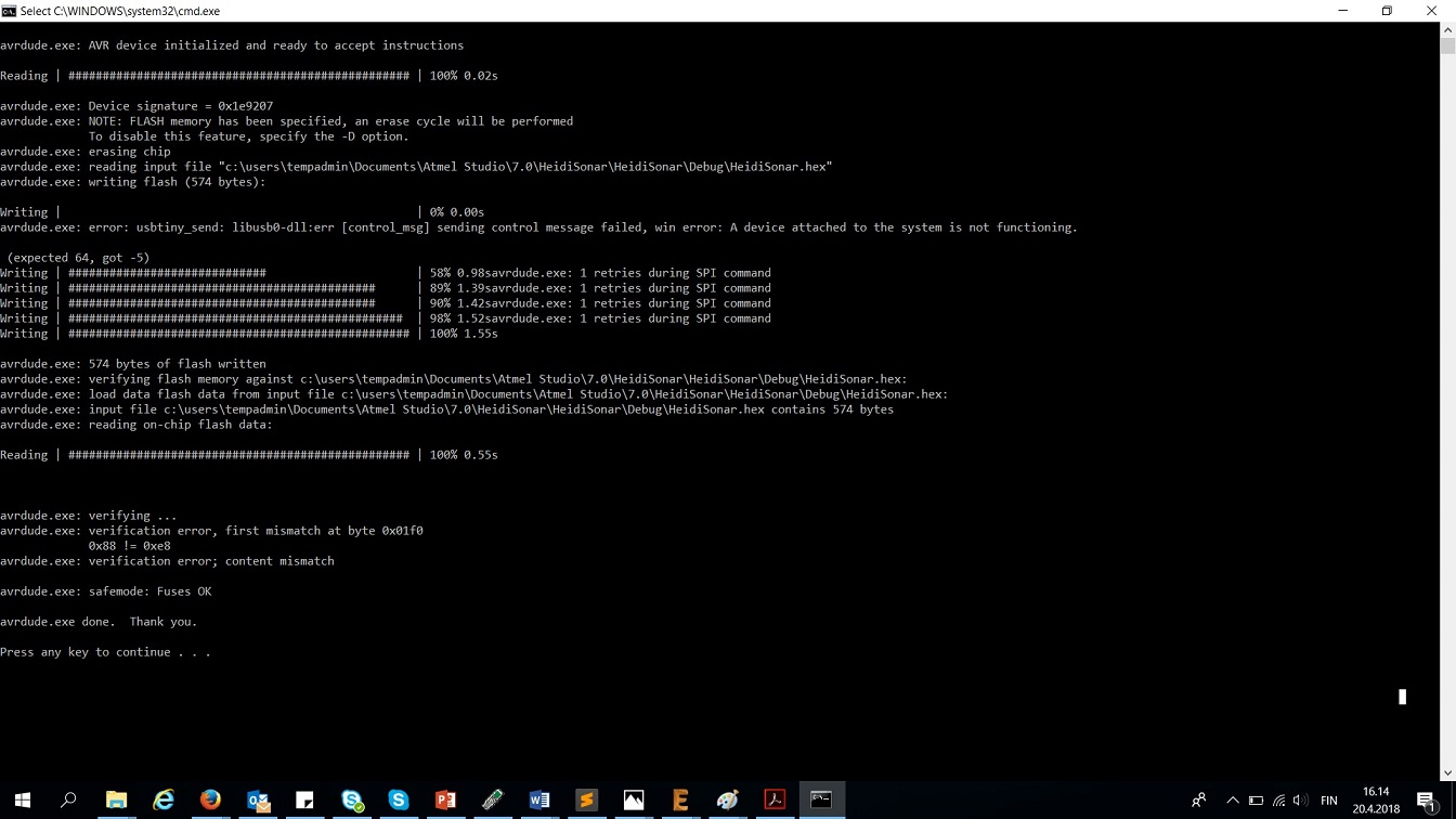
To overcome these, we first checked fuses
.jpg)
Lastly according to Martha's advice, I changed the ports and the trigger directions to correspond to my pins. In neil's original code they were B, in my schema they are A.
After this, the AVRDude was succesful in uploading the program to the board
After this, I installed python 2.7.14 into my computer, to be able to use Neil's python code.
After installing, I went to the folder wehere the python code was located, and tried to run it, but got an error message that I have no serial.
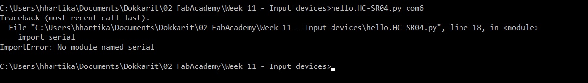
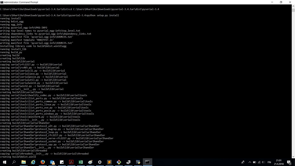
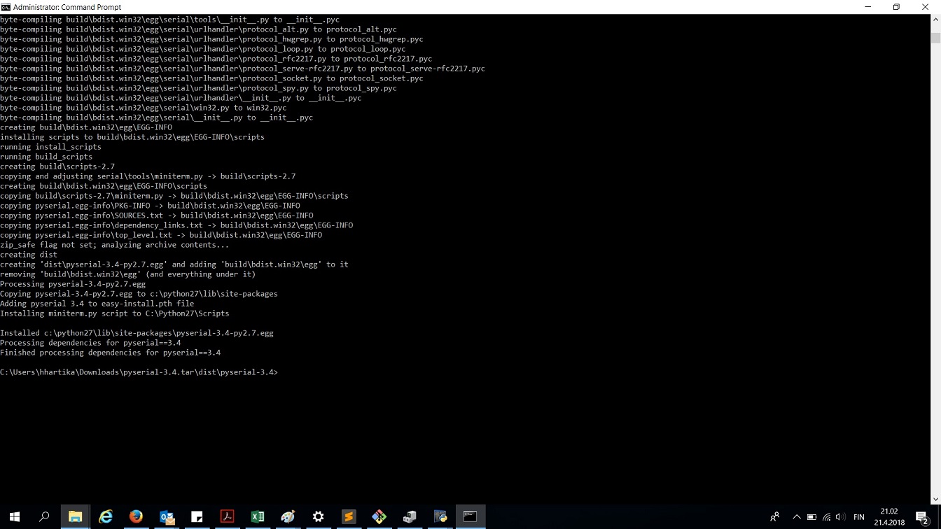
After a bit of Googling, I found out that I have to download and install python serial as well
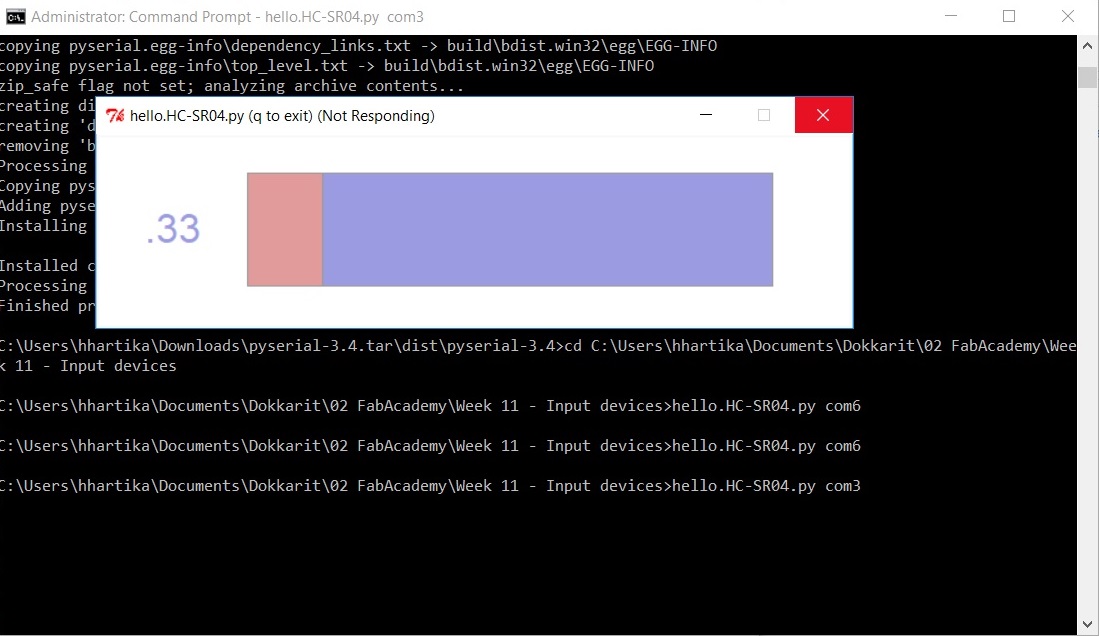
After that, I was able to run the hello sonar program, but it was not actually measuring anything. I tried the device in both Com3 and com6 ports but no difference - The number stayed at 0.33 whatever I did, and every time I ran the program, it stopped responding. I wonder if this is because I still need to do something to my C code. Ivan mentioned something that the clock in the ATtinys is different, and because of this it might not work?
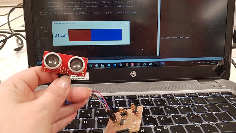
Picking up with the C code a couple of days later, I continued to think about the clock. I heard that Jari from our FabLab had also switched from Attiny 45 to attiny44 in his project, so I might find luck with looking at his page. Sure enough, he had changed the clock to be 8Mhz (8000000UL) instead of the 20Mhz (20000000UL) i had used in my code. I changed this value from my code, and the sonar is working - behold:
Here is my changed C code:
- Sonar for Attiny44 .c code
Problems had and lessons learned
- This week the board design was fairly straight forward, even when I did most of it solo. I learned from my classmates that I should name the lines/wires that connect throuhg pin headers in another board. This makes it much easies for myself to read my schemas.
- I am working with the ATTIny programming through trial and error. The datasheet is massive and as I do not know where to start searching for errors, I have resorted a lot to browsing the fabacademy archives, searching for people who have done something similar and to look at their code. It works.
- As I have to install everything to my work computer through a temp admin account, I had again problems installing python. It installed beautifully (for the tempadmin) and I remebered to add it to path as well. But of course I forgot to add it to the path of my normal user account --> First times I tried to run the python program through the cmd, it did not know what it was.
Copyright © Heidi Hartikainen 2018
Template copyright ©Blackrock Digital LLC 2013-2018

This work is licensed under a Creative Commons Attribution-NonCommercial-ShareAlike 4.0 International License.