Background and motivation
I am currently working as a post-doctoral researcher at the Interact research group at the University of Oulu, in a project that aims to:
- Empower primary school children through technology making and designerly thinking in education, and
- Develop best practices in cooperation with schools for educating children in technology making and designerly thinking.
In the project I will be working with children aged 7 to 14 in the school and at the FabLab, and I envision a final project that will appeal to primary school children (and their teachers) and that can rather easily be replicated with the children either as is, or as a somewhat scaled down version. Something fun that can be modified, hacked, customized by the kids.
As I have never previously worked with electronics, 3D modelling or the likes, I came to FabAcademy to first empower myself - To get familiar with the environment and to find out what I can later on in the project do there with the children.
W1-2: Highflying initial ideas (I can do anything!!)
I spent the first week just tinkering, browsing the previous years FabAcademy projects, thinking about what would be a simple enough project so that children could replicate it.
But from what I have gathered so far, they might be more experienced than me already - Maybe I should be thinking what would be a complicated enough project to keep them interested?!
I had some project ideas in mind already before the first lecture. I was envisioning something that the children could do in groups, and that could be used in class after the project.
simple robot that teaches sequential thinking
- walks, turns, talks etc according to input (What would be the input? Buttons!)
- Could also dance? Flash lights?
- I scrapped this idea since I noticed I would basically be ripping off beebot
A digital classroom pet
- A toy that would teach the children how to take care of a pet.
- A pet mouse that needs a special kind of environment
- Can sense when for example humidity changes and alerts the kids
- Needs playtime, signals that it is unhappy when it has not been played with etc.
- I scrapped this idea since I noticed I would basically be ripping off Tamagothci
Both of these ideas stemmed largely from a small project that was created last summer in a maker day in Sunderland FabLab. I was a part of the project team, and after the maker day we received small funding to develop it further. The project was called AdaBee, a classroom pet that teaches primary school age children coding.
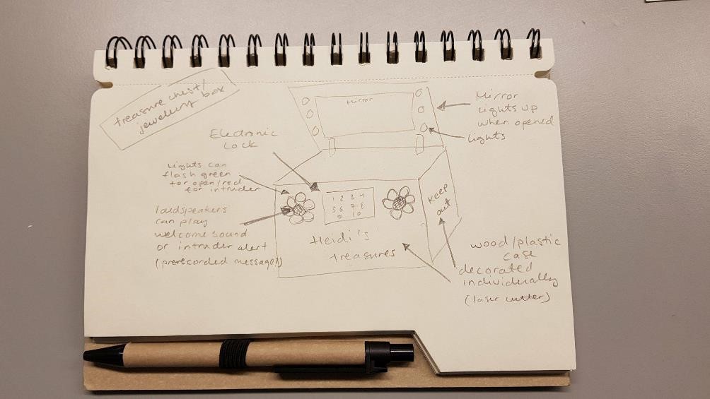
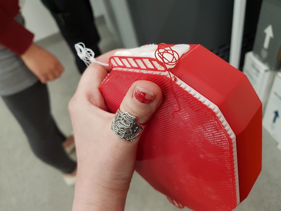
It was back to the drawing board. That is when I came up with (-drumroll please-) An electronic, private, supercool, customizable treasure/jewellery box!!
Who will use it?
- Primary school age children, post doctoral researchers, anyone who wants to keep their treasures
- For girls it can be a jewellery box, for boys a treasure chest. Or vice versa.
What will it look like?
- The casing will be made out of wood or plastic. A small, simple box with a lid that has hinges. The parts could be designed with a 3D modelling program and either lasercut or 3D printed.
- The box can be individually decorated with the laser cutter. 'Heidi's treasures, keep out!' etc.
- The inside of the lid can have a mirror (with a text as well)
What will it do?
1) It will have an electronic lock, so only the owner can open it and all of their treasures and secrets will be secured from prying eyes.
2) When the correct sequence of buttons is pressed, a green light turns on and a welcome sound plays (Or would it be possible it possible to add a pre-recorded message that plays when the right sequence is pressed? 'Welcome owner' etc.). I hope this is feasible in the scope of this project? The problem is that I do not have a background in electronics so I do not know w
--> Plan B: It would be cool if it was possible to unlock it by sound. 'Open sesame' kind of thing?
3) It will light up when you open it, so you can admire your treasures
4) It will react if someone is trying to break into it. If wrong sequence of buttons is pressed, it will light warning lights and make a sound
--> Plan B: If possible to record voice, could add 'intruder alert'? 'Do not touch my stuff' etc. It could also start shaking? Or even run away?
Check out more from my week 1 documentation
W3-4: Getting too ambitious (..and bumming myself out)
This week - after discussing with the colleaques in the "digital empowerment of children" - project, we scrapped the initial treasure chest idea, and selected one of the rougher ideas I had: Building a digital classroom pet. It was considered a more challenging and stimulating project to carry out with the children.
I also ideated a lot of tasks that the children could carry out during the project, including for example:
- Art class: taking pictures of their favourite toys and their pets
- Finnish class: writing an essay about what their ideal digital pet would be, what it would look like, what could it do
- Biology: writing an essay about what is important when taking care of a pet
- Art class: Drawing a first version of the pet
- Math: Learning to use the 3D modelling software
- Art class: 3D model and print the pet
- Math class: Learning to use microchips and inserting block code
- Math: Programming the basic functionality of the pet
- etc etc.: Proceeding to assemble the toys, making presentations, showing them off to others
--------------------------------
Coming up with a final project idea is a bit challenging, as I do not know what I will learn to do during FabAcademy yet. How will my electronics development skills develop? Will I be able to 3D design a not so crappy version of a digital pet? Ideas are brewing though
A digital pet:
- Model after an actual animal, or perhaps a robot
- Outer shell designed with fusion - Either a press-fit kit, or 3D print.
Inside a circuit board, that can do.... What?
- Makes a sonud when it is moved?
- Flashes lights when it hears sounds?
- Flashes colours to music?
- Responds to temperature? Makes sounds when it is too cold?
Todo: Get some inspiration from last years fabacademy projects. Some that were already tipped to me:
- Ola's final project (Sensitive dog)
-May's final project (KidoFab)
-Gabe's final project (empathy elephant)
To think about
- Will this be doable with children aged 7? 10? 13?
- Using tinkercad to build the shell?
- Using ready boards and block coding (raspberry pi, Adafuit circuit playground)
- Would a robot be a simpler design task?
Doodling in class...
W5-9: Long hiatus
I have had a long hiatus, during which I have had a lot of teaching and project stuff/paper writing. I have only been able to put the minimum amount of effort into my FabAcademy which is frustrating. During these weeks I have however kickstarted the project with the children, discussed about what the teachers are interested in, and had many discussions with other fablabbers about my project.
W10: Discussing the project with Neil
In this week's class I had a good discussion with Neil about my project. Below is a video of the lecture video, my part starts at the 10 minute mark.
Fab-20180404B_Review09 molding and casting from Academany on Vimeo.
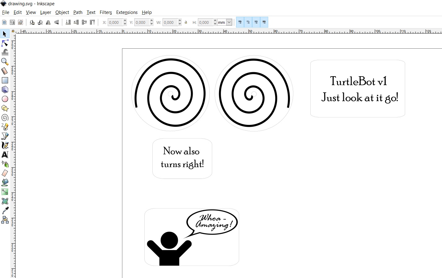
I introduced myself to Neil and talked a bit about my background. Then I presented my initial ideas - the threasure chest and the digital pet, and explained that I had thought it a bit ambitious, and I should scale down. Neil was reassuring me tha it is not at all too ambitious to build some small robot, and introduced me to his mentor Seymor Papert and the logo turtle.
Neil explained to me that Seymour believed that children learn as scientists, but we teach it out of them by experimenting - He wanted to expand how children could experiment, and when he came to MIT, he wanted kids to use computers. This which was considered quite crazy at the time as the computers were only used by corporations but he did it anyways. A famous experimet was the turtle, where kids used the minicomputer at MIT (which at that time filled a room) to control a small turtle robot. Our of these experiments later grew the logo programming language, lego mindstorms etc.
Later in life when FabLabs were growing, Seymour had talked with Neil again and explained that he did not want children to just control the turtles, he wanted them to make the turtles. Neil suggested that it might be a nice idea to follow in his footsteps - Do turtles with the kids, that we program to do simple things like go forward and turn. A few controls, a couple of motors and a statemachine.
Learning more about Neil's connection with Seymour Papert was a really nice surprise. I had just done a literature review about children and making during which I had leaned about Papert, his experiments with children and the idea of contructionist learning, which I found really interesting. Neil talked about this so enthusiastically that I got really inspired. As Neil said, not all kids maybe can do this separately, but it would be a great group project with a really rich history - and it would tie together nicely with the current state of the class.
I did what Neil suggested and this week:
- Read about midstorm
- read about logo
- read about the turtle
--------------------------------
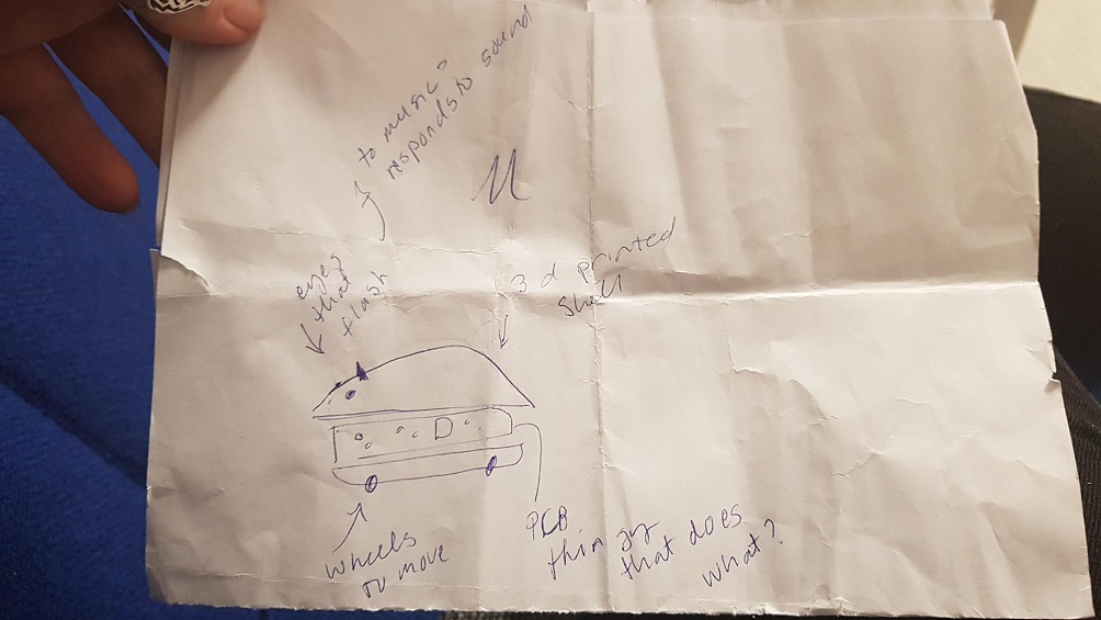
I also though a lot about what kind of a turtle I would make as a prototype!
Built low to the ground
- Flat base shaped like a turtle
- Laser cut out of wood?
Transparent shell shaped like a turtle’s shell attached to the base
- Cast out of plastic, 3D printed, or a laser cut press fit?
- Need to think about how to attach to the base
Wheels underneath to allow for movement (in circular patterns?)
- wheels in the front with motors attached
- 3D print or cast omniwheels for the back?
Power train capable of a very small turning radius
Electronics that are put inside the shell/attached to the base
- Input: Turns on from a button in the base
--> Output: starts moving in a circular pattern (OR JUST MOVES FORWARD)
--> (Output: Green LEDs inside the shell light up when turtle is turned on)
Input: sensors which aid in avoiding obstacles (Bump sensor detects when you hit a wall? ultrasound sensor/Sonar that senses how far you are from an obstacle?)
--> Output: Changes direction (OR JUST STOPS WHEN FACING A WALL)
--> (Output: red LEDs inside the shell light up when the turtle hits wall)
--> Output: Could give audio feedback with bell when turning?
Basically acts like the Roomba vacuum robot, without cleaning anything. Apparently they are common projects for robotics hobbyists. Some of them have colouring pens attached so they can make drawings like the Valiant turtle.
W11: Building final project board and input device
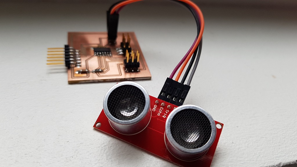
This week I built the my final project board and included an input device in it. The input device for a wall avoiding robot was a sonar. I selected HC-SR04 sonar, as we had that in the FabLab Oulu inventory. All the details can be found on Week 11 documentation, here is a shortened version.
Summary
The sensor has only 4 pins. VCC (Power), Trig (Trigger), Echo (Receive), and GND (Ground). The basic principle of work for this sensor: (1) Using IO trigger for at least 10us high level signal, (2) The Module automatically sends eight 40 kHz and detects if there is a pulse signal back. - (3) IF the signal back, through high level, time of high output IO duration is the time from sending ultrasonic to returning.
The basic stuff about the sonar (from the datasheet):
- It measures distance from 2cm to 400 cm
- Accuracy can reach to 3mm.
- Working Voltage: DC 5V
- Working Current: 15mA
- Working Frequency: 40 kHz
- Trigger Input Signal: 10uS TTL pulse
- Echo Output: Signal Input TTL lever signal and the range in proportion
- The modules includes ultrasonic transmitters, receiver and control circuit.
- Test distance = (high level time×velocity of sound (340M/S) / 2
I studied Neil's hello.hc-sr04 board layout, components photo, and sonar video from the instructions in the input devices week. I also read the introduction to HC-SR04 from Howtomechantronics, which was very simple and informative.
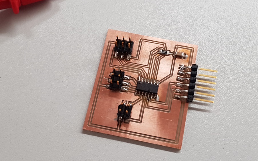
Then I redisigned Neil's board in Eagle. The only difference was that instead of ATtiny 45, I included ATTiny 44 in my design as I had used it before and also got a little familiar with the datasheet during week 9. For the process, I followed my own documentation from electronics production week.
At first when trying to prepare my schema, I was pretty lost, wondering what connects where, as it was not visible in Neil's files, atleast not for a novice. I searched through the FabAcademy archive and looked for help from previous years student, finding good advice from Damaris Cotto and Jessica Wang.
After I was done with the design, our local instructor for this week, Juha-Pekka suggested that instead of designing just a sonar board, I turn this into something that I can use for my final project. This was done by substituting the HC-SR40 in the design by a 4 pin header where where I can attach the sonar later. I also included an extra pin header, so that I can use this board for output week and the final project.
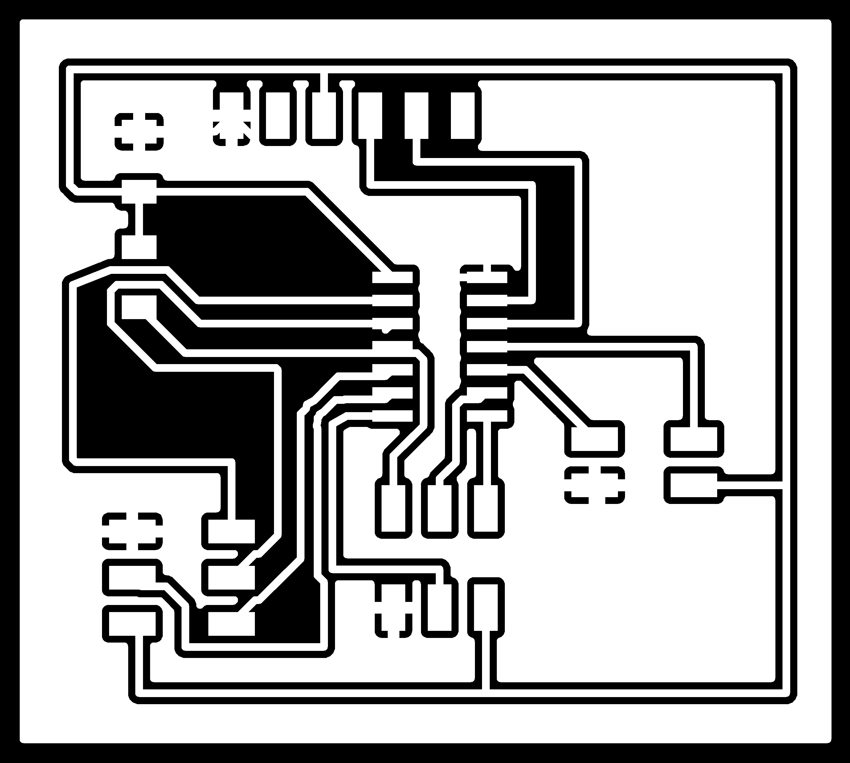
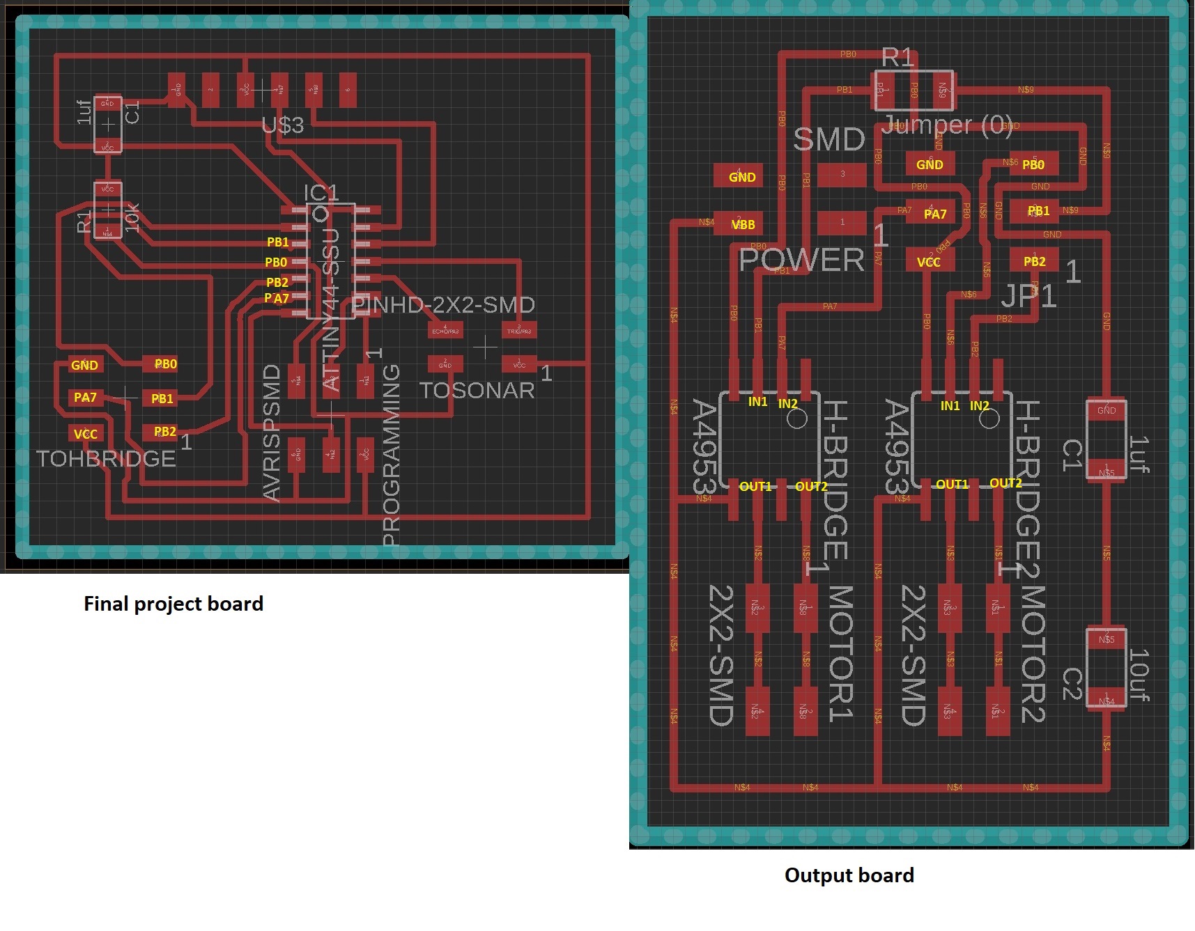
Here is my schema
And my board
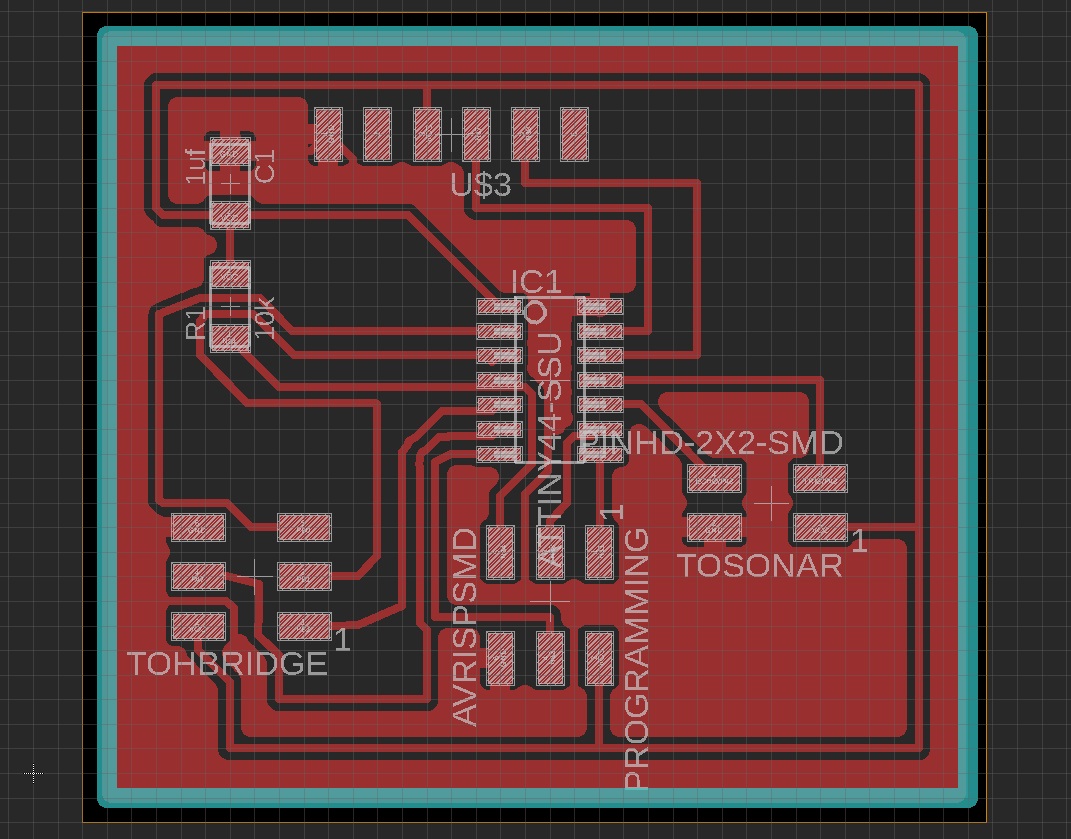
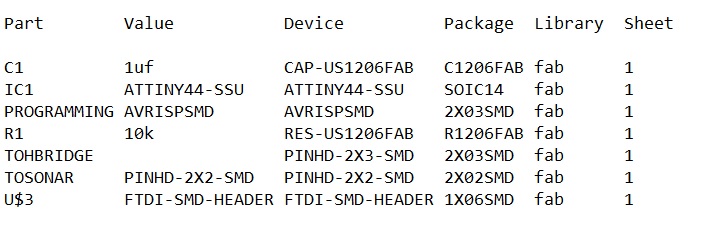
Here is the part list
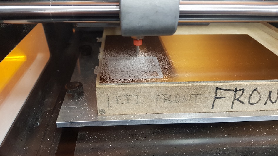
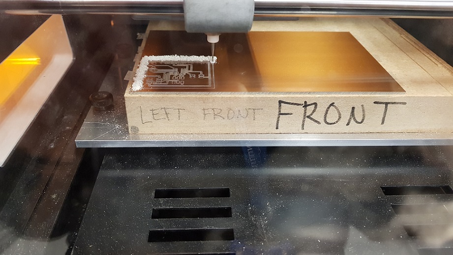
When machining the board I used the workflows identified on week 5 of Fabacademy. I exported the traces and outline files from Eagle as png files, went to fabModules website to modify the milling machine specifications so that the board comes out right. The instructions for the machine were saved as rml files to the computer.
I took my rml files and milled them out with the Roland SRM milling machine. A photo of my traces being milled
A photo of my outline being milled
soldering went by without pausing for pictures. But here is my finished board. I tested it with a multimeter, and all seemed to be in working order.
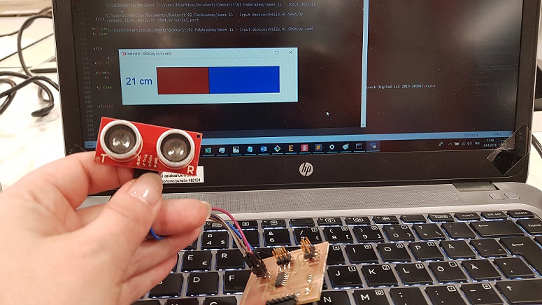
Now it was time to start programming it. I used Atmel studio and started with Neils HelloHC-SR04 code. As I did not use his schema, and used Attiny44 instead of AtTiny45 I modified the code a bit. Whenever I did any changes, I marked it with a comment
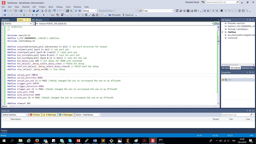
After this, I installed python 2.7.14 into my computer, and used Neil's python code for picturing values from the sonar. I was able to run the program successfully, but it was not actually measuring anything. I tried the device in both Com3 and com6 ports but no difference - The number stayed at 0.33 whatever I did, and every time I ran the program, it stopped responding. Eventually I found out that the clock in the ATtinys is different, and because of this it might not work. I heard that Jari from our FabLab had also switched from Attiny45 to attiny44 in his project, so I might find luck with looking at his page. Sure enough, he had changed the clock to be 8Mhz (8000000UL) instead of the 20Mhz (20000000UL). I changed this value from my code, and the sonar was working - behold:
Files
- FinalProject.sch schema file
- FinalProject.brd design file
- Traces .png file
- Outline .png file
- Traces .rml file
- Outline .rml file
- Sonar for Attiny44 .c code
W12: Throwing in 2 H-bridges and DC motors
This week I built a board to connect to main main project board, that houses the two H-Bridges for 2 DC motors. With this board I will be able to add an output part for the robot. This did not go without glitches. I think I was still working on these on W16. You can read the whole story from Week 12 documentation, below is a summary.
This week I continued to work on the output part of the robot, adding a board with 2 A4953 H-bridge motor drivers and two pin headers for 2 DC motors that move the wheels. The aim was to connect this board to the final project board designed the week before, and to test that it works with Neil's existing code.
The basic principle of work for the H-Bridge according to the datasheet:
- Designed for pulse width modulated (PWM) control of DC motors
- Capable of peak output currents to ±2 A and operating voltages to 40 V.
- Input terminals provided for use in controlling the speed and direction of a DC motor with externally applied PWM control signals.
- Internal synchronous rectification control circuitry provided to lower power dissipation during PWM operation.
- Internal circuit protection includes overcurrent protection, motor lead short to ground or supply, thermal shutdown with hysteresis, undervoltage monitoring of VBB, and crossovercurrent protection.
Here is the pin-out diagram from the datasheet
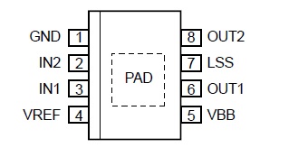
GND: Pin 1 is Ground
IN1: Pin 3 is Logic input 1
IN2: Pin 2 is Logic input 2
LSS: Pin 7 is Power return – sense resistor connection
OUT1: Pin 6 is DMOS full bridge output 1
OUT2: Pin 8 is DMOS full bridge output 2
VBB: Pin 5 is Load supply voltage
VREF: Pin 4 is Analog input
PAD: Exposed pad for enhanced thermal dissipation in the bottom of the component
I studied Neil's hello.H-Bridge board layout, components photo, and dc motor video. Neil had also included C code to test the board with. Then I discussed this week's project with out local instructor Juha-Pekka, and started to tinker with Eagle on my own. The design was a process of trial and error - I had misunderstood how the H-Bridge works, and had at first not included connecting pins, then I had drawn lines underneath the component which was a total no-no. Here Ivan helped me figure out my errors, and pushed me forwards. The third design was the first one that was OK.
Here is the final version of the output board
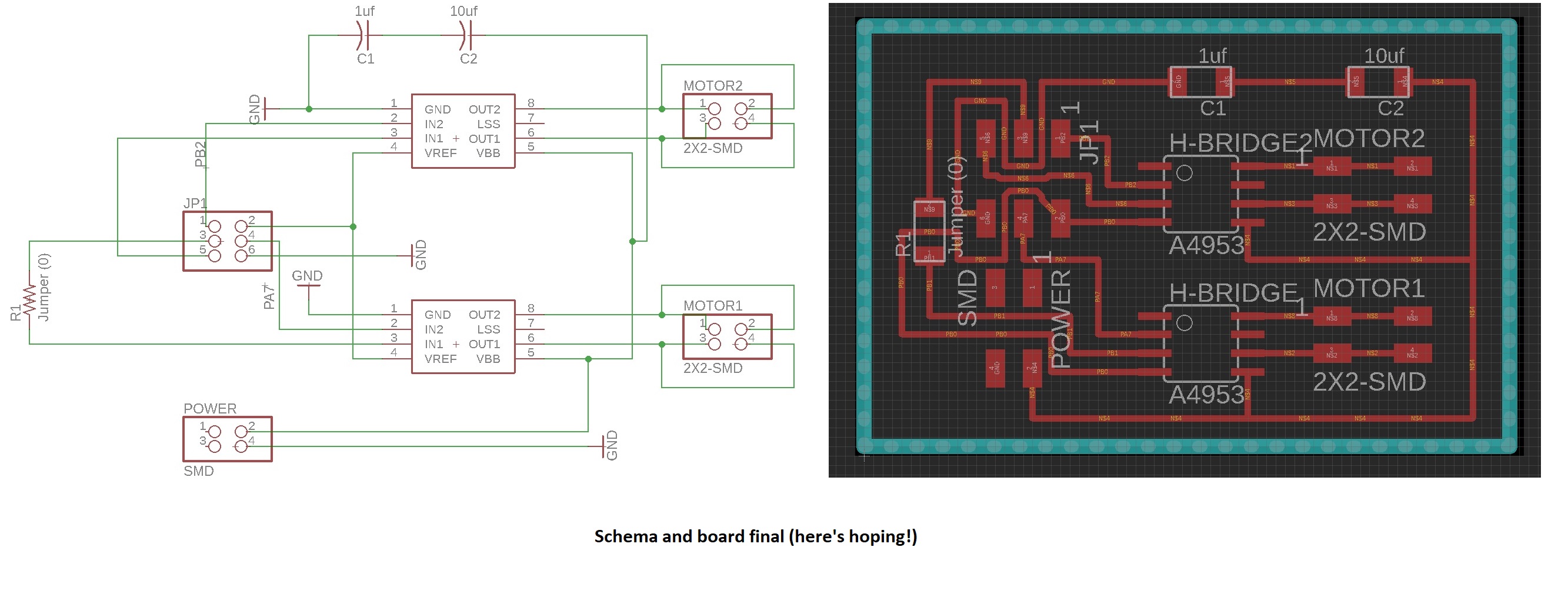
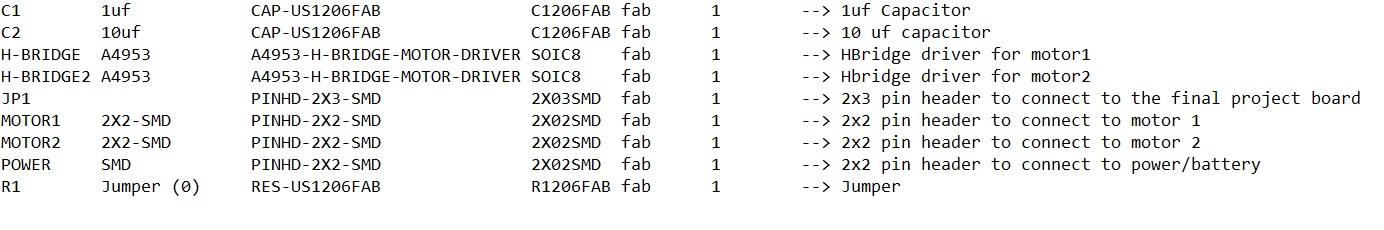
and the partlist
I again exported the traces and outline files from Eagle as png files, went to fabModules website tomodify the milling machine specifications so that the board comes out right. They were saved as rml files to the computer. Then I took my rml trace and outline files and headed towards the milling machine and the computer that it is controlled with and milled them out.
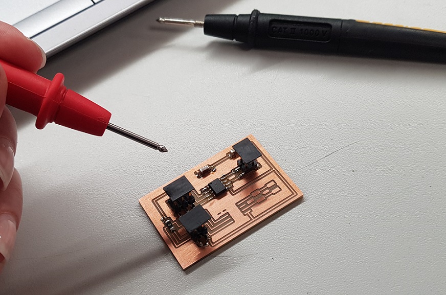
After this, it was time to solder in the components keeping an eye on my board picture for reference. I was advised by Ivan to first just solder one of the H-bridges and connected pin headers to the board for testing, if there was a problem with the components, it would be much easier to isolate the problem this way. Here is my finished "halfboard". I tested it with a multimeter, and all seemed to be in working order.
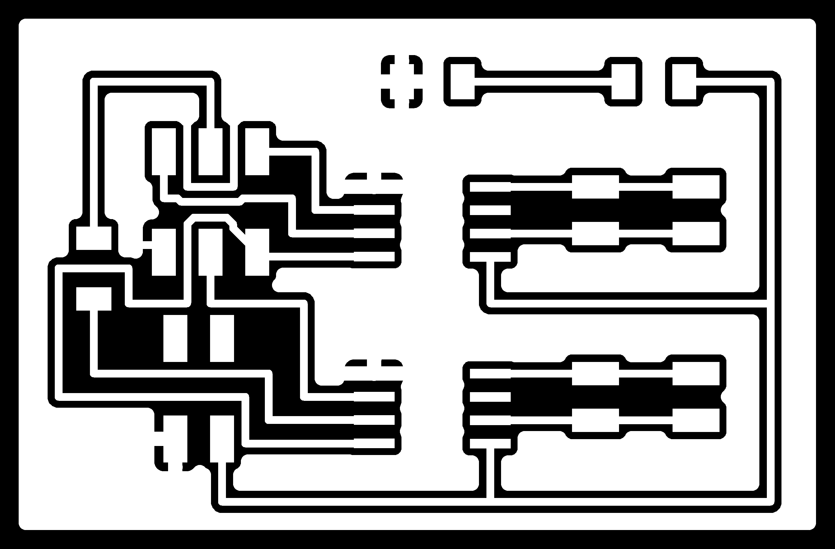
Next I connected the 2x3 pinheaders in the final project board to the corresponding pins in the H-bridge board according to specified my Eagle file pictured below.
I carried out the pogramming part of the assignment using Atmel studio, using Neil's hello.Hbridge44.c code. I only changed the pin numbers on the code to correspond to those in my design, and added the F_CPU to be 8 mhz as earlier in input week. I did no changes to the main code. Everything went through beautifully. I got a dc motor from Ivan for testing, attached it to the H-Bridge board with a 9v battery.

but when I tested the code, nothing worked. I did a lot of troubleshooting over the next days (or weeks), and had a lot of people help me. My local instructors, Jani, Antti, Ivan and Jari, and my fellow students Ari and Jari to name a few. It was a total puzzle.
Among other things while troubleshooting we tested:
- The battery and the motor work - We got the motor running with the straight connection
- My final project board and FabISP still work, I reprogrammed the sonar code there, all good and working
- I checked some of previous years FabAcademy student files (Grace Copplestone, Robert Hart, Randi Williams), as well as Neil's board and in the datasheet:
-- Found that "For optimum electrical and thermal performance, the A4952/A4953 must be soldered directly onto the board. On the underside of the A4952/A4953 package is an exposed pad, which provides a path for enhanced thermal dissipation. The thermal pad must be soldered directly to an exposed surface on the PCB in order to achieve optimal thermal conduction. Thermal vias are used to transfer heat to other layers of the PCB." --> The local instructors believed that the H-bridge should work even without having the pad attached. Nonetheless, we tested this with the other H-Bridge (also the thermal pad) and the 2*2 pin header to my board (changed Neil's the code to fit the new pins), and connected the motor to the new H-Bridge. Did not work.
-- Found that: "In order to use PWM current control, a low-value resistor is placed between the LSS pin and ground for current sensing purposes. To minimize ground-trace IR drops in sensing the output current level, the current sensing resistor should have an independent ground return to the star ground point."--> We connected the LSS pins to ground while troubleshooting with Jari (not through a resistor though),this did not work. Next as advised by our lab leader Jani, I added the low value resistor to the LSS pin of the other H-Bridge. This still did not work
-- Found that: "The load supply pin, VBB, should be decoupled with an electrolytic capacitor (typically 100 μF) in parallel with a lower valued ceramic capacitor placed as close as practicable to the device." --> I have 2 capacitors, so this should be OK, buuuut - I also have 2 Hbridges. Should I also have 2 more capacitors? If not, could the capacitor be too far from the H-Bridges? I spoke to the lab leader Jani, who believes this should not be an issue. He did take a look at my documentation though, and said that one problem with the capacitors is that they are now in a series (sarjana) when they should be parallel (rinnakkain). I therefore unsoldered one of the capacitors, connected one end to the pad, and one on the ground, and added a jumper. Didn't work.
Finally we checked the board once more with Ivan, Jari and Antti from our lab helping me troubleshoot. We checked how much power it takes to run the motor that I was using. It seems that more than it was getting. I connected my board to a another DC motor by Jameco, and it worked fine, also with the other motor connected. Now I -just- have to come up with a way to make the motors react to data from the sonar.
Files
- H-Bridge board .sch schema file
- H-Bridge board.brd design file
- Traces .png file
- Outline .png file
- Traces .rml file
- Outline .rml file
- Both H-bridges and the sonar C code combined
W17:Building a base for my robot
This week I built a composite base for the robot using a two sided mold. Below is a summary, you can also read more from Week 17 documentation.
Summary
I designed a two sided mold in fusion 360
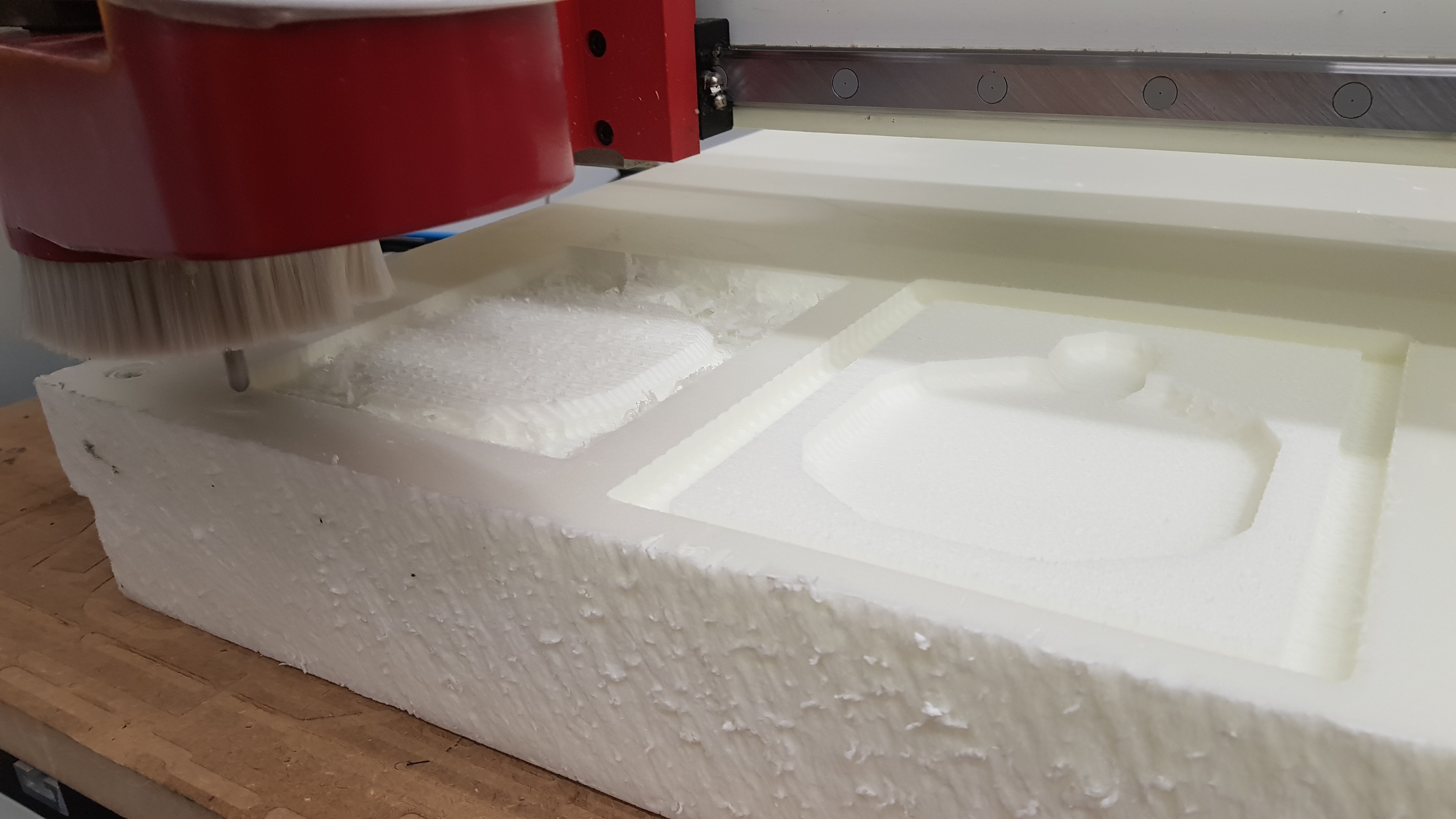
I prepared the mold for machining in CAM
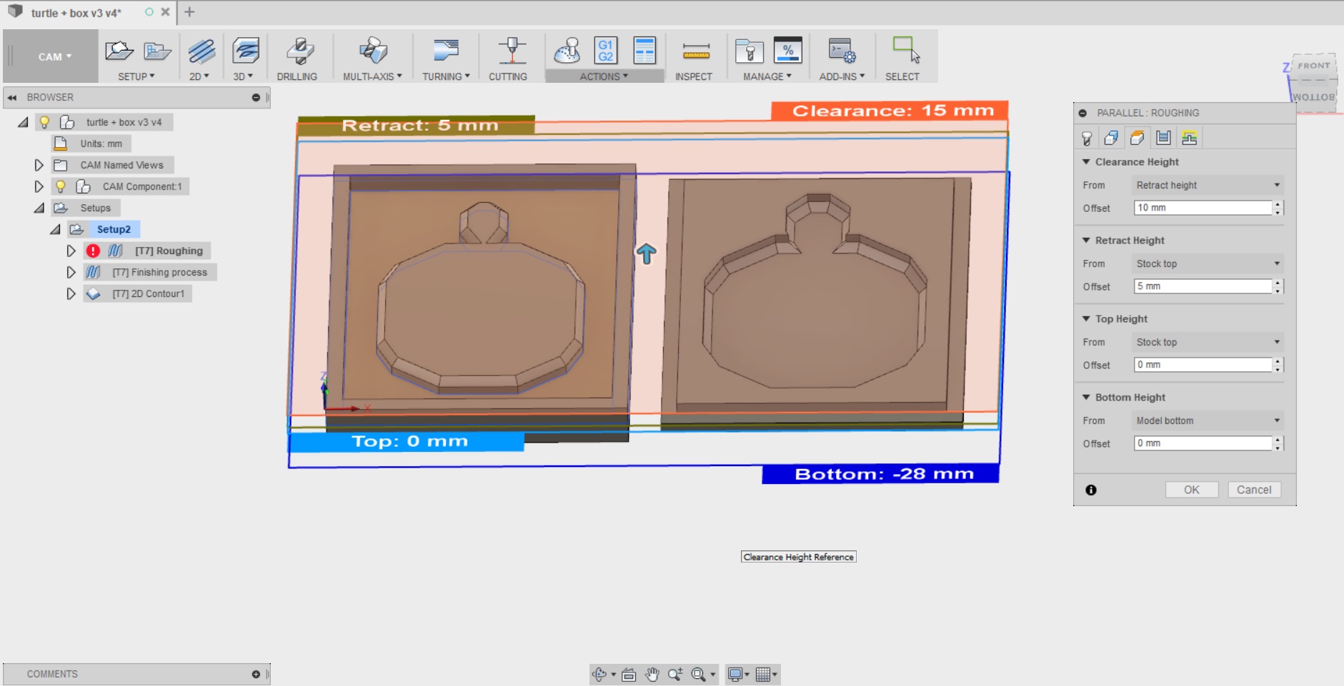
I cut out the mold with a CNC machine in XPS sheets that are 2x50mm thick
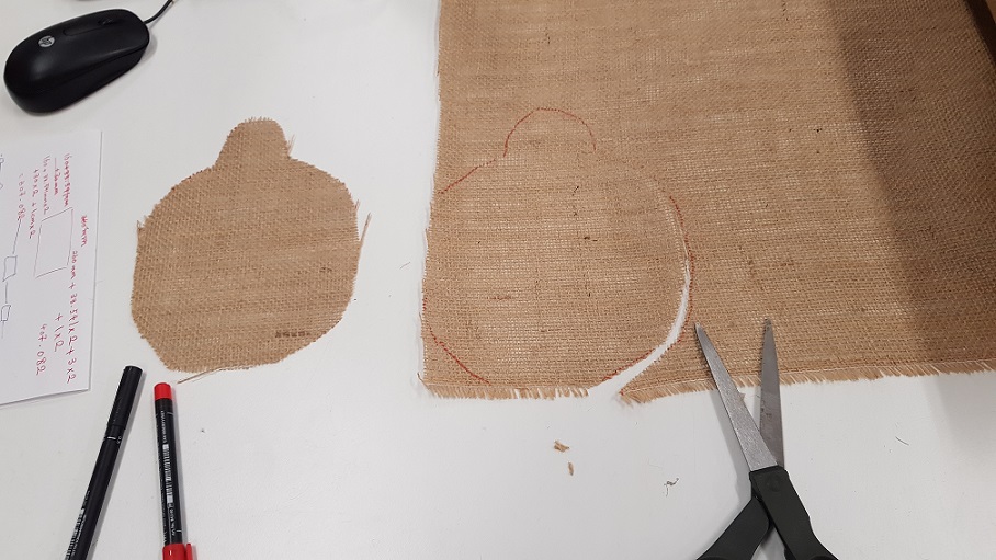
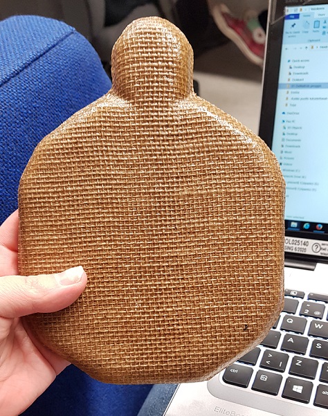
I cut out 9 layers of burlab sack, in pieces that are roughly big enough to cover the turtle shape in the mold.
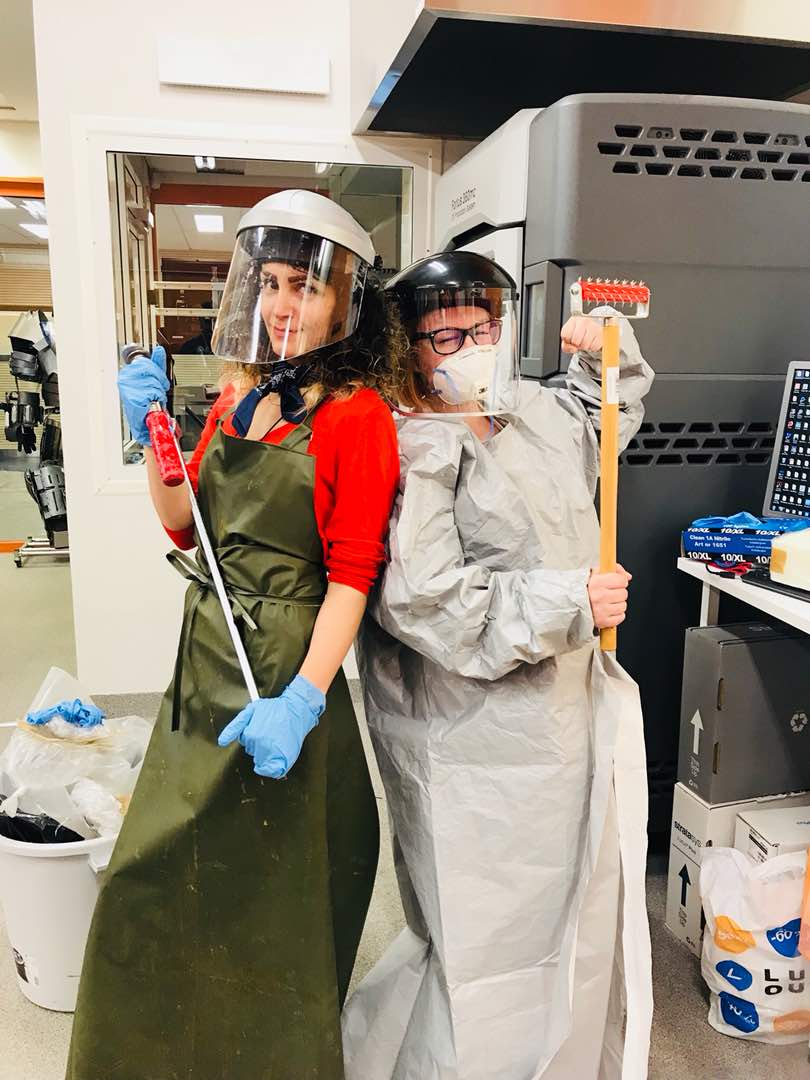
- I used plastic to cover the working area, and got me some good protective gear
- For laminating the burlab fabric I used SUPER SAP 100/1000 SYSTEM which is composed of part A) Super Sap 100 Epoxy (a modified, liquid epoxy resin), and part B) Super Sap 1000 Hardener. When the composite was ready, it was left in compression overnight
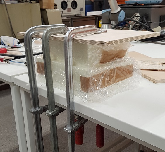
Here is the final result
Files
- The design file for the mold with the CAM and post process done
- The stl file for the mold with the CAM and post process done
- The roughing nc code for machining
- The finishing nc code for machining
W20: Nothing motivates you like a good old panic
Tuesday 12.6
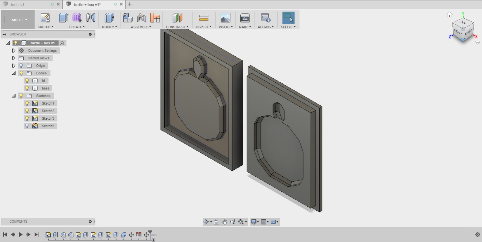
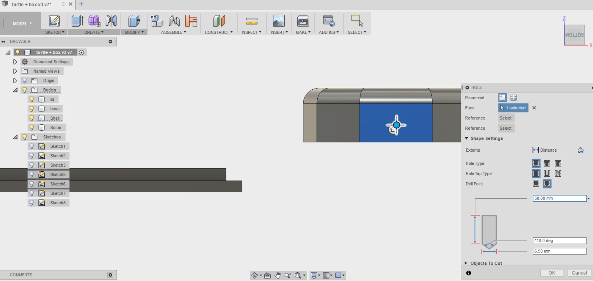
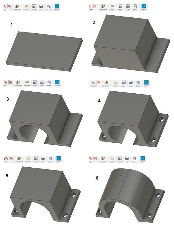
I 3d designed the shell for the turtle, in the same file as the mold I had used for the base of the turtle so I would get the shape and the measurements done easily.
- When the model of the shell was ready, I created a shape to represent the sonar
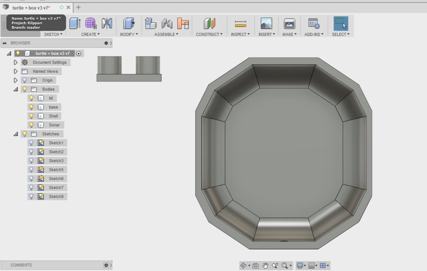
- And used it as a tool to cut holes for the sonar to the front of the model
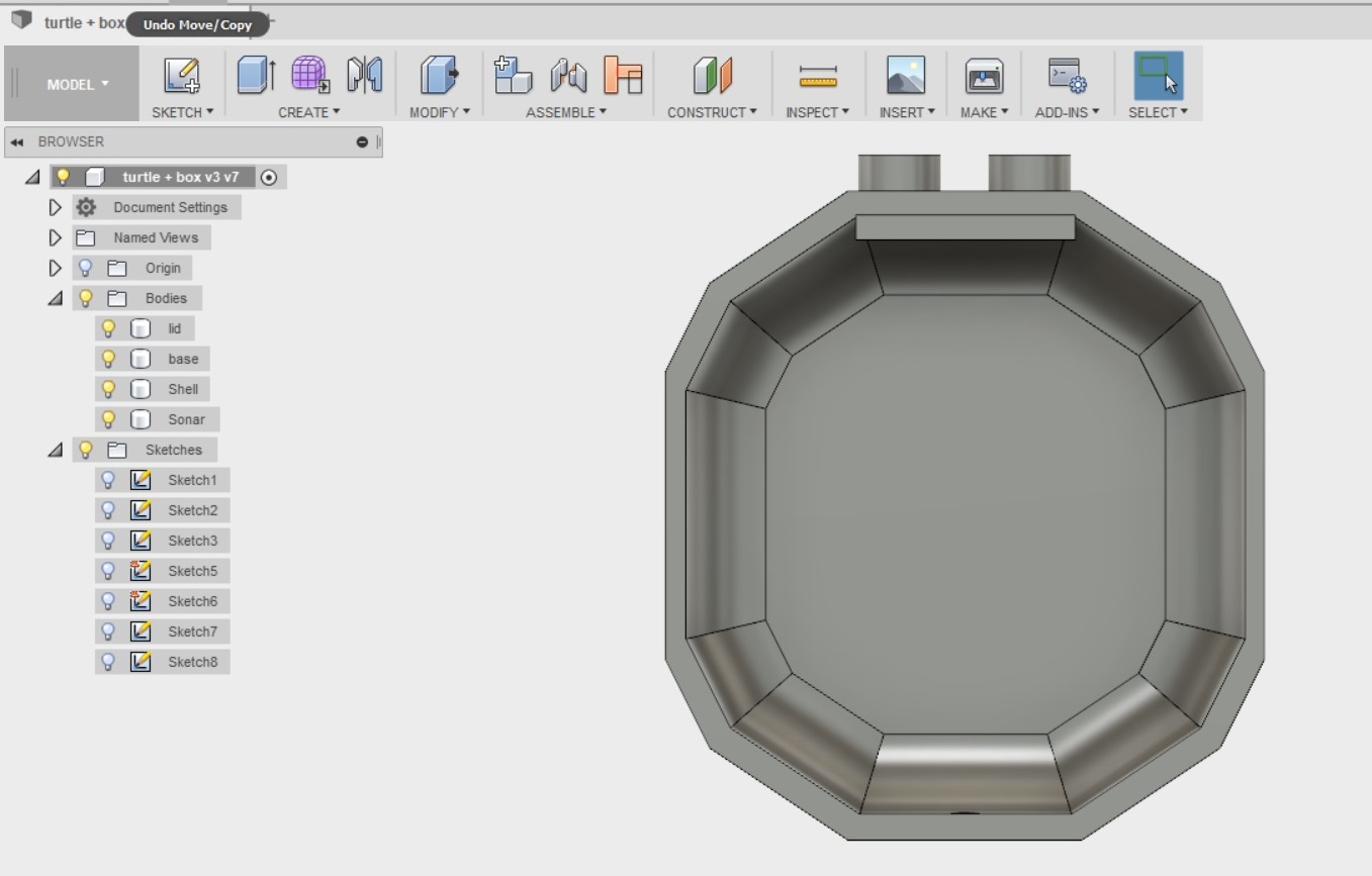
- I also created a whole in the back of the model for the switch to turn on the robot
I printed the model out using the big Stratasys 3D printer at FabLab oulu. The printing used ABS, and took about 2 hours 30 mins.
Here is the ready model. As there was so much support material left, I soaked it in lye overnight
- While the print was soaking, I started thinking about those sweet wheels I needed to fashion, and decided to lasercut them. I also decided to add some small decorations to pimp my ride. I made sure the lines I wanted to cut out were 0.020mm wide.
Wednesday 13.6
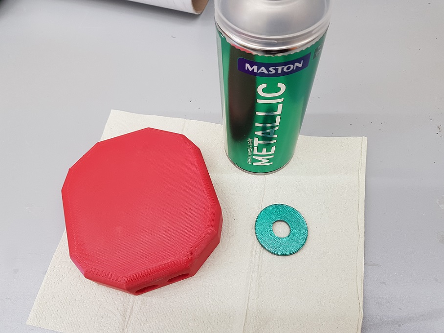
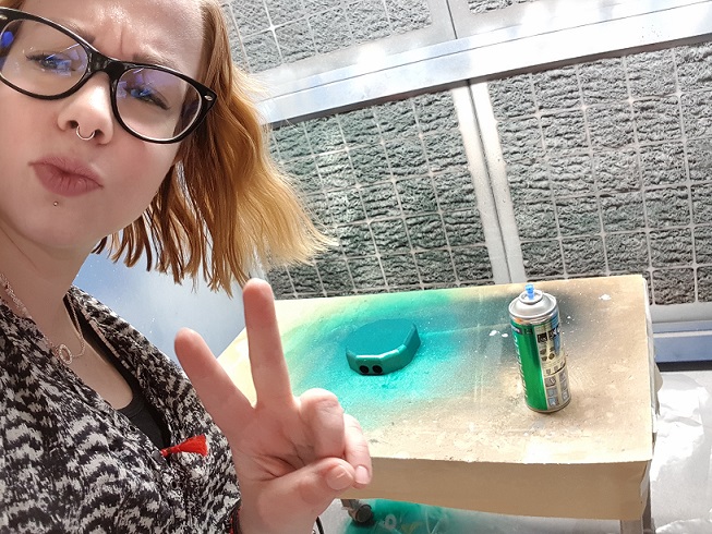
I picked up my 3D print from lye and washed it. I decided to paint it - After all. What turtle has a red shell? I opted for Maston metallic spraypaint, and decided to do a small test piece of the same material while I was waiting for my model to dry properly. It turned out great.
I also discussed how to solve my problem of the Attiny needing 5V to operate, and the motors needing 9V with our local instructors Antti and Jari. I was powering the attiny44 through the ftdi cable and the motors with a battery. This did not seem like a sustainable choice unless I wanted to run by the turtle with my laptop when I wanted it to move.
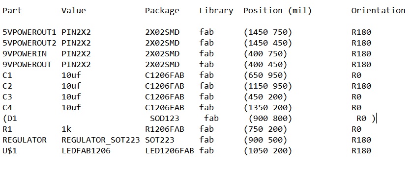
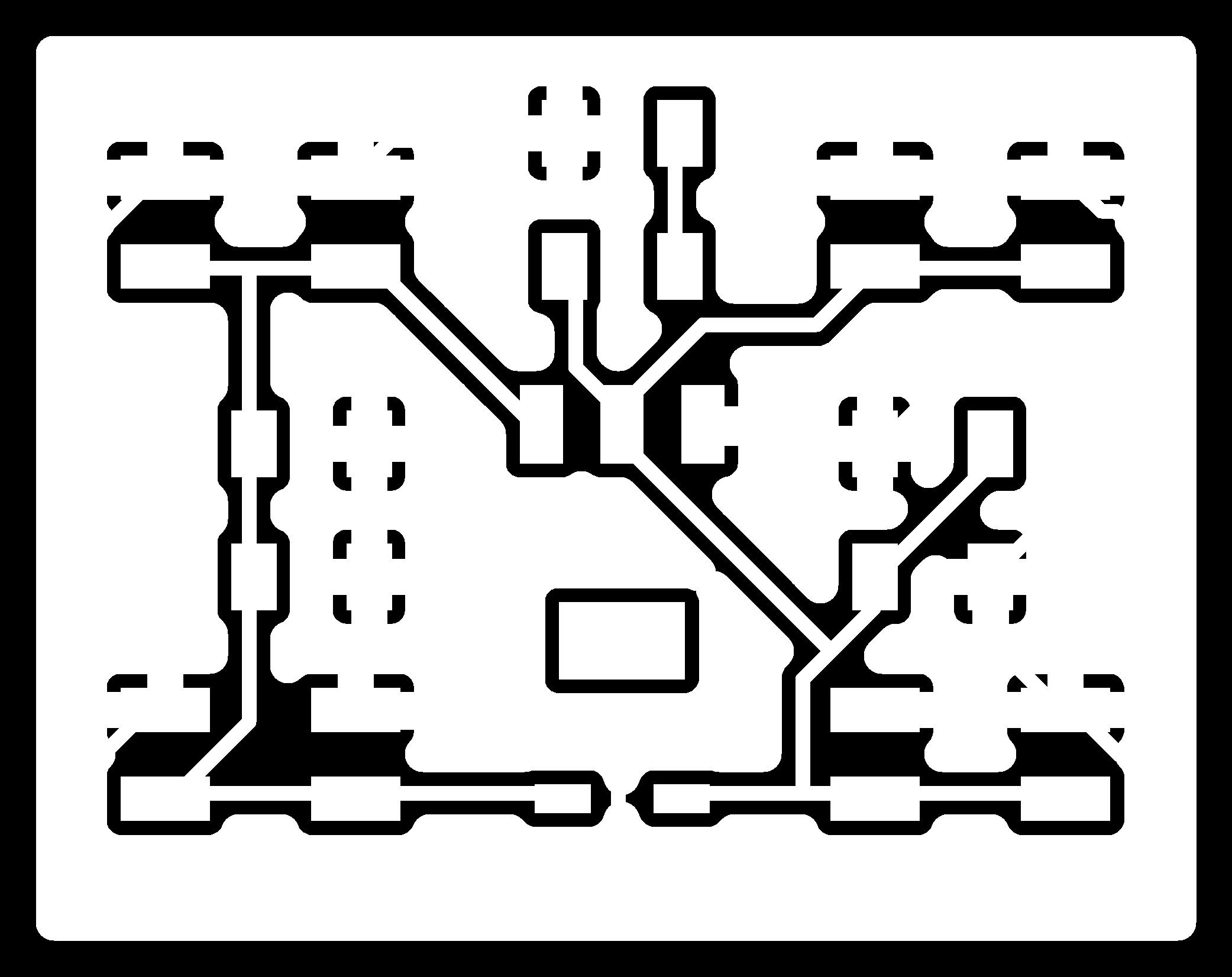
I solved the problem by adding a third board into my design that features a 4 pin headers and a regulator. 1 pin header takes the 9V input from the battery, 1 pin header carries the 9V to the H, bridges. In the middle there is a regulator that turns the voltage down to 5V for the remaining two pin headers. 1 pin header then carries the 5V to the Attiny44, and the last one can be used for possible future additions to the design.
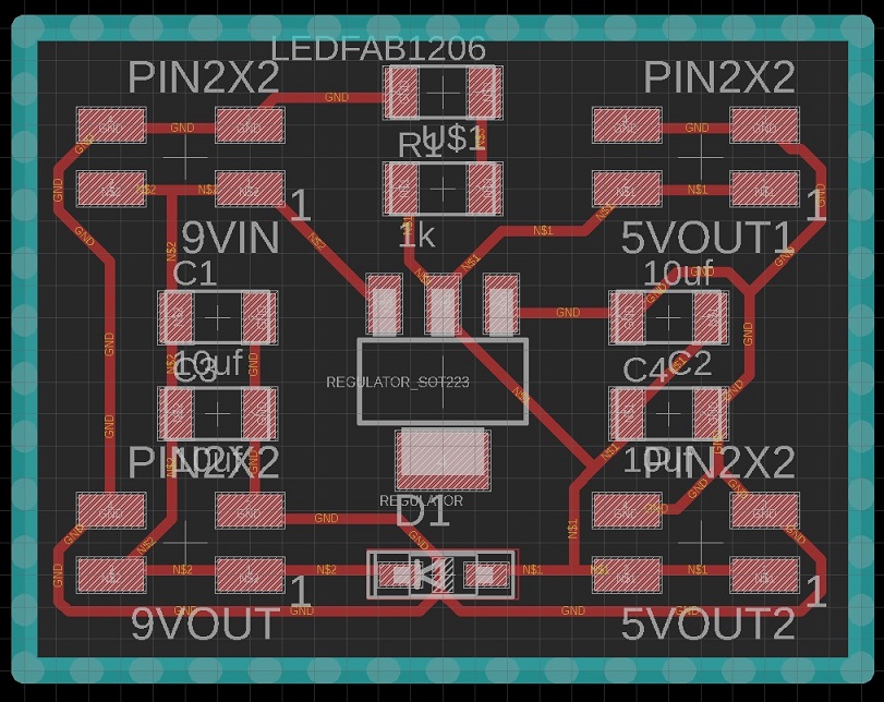
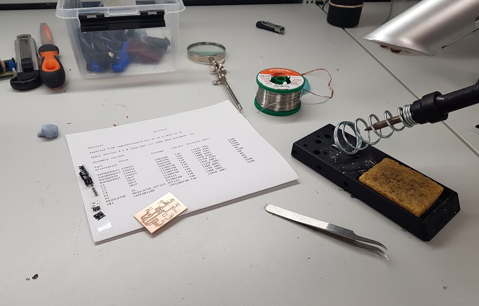
Here is the partlist
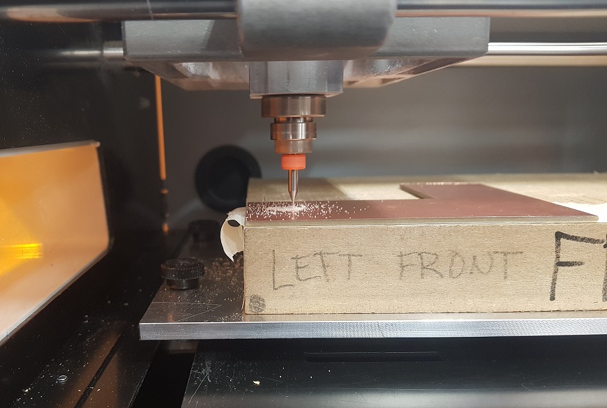
milled it out
and stuffed it in the lab
I actually did two versions of this board. At first I had made the mistake of drawing the pin headers too close to each other so that the connectors would not fit properly. See pic below.
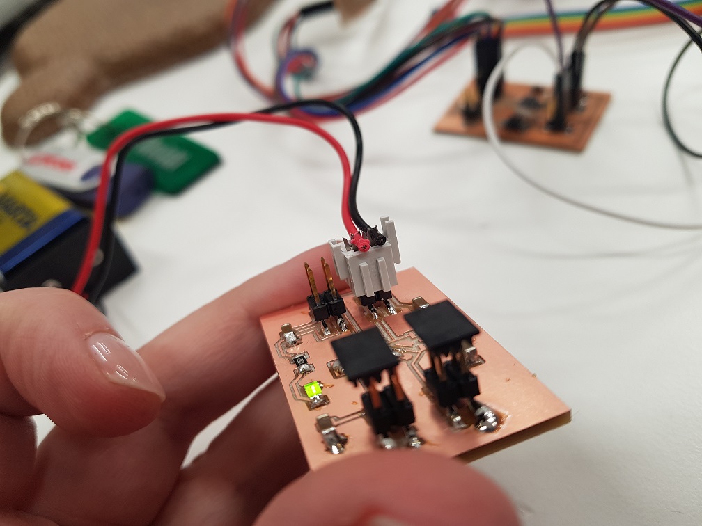
I revised the design, milled and soldered again. Later (with a little help from Jari, and my fellow FabAcademy student Ari) I noticed that the original design would have also worked, if I had just turned the connectors to face each other. Another one of those "doh" moments for me
Thursday 14.6
Trusting that my 3D mold had dried enough, I decided to spraypaint it. I went into our painting space, turned on the fume hood, protected all surfaces, and started painting. Being an old friend of Maston Metallic, I trusted that I didn't need a primer paint, even though it was suggested on the side of the can. As advised, I first shook the can for a couple of minutes, then did several thin layers on the shell, waiting for 5 minutes between layers.
Never too old for a bit of the duckface. Looking cool
Rather than watching the paint to dry for the rest of the day, I then decided to tackle rather pressing issue - How to attach the motors to the base. At first I went through all the lazy person options:
- Could I use a glue gun?
The answer is no. The composite base is slippery. Very slippery. Nothing seems to stick to it.
- Could I drill a couple of holes through the composite and connect the motors with cable ties?
The answer is - possibly - but I was told by my local advisors that the motors might wiggle and cause the robot to turn
There was no other option. It was back to fusion360.
I did quite a simple design.
1. I first drew a small box, extruded it 3mm.
2. Drew another smaller box on top if it, extruded that 30mm.
3. Cut a hole through the boxes that is the size of the motors
4. Cut small holes to screw the mount to the base
5. trimmed the extra from the sides of the hole
6. used a fillet tool to round any sharp edges
Printed two of these out with the stratasys printer from the same ABS as the shell of the turtle. Printing took about 1.5 hours. I was able to remove all support material by hand so I didn't need to put these in the lye tank.
Today I also cut out some texts and decorations for the robot, prepared on inkscape, and cut out on black vinyl stickers
Friday 15.6
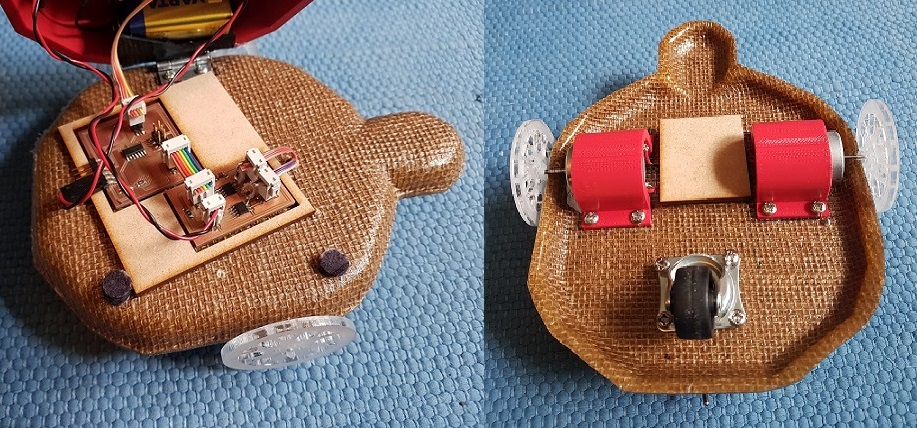
On friday, the first thing I did, was to drill a hole through the composite base of the turtle, and connected the motors to the base using the motormounts.
I had some trouble finding screws that are small enough not to go through, and even managed to break one inside the composite. Sometimes I just do not realize how strong I am :|
Next it was time to do the cables. I almost broke my brain doing this, as I had previously only used the arduino test cables. I had to keep checking all over and over that all was connected properly as I was afraid of frying something up. To help me with this, I went back to my eagle design files - Kept the board picture open all of the time, connect one cable at a time, and check that all was still working.
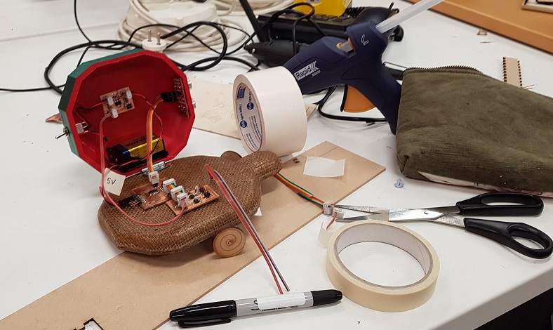
Then I connected the wheels to the motors. I attached the press-fit lasercut wheels in place with a hot glue gun so they would not move back and forth. I also added a small furniture wheel in the back to keep the butt of the turtle from dragging the ground. The wheel in the back turns freely
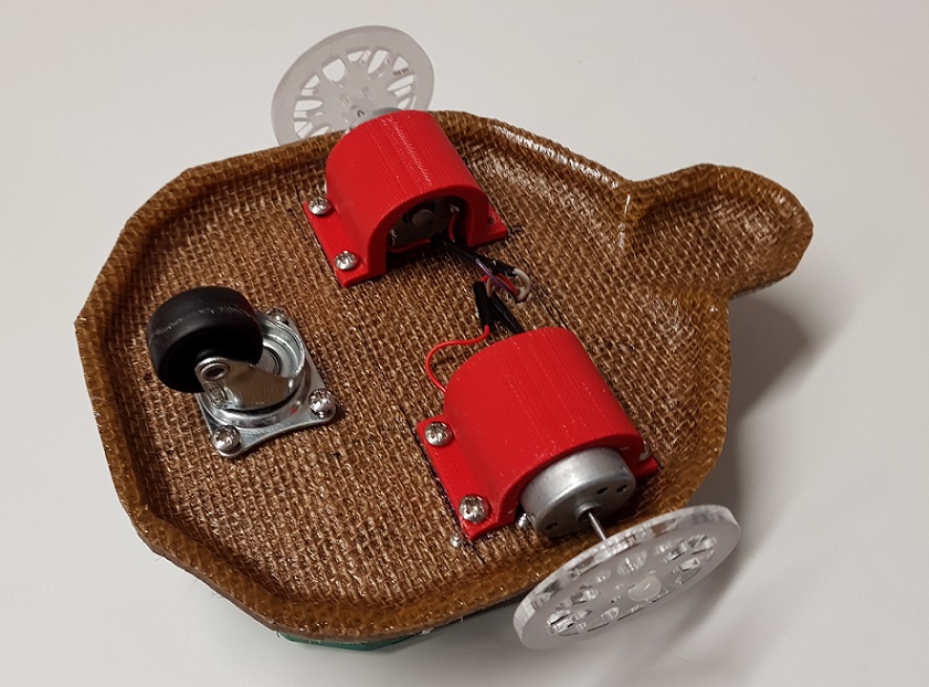
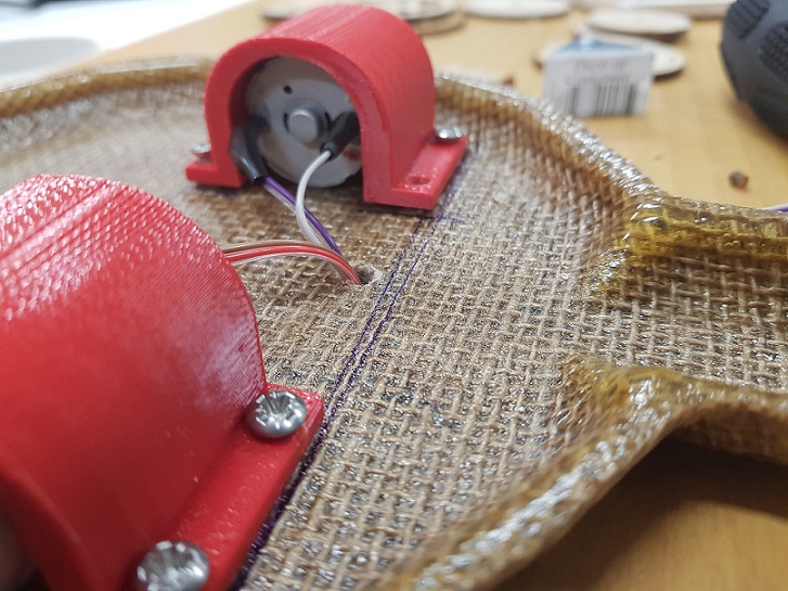
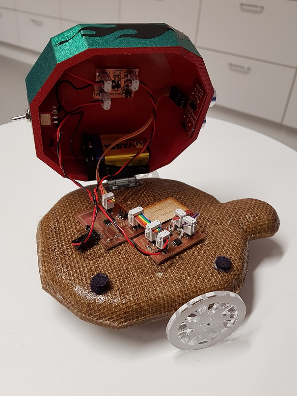
I attached the shell to the base with a small store bought hinge. I attached it with screws, even though it was a pity to drill more holes into the composite. This was however necessary - As I mentioned previously, nothing seems to stick to the composite.
Attached bonus with the shell - It can now hold some of the electronics - This is good, I think looks nice and clean.
Saturday 16.6, sunday 17.6
Saturday was the day - the day for programming. I had dreaded this so much. It was my first go with Arduino, and I was equipped with two ready codes that I wanted to test out.
- The first one was Kumar Gupta's Obstacle avoiding robot code on instructables
- The second one FabAcademy 2016 final project by Muhammed Safwan
The basic functionality in both of these was the same. Read values from the sonar constantly, if you are closer than, say 30cm to a wall, turn right. Muhammed's code uses a dedicated library to do the conversion from sonar values to cm, while Kumar's code does the conversion in the code. Both do exactly what I wanted. Should be straight forward, right?
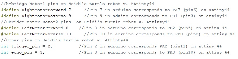
Wrong. I fiddled with both of these quite a while. For two days to be exact. At first I tested the obstacle avoider code, only changing the sonar and the motor pins to connect to those on my attiny. I used to the very helpful image from my fellow student Jari Uusitalo's page in this.
Here are my pins for the sonar and the h-bridges defined in the arduino code.
I uploaded the code from Arduino IDE to the Attiny44 with the programmer created on electronics production week without any glitches. I was very happy. And it worked in theory:
- When I held the robot in my hand and pointed at an obstacle, the right motor stopped moving, and the left one kept on going.
- When I held the robot up to face the ceiling, both motors started up again
This is just what the code was supposed to do. However, when I put the robot to the floor at the fablab, it just kept going in circles.
I did not understand why.
At first I uploaded Muhammed's code (again changing the pins) to the Attiny, thinking that it might be a code issue. It was not. The motors behaved the same with both codes.
- Then I thought that it might be a weight issue - the robot is quite heavy, and I was thinking, that maybe when the back wheel starts turning, it acts like a rudder/stern. When the robot starts rolling, the wheel sticks turns a bit, and dictates what direction the robot will move. The motors are not powerful enough to pull the wheel back straight. So I fixed the back wheel so that it will not rotate. Did not work
- Then I thought it might be some problem combining a possibly lazy right motor and slippery acrylic wheels not getting enough friction. I did new wheels using mdf, glueing several layers together. Did not work.
- Then I thought that the left motor might have more power. I lowered and lowered the analogWrite value for the left motor gradually to 150, while I kept the value for right motor 255. The result was, that the robot was not moving much at all.
- Then I though that maybe the sonar does not have enough time to update when it is rolling in circles - I made it so that when the robot faces an obstacle, it stops for a couple of seconds, then turns for a couple of seconds. This did not help either. It stops, but then just keeps going in a circle.
I think I made atleast ten different variations in the code over the weekend, changing one small thing, then compiling, seeing how the robot behaves, and going back to the drawing board. I was really frustrated, thinking I would never get the robot to behave like I wanted
Monday 18.6
After a pretty sleepless night I returned to the FabLab. Discussed with people, got me some ideas. The world was a happy place again
- I already knew that the sonar only has a 4m reach. I had noticed before that when the range is more than that, it thinks that it is against a wall (distance is 0cm). However, I did not put 2 and 2 together --> In a space as large as fablab, the reach was over 4 meters quite often, so the robot interpreted that as being close to and obstacle, and kept on rotating. I realized this when discussing this with my fellow fabstudent Martha.
I went back to the code. I selected to work on Muhammed Safwan's code as the basis, as I found it to be easier to understand. I however modified it quite a bit, with Martha helping me when I got stuck. Here are the changes that I did:
- I changed the pin numbering for the sonar and the H-Bridges to correspond to those in my attiny44
- The setup was the same --> Declaring the motor pins as outputs
The biggest difference was in the main loop, which you can see below
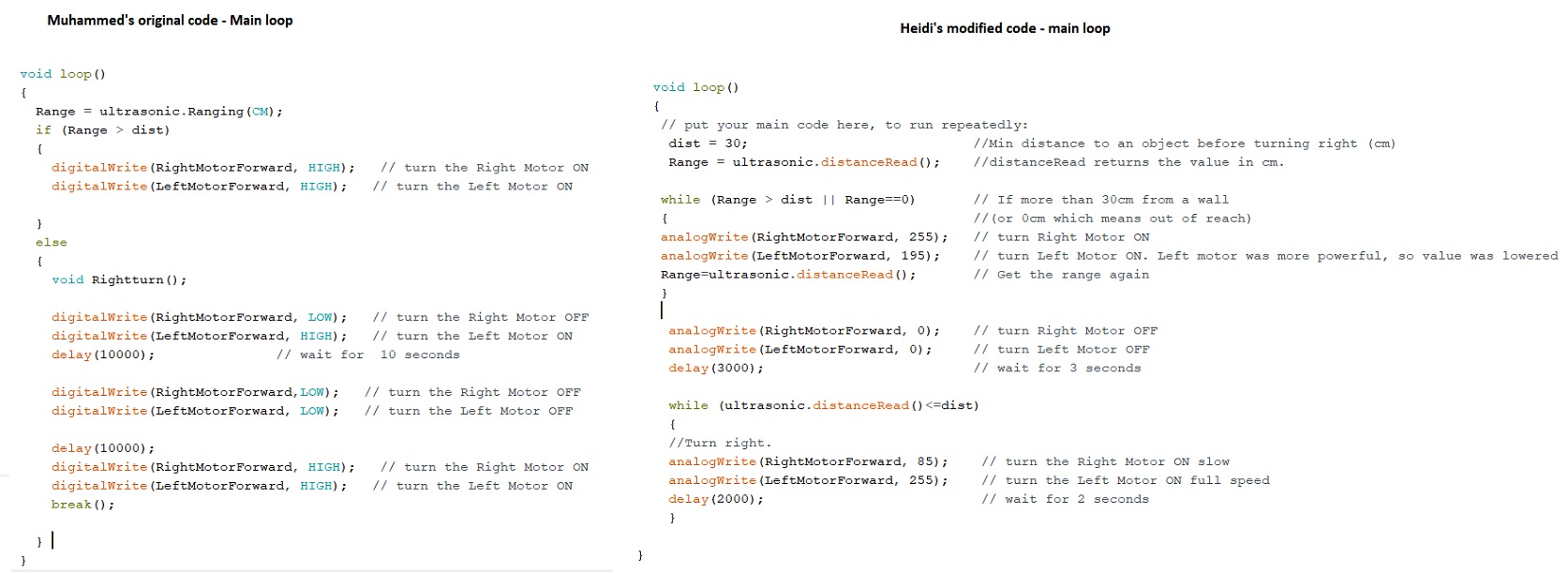
In my main loop:
- The min distance to an object is defined
- The sonar value is read (using distanceRead instead of Ranging)
- While sonar value is larger to 30cm OR if the sonar value is 0cm, which in our case would mean out of the sonar range
--- The robot goes forward (left motor moving slightly slower to take into account the differences in the motors)
--- The sonar value is read again
- Stop the motors for two seconds
- While sonar value is smaller or equal to 30 cm
-- Go forward for 3 seconds --> with the right motor moving a lot slower than the left motor in order to turn
And it is alive! Aliiiive!
I honestly could not stop smiling all day.
Tuesday 19.6
- Prepared my final presentation slide and video
- Updated my documentation
Wednesday 20.6
- Still added some better fixings for my electronics, before the final presentations. My local advisor Jani suggested a simple laser cut form with slots for the PCB's. For the design I used Inskcape.
- I also covered the wires in the bottom of the turtle coming from the motors to the PCB with a small mdf plate, which keeps the wires from getting stuck to anything that might be on the ground. The plate was just the inner part of the PCB slots from my electronics mount that were cut off with the laser
- I am thinking that the next version of the turtle that I do with the children, the electronics could be for example the shape of a heart, to represent the core of the turtle and include also laser engraved text "turtleBot", as well as the name of the child who produced the turtle, and the year the turtle was made.
Files
- Turtle mold, with the shell added, f3d
- Turtle shell, stl
- Motor mount, f3d
- Motor mount, stl
- Design for the first lasercutting (wheels and decorations), svg
- Design for the second lasercutting (different size wheels), svg
- Decals for vinylcutting, svg
- Text for vinylcutting, svg
- Electronics mounting, svg
- Regulator board
- Regulator board schema
- Regulator board traces, png
- Regulator board outline, png
- Regulator board traces, rml
- Regulator board outline, rml
- Arduino code for the robot
Bill of materials
On week 18 I did the first draft of the bill of materials for my project, and thought about what still needs to be done to be able to complete in time. The initial bill of materials can be seen in Week 18 documentation, below is the updated one.
| Material | Purpose | Quantity | Price | Origin |
|---|---|---|---|---|
| 2x50mm thick insulation sheathing (FinnFoam FL-300) | For creating the mold for the turtle robot. A sheet of 7.27m2 costs about 60.6$ (52e) | I eastimate I used max 1m2 for the mold | ~8$ | FabLab Inventory (Sourced locally) |
| Entropy resins epoxy and hardener for creating the base of the turtle robot. The big jugs cost 254.95$ | I estimate I used max 1/30 of the jugs for the base | ~8.5$ | FabLab Inventory | |
| LA Linen 15-Inch Natural Jute Burlap Roll | Material to laminate fo the base of the turtle robot. A 100-yard roll costs 50.90$ | I estimate I used max 1 meter (1.1 yards) of the roll for the base | ~0,509$ | FabLab Inventory |
| Polyester Batting | Breather fabric used when doing the composite. A roll costs 15.01$ | I estimate I used max 1/10 of the roll | 1,5$ | FabLab Inventory |
| Stretch Wrap | Used when doing the composite, to protect molds and to secure everything in place. A roll of 305m costs 29.09$ | I estimate I used less 2meters | 0,19$ | FabLab Inventory |
| 3D printer ABS M30 filament | Used when printing out the shell and the motor mounts on the stratasys 3D printer. A filament canister of 1500cm3 costs 350$ | I used 70.9cm3 of ABS for the shell which had a sparse interior sructure, and about half of this amount for the motor mounts which were solid. | ~25$ | FabLab Oulu Inventory |
| 3D printer support material | Used when printing out the shell and the motor mounts on the stratasys 3D printer. | I used 23.22cm3 of the support material for the shell which had a sparse interior sructure, and about the same amount for the motor mounts which were solid. | ???$ | FabLab Oulu Inventory |
| acrylic 3mm | For lasercutting the wheels of the robot. According to the Fab inventory this stuff is crazy expensive. 103.68$ per sheet? Or is it more sheets than one... | 0,5m2 | 5$? | Fab Lab Inventory |
| Maston metallic spraypaint can | Used to spraypaint the shell of the turtle. | I used much less than half a can of this stuff, but of course had to pay for the whole thing. Worth it | 9$ | Purchased |
| Black vinyl sticker | Used to cut out decals for the robot with the vinyl cutter. | 81.90$ per roll (45meters). I estimate I used max 20 cm. | ~0,5$ | FabLab Inventory |
| Furniture wheel | A small rotating wheel for the back of the robot | 1 | 3.5$ | Purchased |
| Hinge | A small hinge to attach the shell to the base | 1 | 3.5$ | Purchased |
| Misc screws | Small screws to attach motormouts, the backwheel, and the shell to the base | 16 pieces | 2$ | Purchased |
| TOTAL COST OF BASE | 68$ (~59 euros) |
Electronic parts and components
| Material | Purpose | Quantity | Price | Origin |
|---|---|---|---|---|
| Single side machineable PCB stock | For milling our the main project board, the H-Bridge board, and the regulator board | 1 | 1.40$ | FabLab Inventory |
| Soldering tin | To solder the components into the milled PCB. One roll costs approx 10$ | I estimate I have used max 1/10 of one roll | 1$ | FabLab Inventory |
| ATttiny44A-SSU-ND | Microcontroller to read values from Sonar and to send messages to H-Bridges | 1 | 1.18$ | FabLab Inventory |
| S1011EC-40-ND | ftdi 1X06SMD header to connect the main board to the computer. 40 pin piece á 0,60$ | 1*6 | 0,09$ | FabLab Inventory |
| Ultrasonic HC-SR04 | Sonar to read the distance from the obstacle | 1 | 4.495$ | FabLab Inventory |
| 620-1428-1-ND | A4953-H-BRIDGE Motor driver for DC motors. á 1.41$ | 2 | 2.82$ | FabLab Inventory |
| ZLDO1117G50DICT-ND | 5V regulator | 1 | 0.35$ | FabLab Inventory |
| DC motor | 12V DC motor from Jameco á 3.49$. To rotate the wheels | 2 | 6.98$ | Apparently these are not in Fablab inventory, but I was given 2 from the treasure cabinet at FabLab Oulu |
| 609-5161-1-ND | one 2*3 pin header for programming the ATTiny, two 2*3 pin headers to connect H-Bridge board to main project board. á 0.60$ | 3 | 1.80$ | FabLab Inventory |
| 609-5160-1-ND | 2*2 pin header: connect the sonar to the main board, connect two DC motors to the H-Bridge board, connect battery to regulator board, and to connect the regulator board to Hbridge board and to the Attiny board. á 0.66$ | 8 | 5.28$ | FabLab Inventory |
| 445-1423-1-ND | 1uf capacitors á 0.07$ | 2 | 0.14$ | FabLab Inventory |
| 587-1352-1-ND | 10uf capacitor | 5 á 0.18$ | 0.9$ | FabLab Inventory |
| 311-10.0KFRCT-ND | 10k resistor | 1 | 0.01$ | FabLab Inventory |
| 311-1.00KFRCT-ND | 1k resistor | 1 | 0.01$ | FabLab Inventory |
| 311-0.0ERCT-ND | 0 resistor(jumper) | 1 | 0.01$ | FabLab Inventory |
| 160-1167-1-ND | LED for the regulator board | 1 | 0.13$ | FabLab Inventory |
| BH9V-W-ND | Box to host hold a 9V battery | 1 | 1.27$ | FabLab Inventory |
| 9V battery | To power up the DC motors | 1 | 2.2$ | Purchased |
| Ribbon cable | To connect pin headers, battery, etc | One roll (1,5m) costs 38.07$. I used about 20cm | 5$ | FabLab Inventory |
| 2*2 connector sockets | To connect 2*2 pins | 8 a 0.55$ | 4.4$ | FabLab Inventory |
| 2*3 connector sockets | To connect 2*3 pins | 2 a 0.57$ | 1.14$ | FabLab Inventory | Toggle switch | To toggle power to the robot | 1 | ~2$ | FabLab Oulu Inventory |
| TOTAL COST OF ELECTRICAL COMPONENTS | 42,5$ (~ 37euros) |
Dissemination plan and license
On week 19 I thought about licensing issues and how to disseminate my project
. You can read the whole thing from Week 19 documentation.
Personally I am hoping I can use my work in the future with children who are participating in the digital fabrication related projects carried out with our research group. I wanted a simple project, something that the children would like to hack and modify - make their own. I think that I have succeeded, and I will be replicating this project in the fall with children from fifth and ninth grade, working in small groups.
I will do some tweaks, based on what I know now, at the end of the project. First of all, I need to find a way to make the robot less expensive. According to the current bill of materials the final cost of my robot is about 110$ (95 euros). That ain't cheap. I think that the biggest place where I could save up, would be skipping the composites for the base and the 3D printed shell, instead opting to lasercut the whole structure with the kids. It would also be more feasible. I wanted to explore the composite process during my time in the FabAcademy, but I do not think that many teachers or parents would be willing to try it out with the kids, as there are so many safety consideration with the chemicals used. Electronics design and production could also be replaced by using commercial boards, simplifying the project a bit.
In addition to hopefully using my final project as a basis for my own future research projects with children, I also want to share my work to a wider audience. I want anyone who is interested in any of the processes I learned about during my time in FabAcademy to be able to use my documentation as a basis for learning. In other words, I want my work to be available freely for educational purposes. Because of this, I selected to use Creative commons the "Attribution, ShareAlike, NonCommercial" -license for my project: "This license lets others remix, tweak, and build upon your work non-commercially, as long as they credit you and license their new creations under the identical terms" (Creative commons, 2018) In addition, I have selected to use the MIT license for all of the code produced during this project
Final presentation
My final presentation is scheduled for 20.6.2018. Below is the video and the slide
Copyright © Heidi Hartikainen 2018
Template copyright ©Blackrock Digital LLC 2013-2018

This work is licensed under a Creative Commons Attribution-NonCommercial-ShareAlike 4.0 International License.