Week 8: Computer-controlled machining
Group project:
Test runout, alignment, speeds, feeds, and toolpaths for your machine.
Individual project:
Make something big.
Design
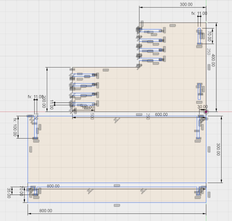
Idea was to make a desktop extension, so one can choose to stand and continue working with easy adjustment. I made a sketch with fusion 360.
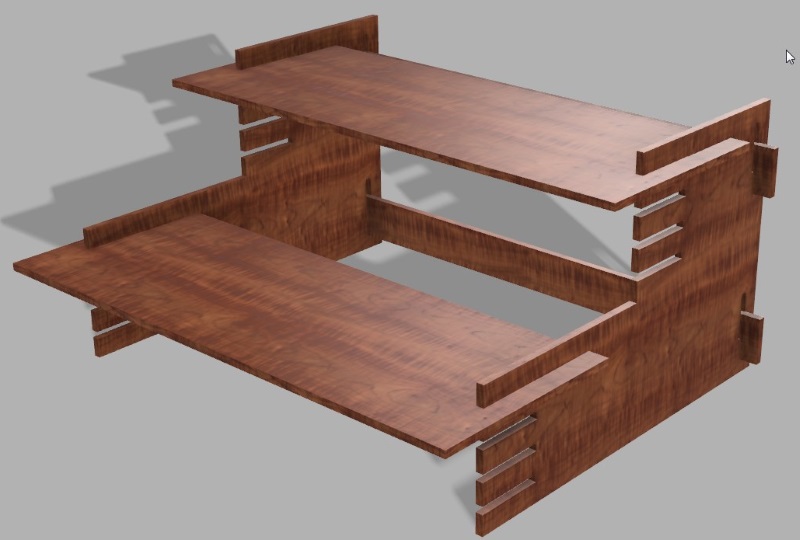
Extruded all the pieces and saved my project. I wanted to see how the model would look and to see if there were any design flaws, so I copied them as I needed two of everything. Moving them around and rotating a bit I built the model. And just for fun, took a detour at fusion's render section and applied cherry as material. Looks very nice, but sadly we have to do with compressed splinters.
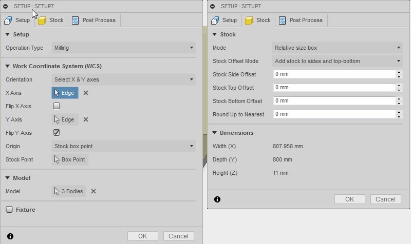
Opened up my project from earlier stage, since it had only 3 pieces and layout ready. Switched from Model to Cam in Fusion and went through the setup, by adjusting X/Y axis to point the right way(z points up, x left/right and y depth) and set point of origin(front left and top). Also removed stock offsets.
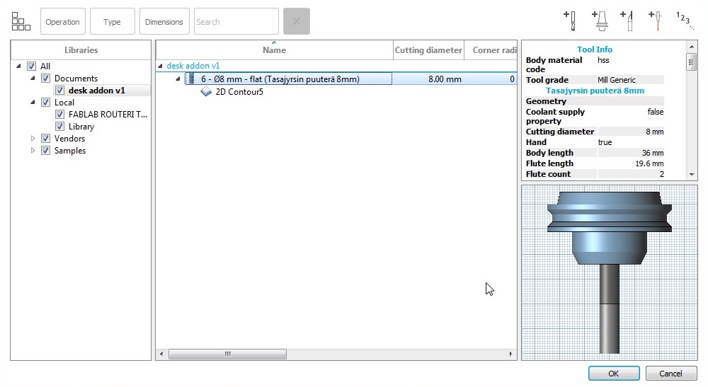
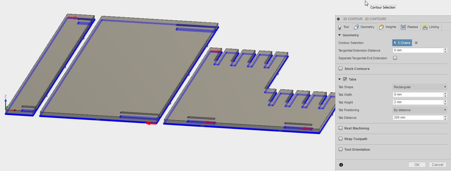
Created 2D contour. At this point I needed a tool file from our lab's wiki space, FABLAB ROUTERI TOOLS 2018-2.hsmlib, so I downloaded that and then imported it to local by rightclicking and selecting 'import tool library'. Then selected tool, 8mm flat under local, which is then copied to the project.
In Geometry, selected all contours from bottom. Clicked tabs on, so my pieces wouldnt get loose. 200 mm between felt enough, as well as 2mm height and 8mm width.
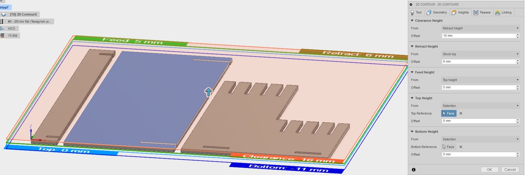
Set heights, by selecting top face to top height and bottom face for bottom height. For clearance, I left it untouched and increased rectract height from stock top to 6 mm.
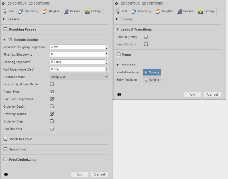
From passes checked Multiple Depths and changed Maximum Roughing Stepdown to 3mm and use Even Stepdowns to minimize stress to the tool. From Linking I toggled Lead-In and Lead-Out off.
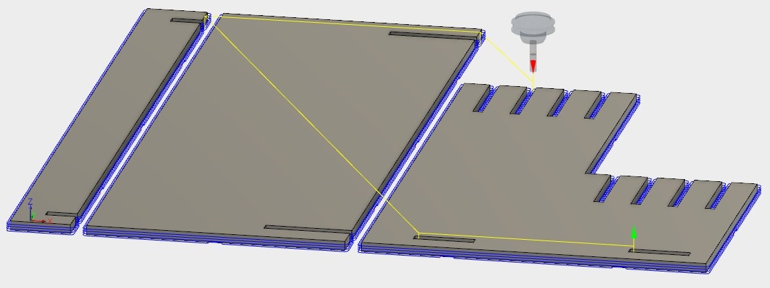
Clicking ok now creates toolpath. Everything seems ok.
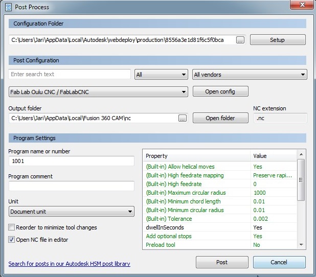
From actions menu opened post process. Very first line tell the location of the configuration file. Downloaded a "post processor file for Inventor/Fusion360" and moved it there. Then hit post and got my desk_track.nc file.
Milling
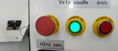
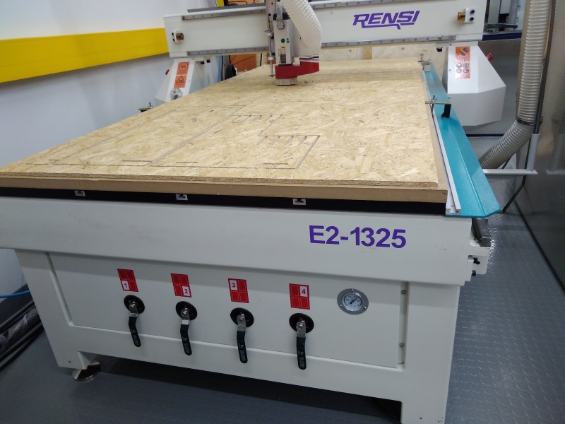
For setting up the CNC Milling Machine, I needed wood. So I picked up OSB board and attached it to the wooden platform with screws. When that was set up, I started the machine by switching on main power, and pushing power on button.
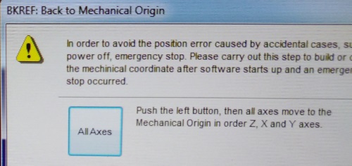
Then clicked software on and it instantly offered calibration. Clicked 'All axes' to set the machine back to mechanical origin.
Loaded my design by opening the path file I created(File > Open and load). Moved the milling bit to the point on the table I wanted to set new origin point, by pressing the control arrows on the software. Reseted x and y axes by clicking appropriate buttons next to the coordinates in the software. Manually set z axis, by setting spindle ON with 10% speed and lowered it to the surface until a faint sound could be heard, then resetted that as well.
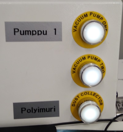
Right clicked on screen and selected clear from the menu that appeared. Then clicked simulate, to see how my design would look and see where it would be positioned. When everything was ready, I started vacuum pumps(tho need to use vacuum pumps if your plate is not wacuumed) and dust collector , set spindle to 70% and feed to 80%, and hitted play.
After milling was done, I cut tabs with carpet cutter and took my pieces off. After little bit of sanding, I assembled my project.
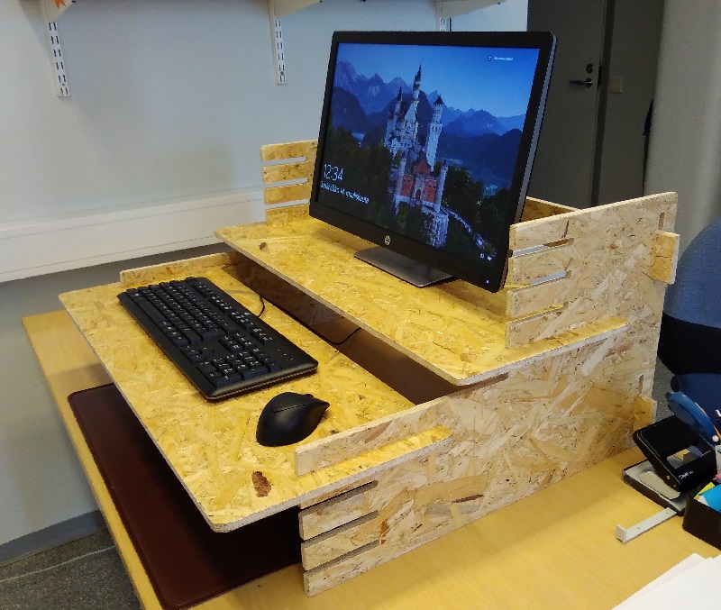
Design needs more level options, but for first go, it was fine.
Learnings
Before switching from model to cam in Fusion 360, disable sketch. It caused some issues later when picking heigths and countours.
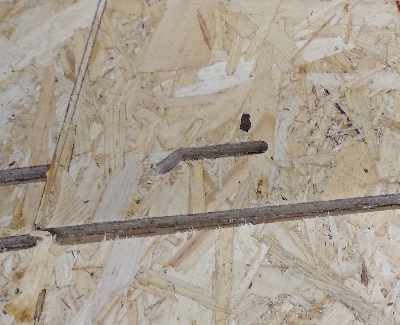
On CNC milling machine, make sure to fasten your material good. Even I had suction bed active, and board screwed from sides, it was still little up on the middle. Resulting that tabs were actually milled away and therefore that part ending loose and in failure.
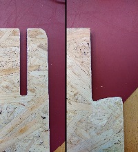
When sanding, be extra careful. I had 30mm wide part was snapped off by the sander, though it might have already been shattered somewhat, for material being what it was.
Group project
Group efforts can be found here.
Files
Fusion 360 designToolpath
support.stl
side.stl
level.stl