
Kati Pitkänen @ FAB LAB OULU · 2018
© 2018 Kati Pitkänen · Template by Bootstrapious

This work is licensed under a Creative Commons Attribution-NonCommercial-ShareAlike 4.0 International License.
Mechanical Design
Week 17 · [ 9.5.2018 - ]
- Actuate and automate your machine
- Document the group project and your individual contribution
It was interesting week to work on and see, if we managed to get our measuring machine run. We had the basic mechanism of the machine working in early phase, but in the end we faced several small problems, such as bad connections between the cables, which took way too much time to solve. However, the idea of the machine axes functions was realized.
During the week I worked on small details, design and laser cutted some small parts needed, assembled parts and finished hiding the cables and visual appearance of the machine. Moreover, we had a nice idea of 'plug-in' VCD adapter system to power our machine and a small give added value for the user by adding the bridge board on the side of the machine for asy access and powering the machine. To realize it, I re-designed and created a bridge board that adapts FTDI -cable to multi-drop network. However, unfortunately, we didn't manage to find appropriate VDC adapter to be attached our board.
MACHINE DESING: FAB KATARI
Our local instructor of the week was Yrjö Louhisalmi.
During the week, I documented the most important phases, testing, debugging, developing, and considerations.
The documentation of the Machine Design -project is here: THE MEASURING MACHINE: FAB KATARI
Electronics Designing
For running the machine, we are using four NEMA-17 stepper motors, and one gestalt node board for each of them. Together these four nodes form a multi-drop network, sharing a single set of communication wires which, and being controlled by RS-485 bus with a few additional signals. Fab Academy tutorial was a nice help to get started with this.
I learned, that to establish connectivity between nodes and a computer, and providing proper power, requires having several components: high and low voltage power supplies, an adaptor board (076-000A) with bias resistors and FTDI -cable. The adaptor board (bridge) adapts FTDI -cable to multi-drop network, which in our case is consisted of four gestalt -node boards, that share a single set of communication wires, and are controlled by RS-485 bus with a few additional signals.
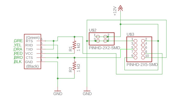
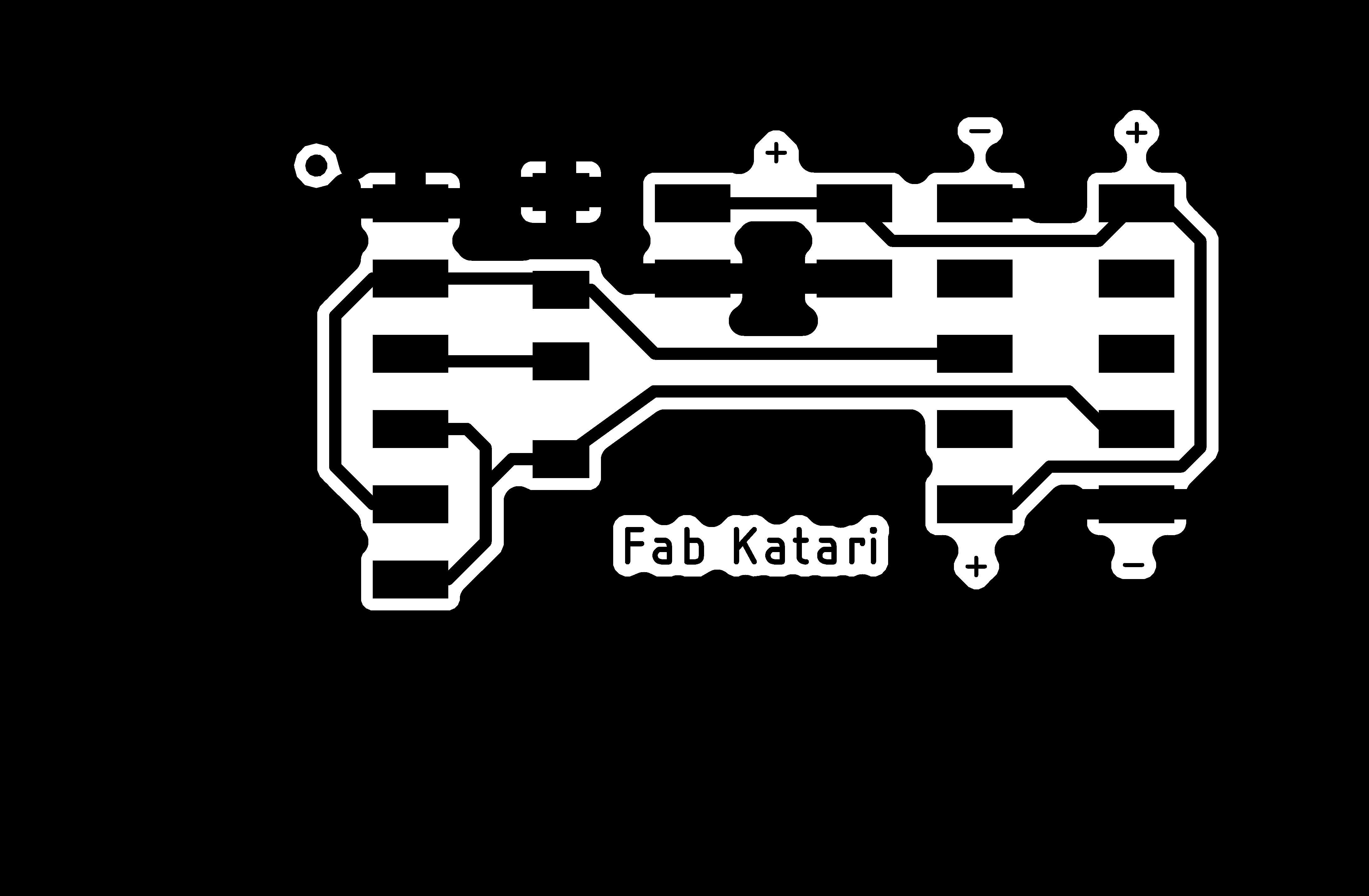
We considered, that it would have been nice to attach the bridge board on side of the machine for easy access. To make this, we aimed at adding a small additional value for user by modifying the bridge, and add a VDC plug-in adapter on top of if for powering the machine easily. To realize it, I re-designed and created a bridge board prepared for the adapter and also using fixed 1x6 pin header for FTDI:
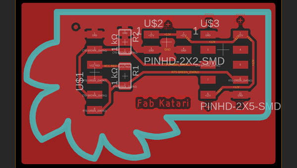
Here are the png pictures for milling. I designed some marks for easy reading, sush as marked the FTDI ground, power and ground of pin headers, as well as named th board but I didn't realize that the size of the texts were actually so small, that it can be hardly seen from the milled board. Next time, I will campare the results of this and my previous flower boards to make sure, that in case I want to add any text or figures they are big and clear enough.

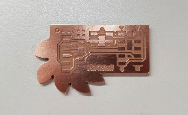
Milling worked fine. Drawing with 16 mils line width, and using V-shaped milling bit, Tool diameter 0.2 (mm) and Cut depth 0.08 (mm) gave me the result below. Also soldering was nice, I really enjoy that work stage.
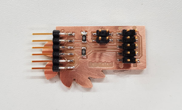
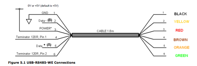
However, I didn't go far enough to find, that it is not the original TTL-232R-5V FTDI-cable that we are going to use to use, insted we will need a USB-RS485 converter cable. This is why I changed the order of the FTDI-cable to fit it straight through to commercial cable, but right after I found that it was unnecessary. Because we didn't have more USB-RS485 -cables in the Fab Lab, and we didn't manage to add a VDC adaptor on our new board, we decided to not break the working cable+board combination from the previous year group work but to continue using that one.
A bridge board that adapts USB-RS485 cable to Fabnet:
Finishing
For attaching the button sensor to the Z-axis, I measured the positions of the screws on the sensor head component, that Ari had 3D designed and -printed, and added four holes for screws and two for power ang ground cables.
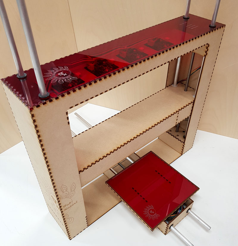
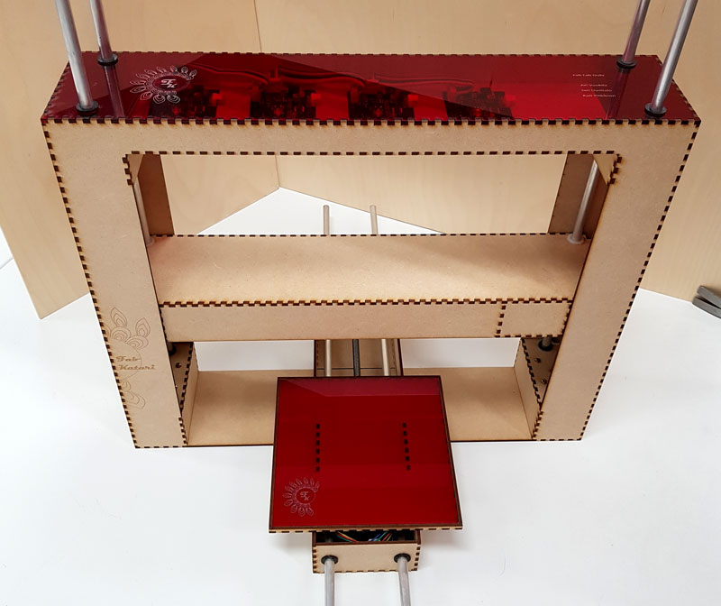
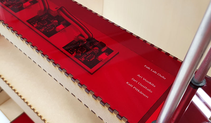
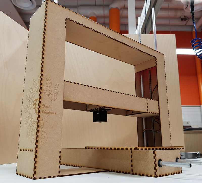
For finishing the visual appearance of the machine, I fixed the wire lenghts, moved the node boards on to their final location on top pf the machine, and hide the cables inside the axes.
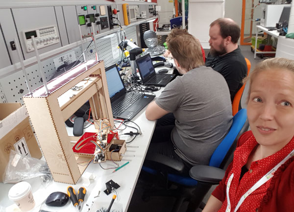
Here, the Fab Katari Team is working on finishing the machine:
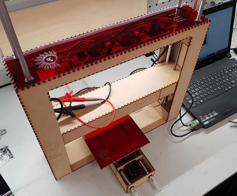
The visual appearance of the machine after the second week:
The documentation of the project is done by me: THE MEASURING MACHINE: FAB KATARI
Here are the files I produced during this mechanical design week:
- The traces of the bridge board for milling in png format
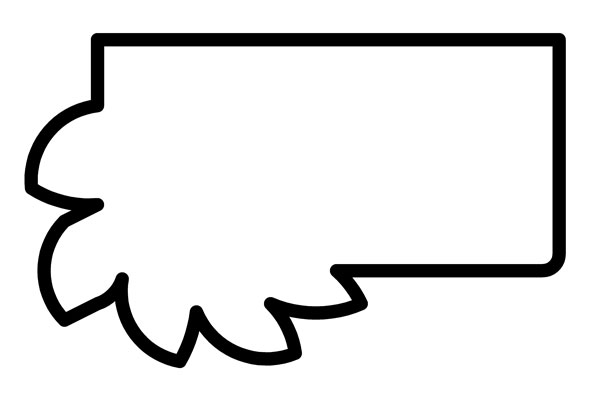
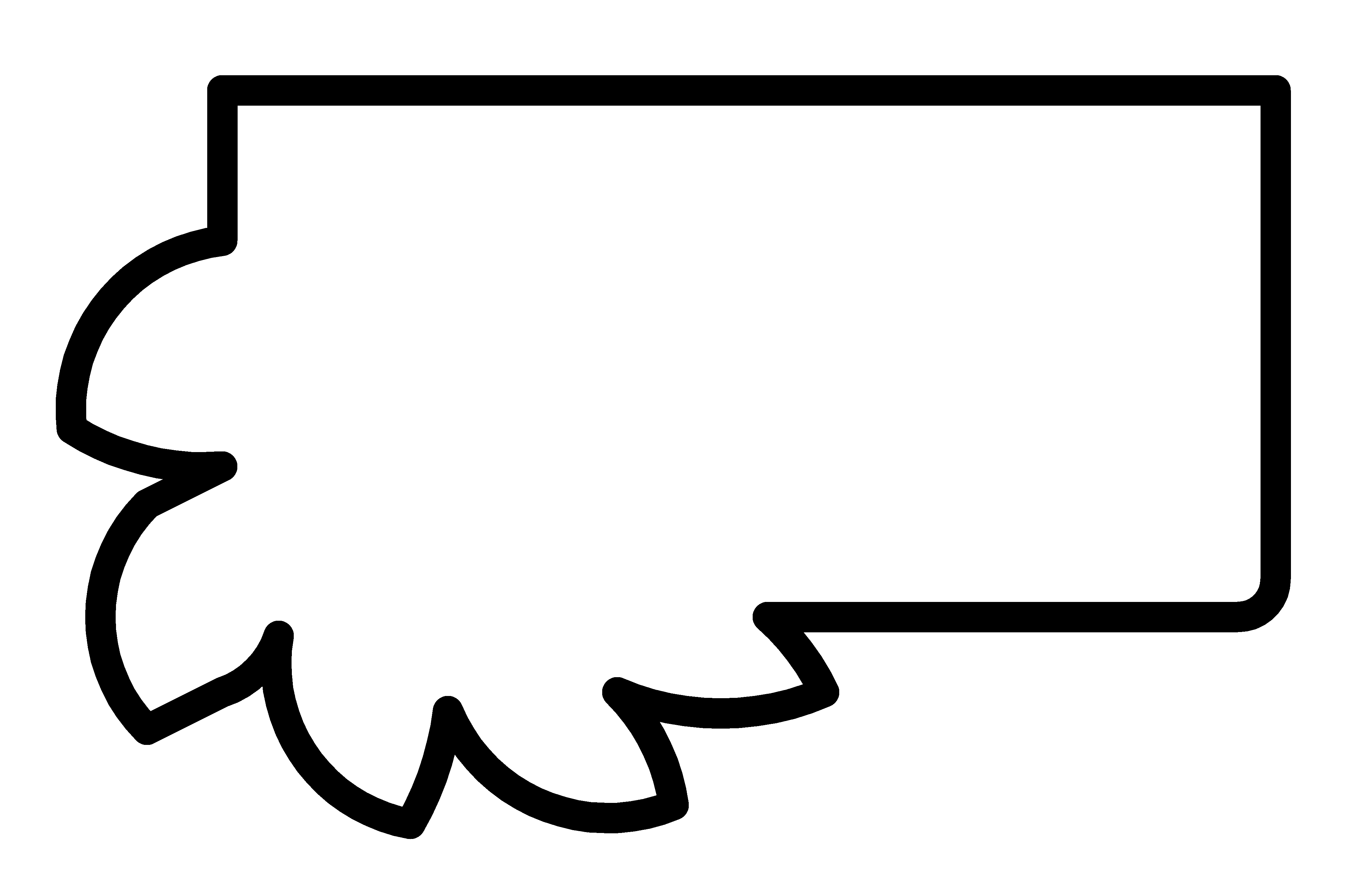
- The outline of the bridge board for milling in png format
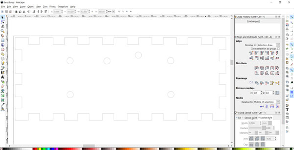
- The piece of a sledge for attaching the sensor head on the Z-axis in svg format
- The piece of a sledge for attaching the sensor head on the Z-axis in pdf format