
Kati Pitkänen @ FAB LAB OULU · 2018
© 2018 Kati Pitkänen · Template by Bootstrapious

This work is licensed under a Creative Commons Attribution-NonCommercial-ShareAlike 4.0 International License.
Wildcard Week: Water Jet Cutting
Week 18 · [ 16.5.2018 - ]
- Design and produce something with a digital fabrication process (incorporating computer-aided design and manufacturing) not covered in another assignment, documenting the requirements that your assignment meets, and including everything necessary to reproduce it. (Individual Project)
- Design and produce something with a digital fabrication process (incorporating computer-aided design and manufacturing) not covered in another assignment, documenting the requirements that your assignment meets, and including everything necessary to reproduce it. (Individual Project)
- Characterize the water jet cutter and build an understanding how the machine functions
- Show how I made my project, including describing the problems and how I fixed them
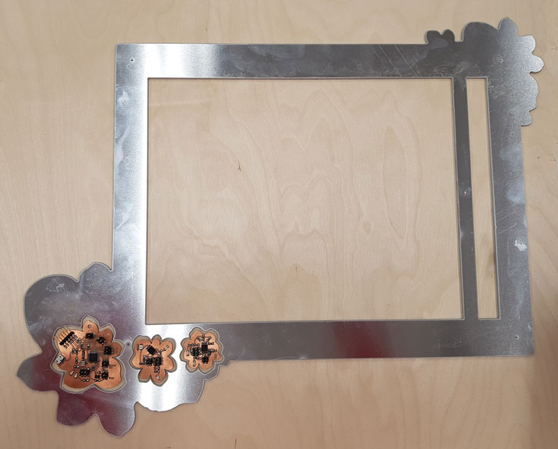
- Fabricate the aluminium frame for the final project
In this Wildcard Week I experienced the process of water jet cutting, which was my first time to experience and see this machine working. For some weeks I had considered that I would like to make something with a metal milling machine. I thought, that this would be a good chance to make the frame for my final project. However, the milling area of the machine was too small for the size of my frame.
Then I heard that we could have a possibility to use a water jet cutter on the Machineshop at the University of Oulu, which supports the operation of Fab Lab Oulu in such processes, where there is a need of some bigger or sturdier machines. This was fantastic, because I managed to make the frame I had dreamed about out on lightweight aluminium. Many thanks to the Machineshop Manager Kasperi Hahtonen for his valuable time and kind help on going through the process of water jet cutting, as well as our local instructor of the wildcard week Jari Pakarinen, who was very helpful and supported the process since the beginning.
What is different compared to a laser cutter is, that a water jet cutter doesn't have focus as a laser cutter has, but it will cut all the way through - also the material bed, which has to be renewed every now and then. Moreover, where a laser cutter cuts in the middle of the vector line, a water jet cutter cuts either along the inner or the outer edge of the vector line. When using appropriatd CAD -programs for designing, this should not be an issue. However, with less appropriate programs, which are not intended in such precise cutting and the line thickness used for drawing can vary, it can result unexpected outcome.
ABRASIVE WATER JET CUTTING
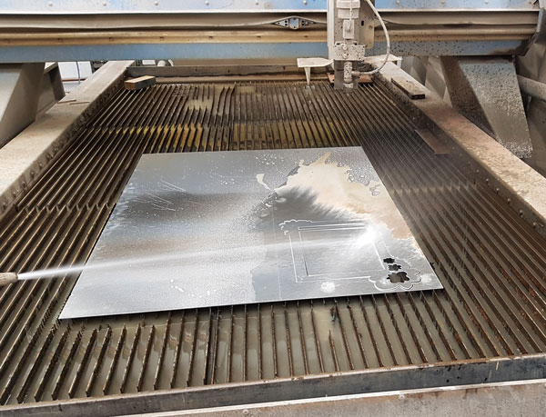
I used Aliko abrasive water jet cutter (3000 x 1500 mm) for cutting. Using a water jet cutter, even complex geometry and high-precision requirements are made very fast and easy. Because the cut method is "cold" processing method the piece will not suffer any thermal effects such as bending.
Water jet cutter functions so, that a jet of water is ejected from nozzles "at three times the speed of sound" (Aliko). Because of this, it is possible to cut almost any material without (noise,) dust or flue gases. Water jet cutting is at its best when cutting thick aluminium and refined steel parts, which with other cutting methods is not possible to cut economically and accurately. However, water jet cutting is suitable for all materials, for instance glas, thick engineering plastics, rubber sheets, waterproof plywood, stones and ceramic materials, and further also brass and copper, which can be challenging for a laser cutter (jetmasters).
For cutting metal and other harder materials, such as aluminum that I cut in my project, abrasive sand is mixed with the water in order to improve cutting power. In that process, water moves sand and gives it the pressure and speed to cut the material.
Cutting thickness ("tool diameter") is around 1 mm, but it varies depending on the service life of the nozzle, because a diameter of the nozzle will widen in use. Cutting precision is +/- 10 um. The parameters that a user can control are speed, pressure, and the amount of the sand used. When these parameters are set according to the thickness of the material, it is possibe to cut very precise holes and openings even on very thick material.
Designing an aluminium frame
In the beginning of this week, first of all, I designed a structure of my final project LED screen utilizing Inkscape because of its Tabbed Box -extension.
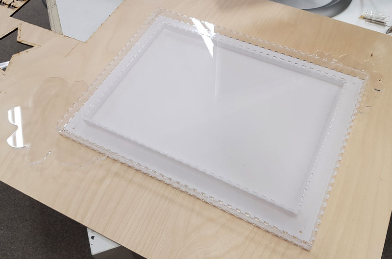
I was going to have separated frame on top of the acrylic structure so, that the outer edges of the top acrylic part and an aluminium part above it would be identical. This is why I had to finish the structure first to be able to design the front frame itself after that.
I used Inkscape Extensions > Laser Tools > Tabbed Box Maker for designing the LED screen structure. Once I had designed the structure (after several iterations and prototypes documented on my Final project -page), I utilized that design for finishing the design of the front frame.
Basically, the top frame is similar to the middle frame but the difference is, that the front frame does not have the tab holes for assembling the frame structure, instead, it will be attached to the acrylic component using bolts and nuts. For this, I removed the tab holes by activating and deleting their vector lines, and left only the holes for bolts.
Then, I saved the file in dxf format.
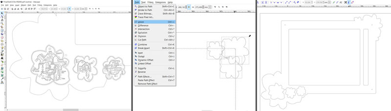
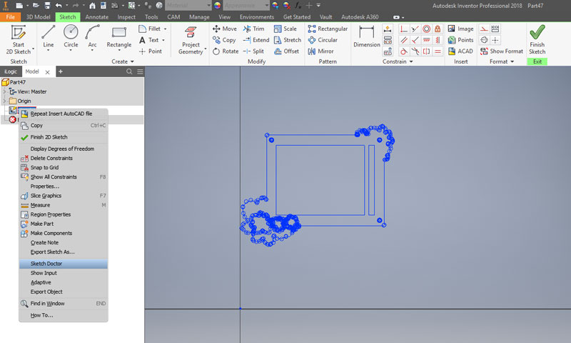
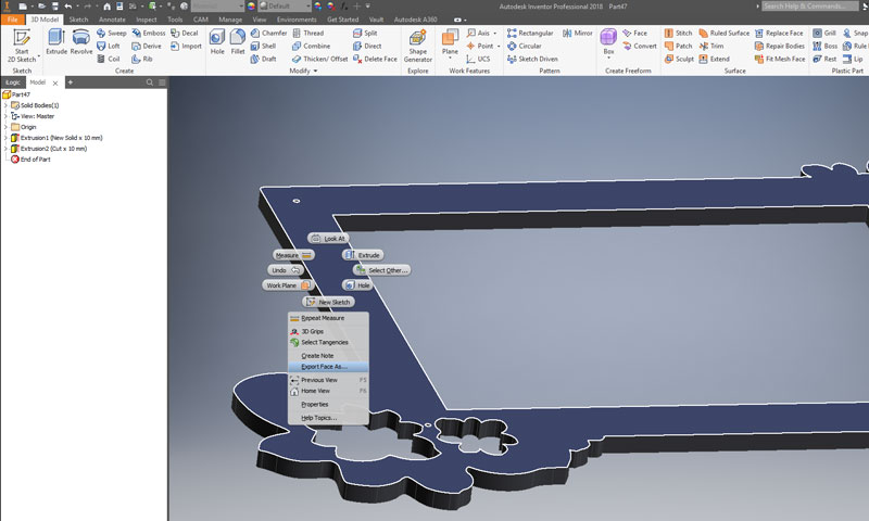
Since I did my design with Inkscape, which really is not a CAD program, I faced the problem in creating the cutting file. This was because the vector lines created in Inkscape were not actually connected when the design file was opened in CAD program. First, the design was tried to fix right-clicking above the Sketch on the left history bar and using Autodesk Inventor > Sketch Doctor, and then Export Face as: AutoCAD 2010 DXF, but for some reason Inventor did not make the third hole for flower shaped PCB.
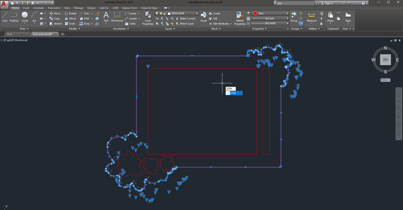
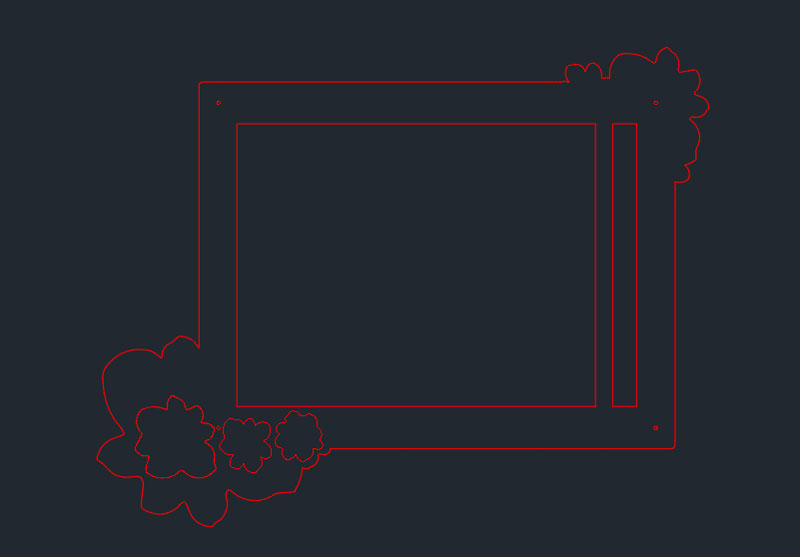
Then, I was adviced to fix the file just with Autodesk AutoCAD. I opened the frame design file made in Inkscape. Then, all vectors were selected in small groups and checked carefully to notice the lines that were not connected but actually had some tiny unconnected space between the vectors. Moreover, the circles were not circles at all, but consisted of four arcs, when opened the dxf file in AutoCAD. These errors were fixed manually by selecting a piece of vector paths, finding and connecting unconnected ends, and joining them together by typing on the command line JOIN. Moreover, the fixed parts were grouped by typing on the command line GROUP.
Now, the design was ready for saving it by Open > Save As > Other Formats: AutoCAD 2010/LT2010 DXF (*.dxf).
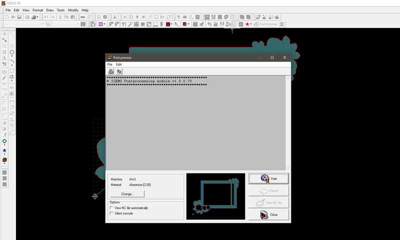
Generating a G-code with IGEMS R9
Finally, the dxf file was opened and the toolpath was generated succesfully using IGEMS R9, which is a modern CAD / CAM software designed for waterjet cutting machines.
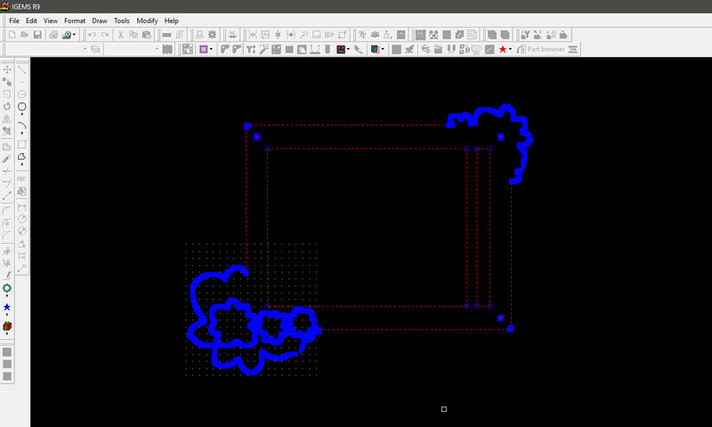
First, open the file by File > Import Drawing and drag the bottom left corner of the design in the dotted area.
From the top bar, navigate into Modify > Join and select everything of the design.
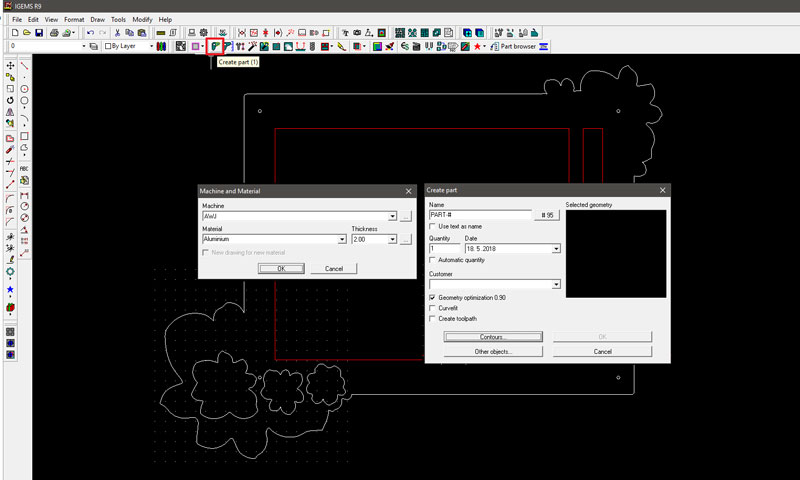
Then, click on the Create Part icon, and define the settings:
- AWJ // Water Jet Cutting
- Material // Aluminium
- Thickness // 2 mm, and hit OK
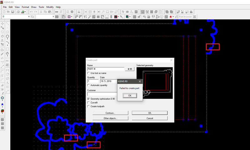
In the next window, click Contours, select every line on the desing, and right-click mouse above the black area to Enter and get back to the window, and hit OK. At this point, the software noted that it Failed to create part and I noticed that some of the vector lines were not connected. They were fixed using Autodesk AutoCAD as described above.
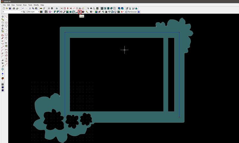
After fixing the unconnected vector lines and repeating the steps till here, I clicked on the Holes icon and select the tiny holes on the design by dragging and hit OK.
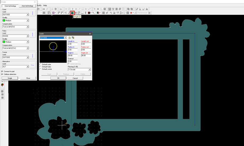
Now, click on the Single icon, and select on the design the lines that will be cut in such order you want them to be cut: first the details and small parts and in the end the outer edge line to cut the piece off the material sheet. The settings under this menu was not changed, so I continued by choosing OK.
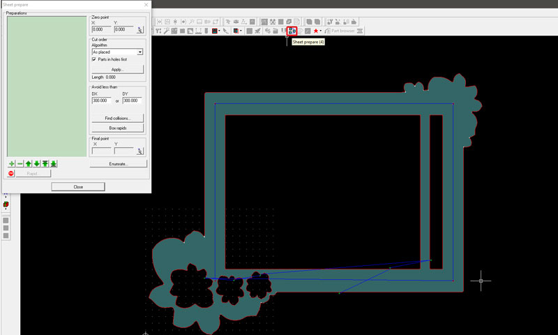
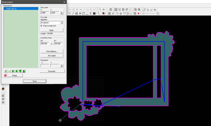
Furthermore, click on the Sheet prepare icon and select everything on the design by dragging and hit OK.
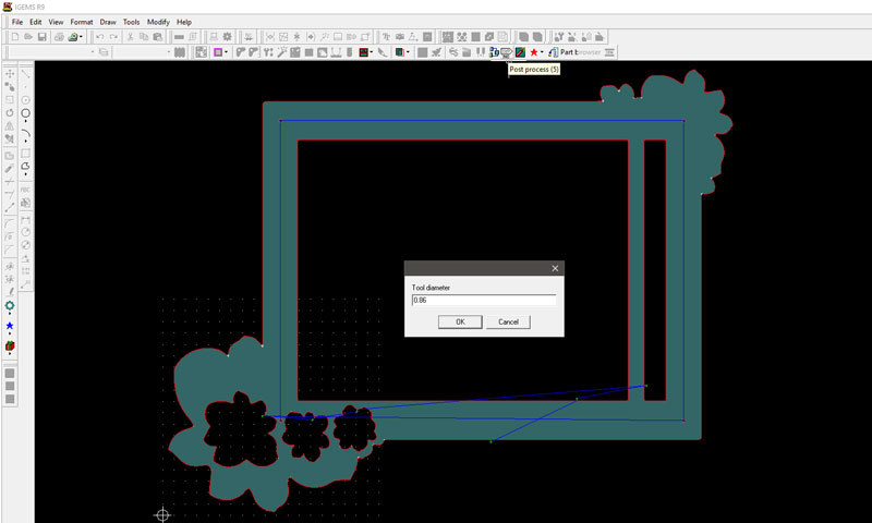
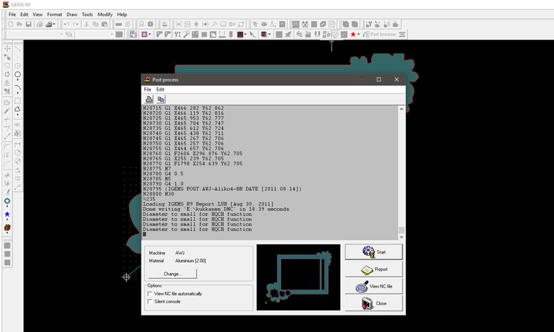
Finally, click on the Post Process icon and define Tool diameter, this time 0,86 mm and hit OK. This time means, that the tool was quite new so its diameter was 0,86, but since it is a wear part the diameter will widen in use. Now, the software will generate the NC file for cutting.
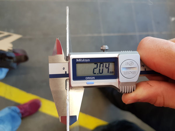
Preparing the machine
To begin, I checked the thickness of the aluminium, which was quite accurate, 2,04 mm.
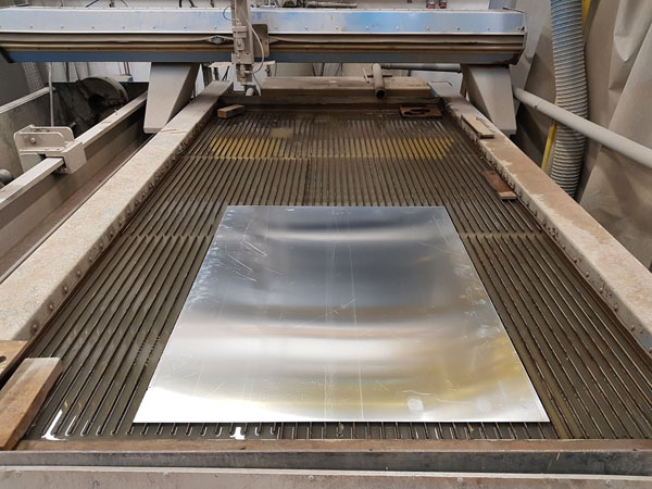
Then, the material to be cut was placed on the machine steel bed so, that it was in line with the frame lines. This steel bed is a wear part, which will be cut alongside of the actual material to be cut as well, so it has to be replaced every now and then. This is the difference compared to a laser cutter, which has fixed focus and cutting point, and it will cut only at this defined focus height, which means that a laser cutter might burn the material if the focus is set too low, but then, it will not even cut through the material incase the focus is set too high.
Note: The sand that is used has to be round instead of oblong, because the latter one will stop up the nozzle. This is why, especially when ordering some new sand, it is important to check the form of the sand.
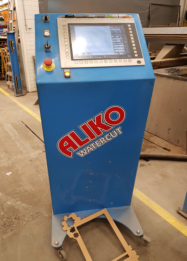
Operating the machine
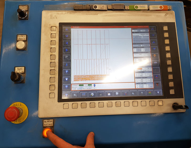
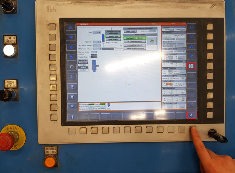
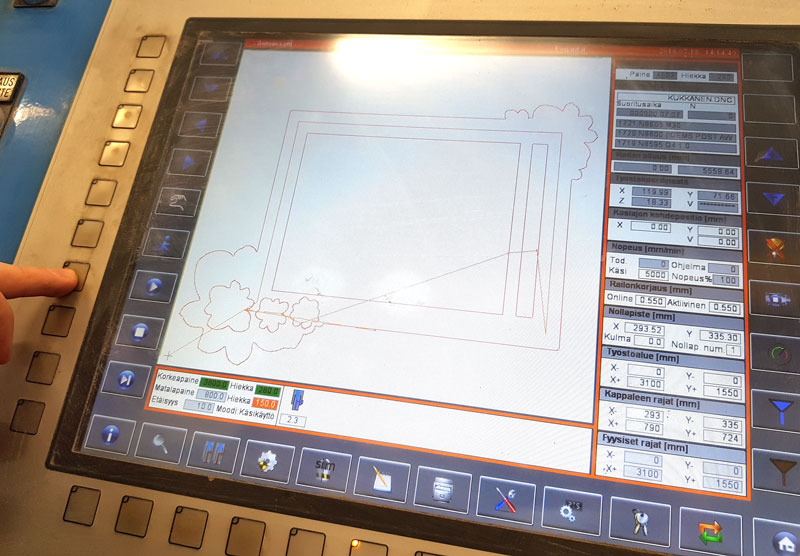
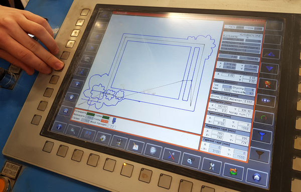
Here is the operating panel of the water jet cutter:
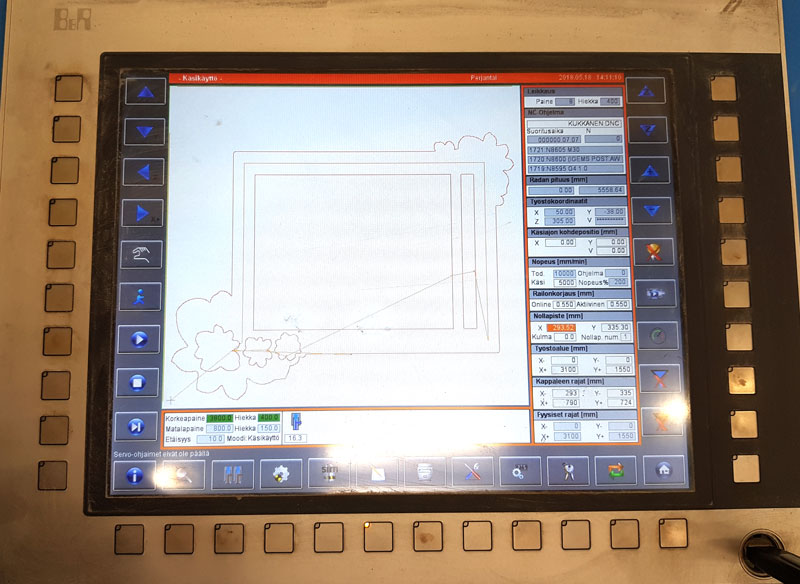
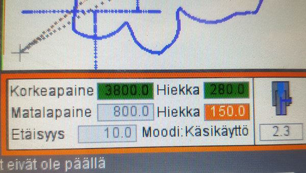
This is how the UI in the operating panel looks like:
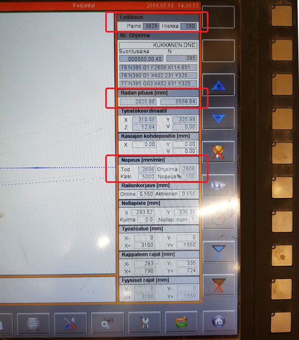
- SPEED // 2600 mm/ min
- PRESSURE // 3800 bar
- SAND // 280 g/ min
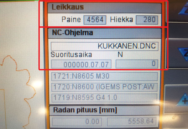
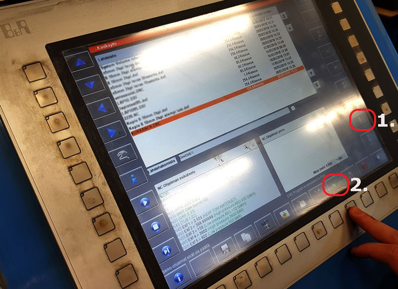
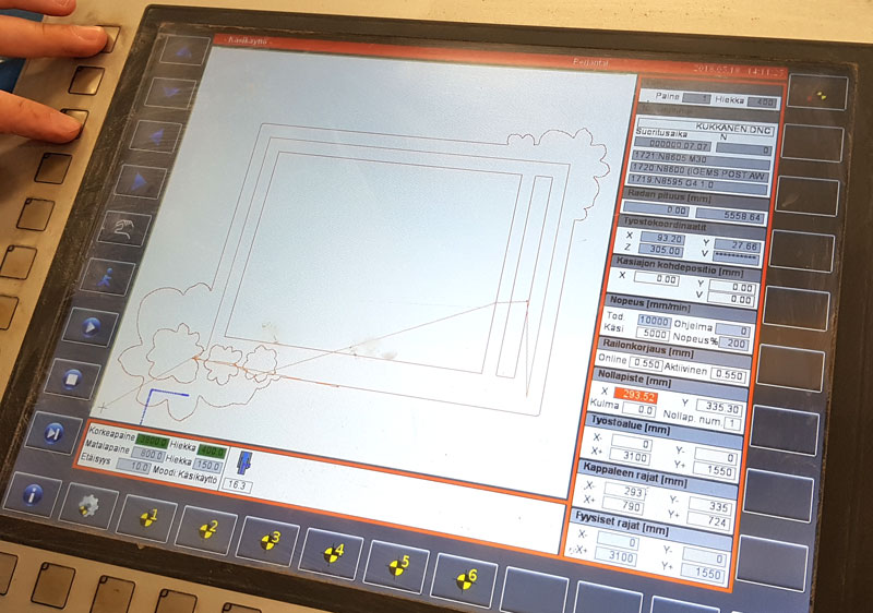
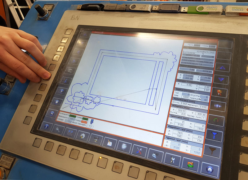
- 1) Open the g-code file on the operating panel UI // NC-program can be previewed on the bottom left corner
- 2) Check that there is no-one on the machine area and check the safety system with light curtain
- VALOVERHO KUITTAUS (The safety system with light curtain) -light turns from ON to OFF
- OHJAUSJÄNNITE (Reference Voltage) -light turns from OFF to ON
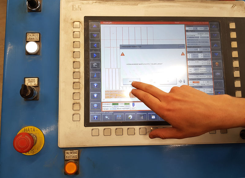
- 3) Check the error message regarding the Reference Voltage and hit KYLLÄ (Yes) to continue
- This message complains about the safety system with light curtain which was activated before checking it off
- 4) Start the servo controls // Press PLAY twice.
- 5) Adjust the zero (origin) with the help of laser pointer // Use the four arrows on the top left corner to do that
- Cutting area X: 3 m, Y: 1,5m
- Check the zero by pressing the "Wheel" -button twice
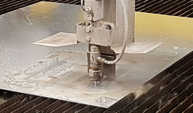
- 6) Measure the thickness of the material using the automated measuring head of the water jet cutter.
- 7) Turn on the water pump
- Notice, that there will be a bigger pressure on the pump than set, but for cutting the pump will limit the pressure to the value calculated in the g-code based on the material and material thickness
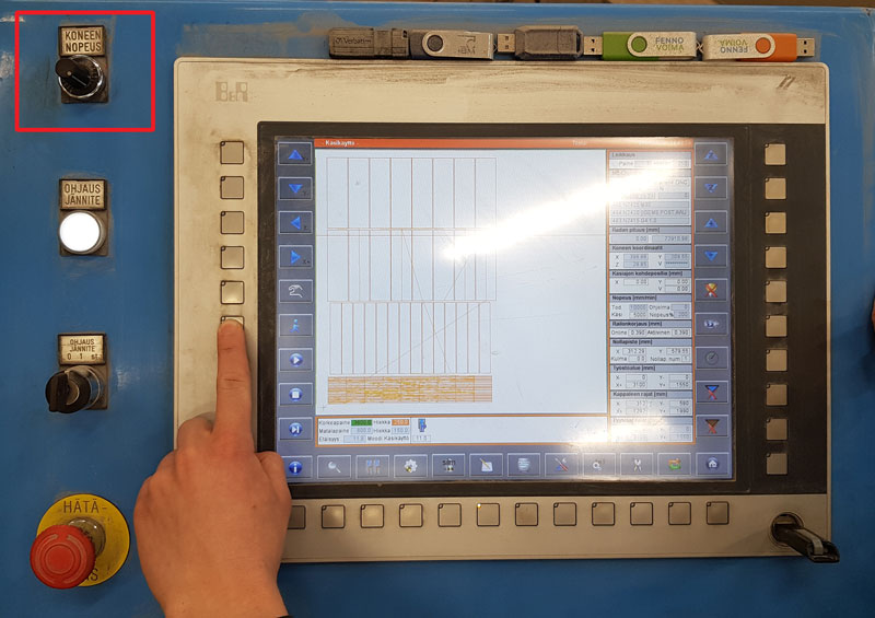
- 8) Adjust the speed of the machine (KONEEN NOPEUS) // 100 %
- 9) Activate the automatic mode // This will void/ prevent the manual mode
- 10) Press PLAY to start cutting
- The initial design of the Flower frame in svg format
- The fixed design of the Flower frame in dxf format
- G-code of the Flower frame in dnc format
There has to be more power on the pump than it will use, and then the pump limits the power to the parameter that was set by the user.
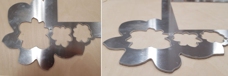
After the object is cut, rince the object and remove it and rest of the material from the cutting area.
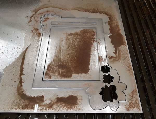
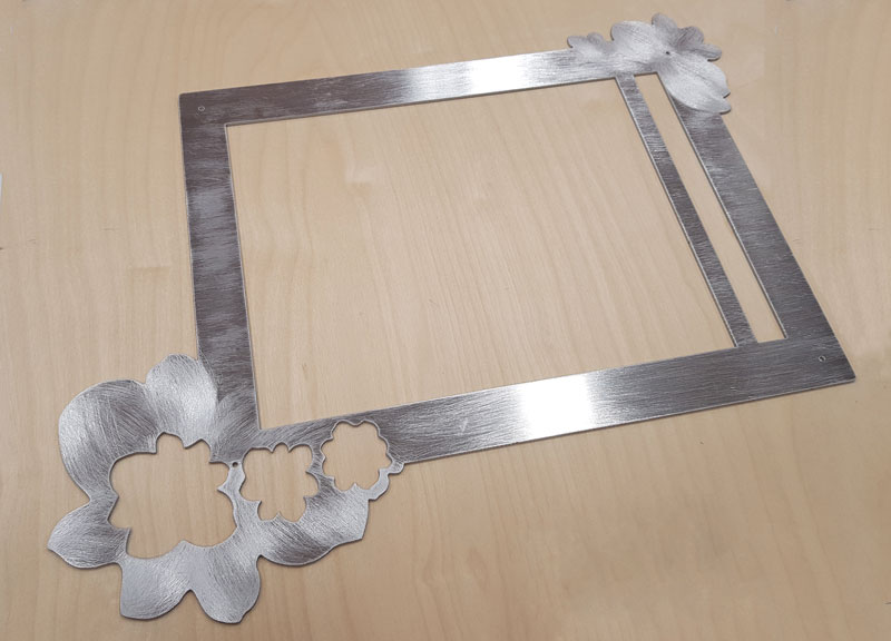
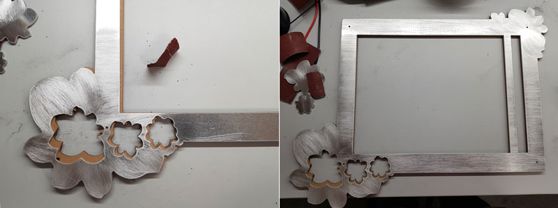
The cut result was almost perferct. What the water jet cutter did not cut out as designed was the hole for bolts. I had designed them to be of diameter 3 mm. However, the holes were only shot through but not cut as a circles. I need to increase the size of the holes manually afterward.
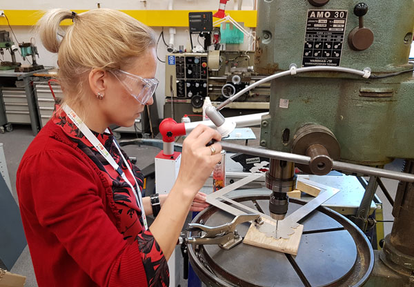
Finishing the frame
Drilling the holes bigger. Never think how the milling bit shoud rotate, bacause the cables can be connected different ways. Instead, always check what is the actual rotating direction, when you turn on the machine.
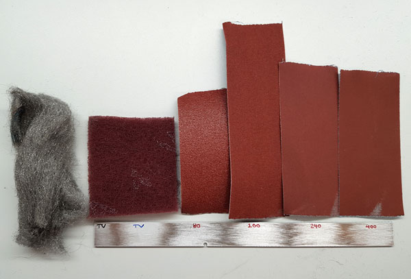
Surface sanding tests. I wanted the surface look like brushed steel. I tried to sand the surface using two different metal wools, and sandpapers of four different grit sizes: 80, 100, 200, and 400. I liked the most rough result the best.
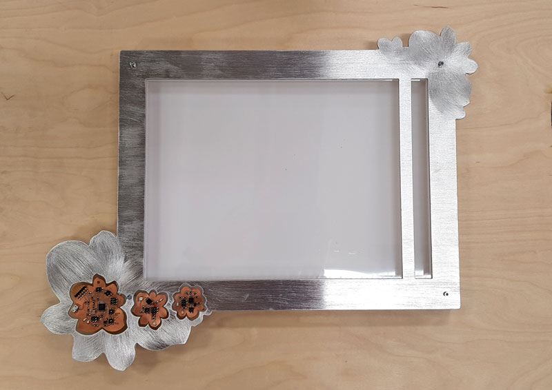
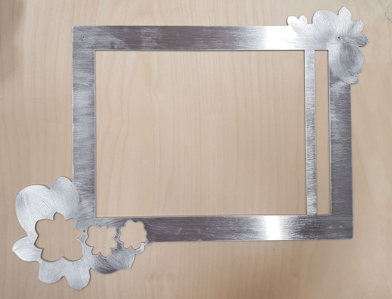
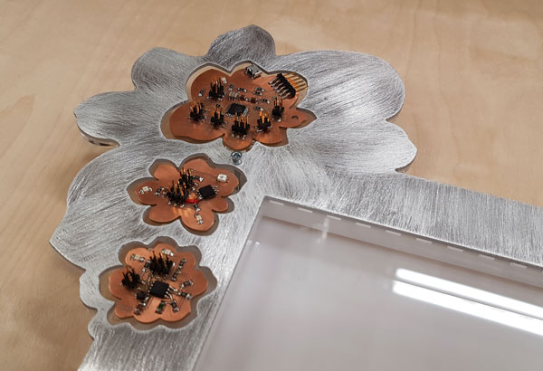
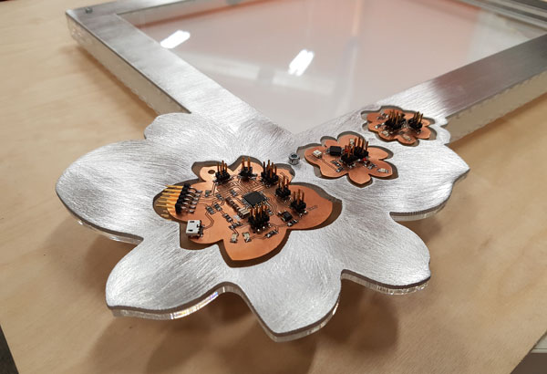
So, I sanded the surface using a sandpaper of grit size 80. I sanded most of the frame horizontally, but the details - surrounding of the holes for Flower -PCBs - I wanted to sand to the form of a flower as well. Lastly, the frame was varnished with Maston Transparent lacquer to prevent the sanded surface from oxidation.
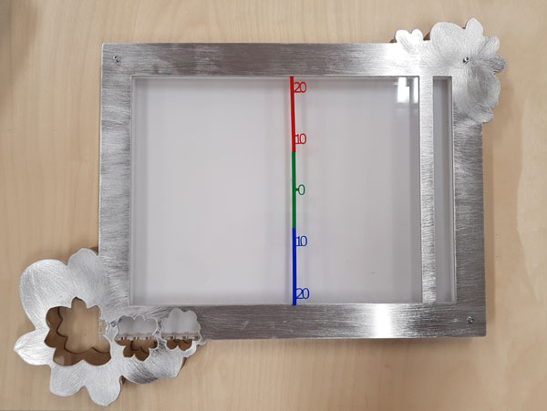
This is the aluminium frame that is going to be he top frame of my Final Project - The temperature meter LED screen.
Here are the files of my Wildcard Week: