
Kati Pitkänen @ FAB LAB OULU · 2018
© 2018 Kati Pitkänen · Template by Bootstrapious

This work is licensed under a Creative Commons Attribution-NonCommercial-ShareAlike 4.0 International License.
Embedded Programming
Week 9 · [ 14.3.2018 - ]
- Read a microcontroller data sheet. (Individual Project)
- Program your board to do something, with as many different programming languages and programming environments as possible. (Individual Project)
- Optionally, experiment with other architectures.
- Compare the performance and development workflows for other architectures. (Group Project)
This week I have tried to get an overview of the 286 pages content of ATtiny44A microcontroller datasheet. Moreover, I have programmed my Heart-shaped Echo Hello-World board by using Atmel Studio 7.0 and Arduino 1.6.4. In the group work we experiment with and tried to program also Atmel XMEGA-E5 Xplained, Raspberry Pi 3, and Nucleo-F401RE architectures.
I started work on the assignements exploring Atmel Studio. I had not used nor Atmel Studio neither C -language earlier so, I needed to understand how the they operate. I got started quite nice thanks to our local instructor Juha-Pekka Mäkelä and additionally, with the help of Eino Antikainen and Jari Pakarinen whose documentation from the previous year I found very helpful.
Instead, I was a bit familiar with Arduino already so, it was easier to find the basic code and modify it to fit my purpose in that one. At the same time, I learnt some main differences between Atmel Studio and Arduino, such as requirement to add some more rows defining the ports or functions in the code in Atmel Studio, whereas in Arduino they are ready-built inside the program making programming way more simpler. However, I learned also, that programming by C makes the code way quicker since what is ready-built inside the Arduino increases background processes, when Arduino has to check more things every time when performing the code.
Once again, the greatest learning happened while writing this documentation and trying to understand the unfamiliar but important phases of the process. For example, earlier, I had found out what will some code make but this week I figured out also how the command line is composed (e.g. for setting up Fuses).
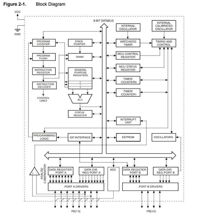
Unpacking the ATtiny44A Datasheet
I started learning the overview of ATtiny44A microcontroller and its datasheet by checking the microcontroller's features in the head page, where I got an understanding that ATtiny44A is a:
- High Performance, Low Power AVR® 8-bit Microcontroller having
- Advanced RISC Architecture, in which most of the 120 instructions are executed in 'Single Clock Cycle Execution'.
- 32 x 8 General Purpose Working Registers
- High Endurance, Non-volatile Memory Segments
- 2K/4K/8K Bytes of In-System, Self-programmable Flash Program Memory
- One 8-bit and One 16-bit Timer/Counter with Two PWM Channels, Each
- 10-bit ADC
- Internal and External Interrupt Sources
- Twelve Programmable I/O Ports
Moreover, the microcontroller
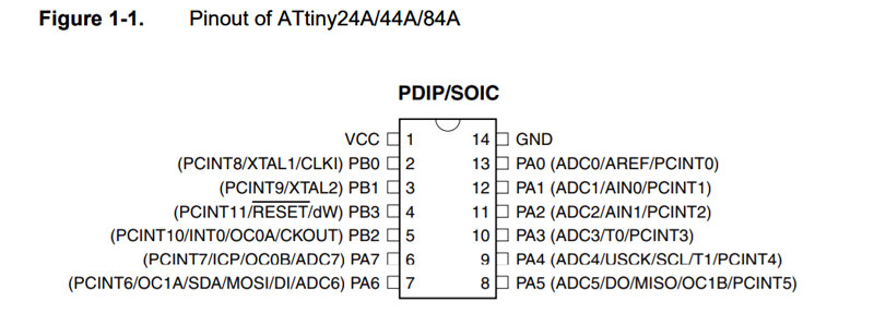
The ATtiny44A version 14-pin SOIC has following Pin Configurations:
- VCC // Supply voltage
- GND // Ground
- 8-bit port (PORTA) named PA7-PA0
- bi-directional I/O port with internal pull-up resistors (selected for each bit)
- 4-pin port (PORTB) named PB0-PB3
- bi-directional I/O port with internal pull-up resistors (selected for each bit)
- The direction of a pin is defined by registers (Data Direction register):
- DDRA and
- DDRB
- Data is written to an OUTPUT pin using registers PORTA and PORTB.
For understanding the shorts in datasheet and C -languages bit operations I took a look at [TUT][C] Bit manipulation (AKA "Programming 101"), originally written by By Eric Weddington (Programming 101).
The operators work on bits meaning that when taking two 8 bit bytes, and combining them with any of these operators, I will get another 8-bit byte according to the operator's function, working on the individual bits inside the byte.
-
|// bit OR -
&// bit AND -
~// bit NOT (so it switches 0 --> 1 and 1 --> 0) -
^// bit EXLUSIVE OR (XOR) -
<<// bit LEFT SHIFT -
>>// bit RIGHT SHIFT
I found the datasheet contains information also for example about AVR CPU General Purpose Working Registers, which I might go back later on.
Preparing to program my Heart Shaped Echo Hello-World board
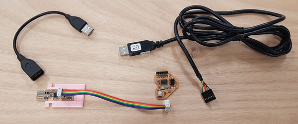
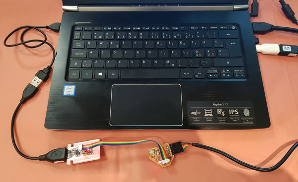
I started programming my Heart Shaped Echo Hello-World-board by collecting all the equipment needed:
- FabTinyISP programmer, ISP-programming cable and an extension cable for USB-port
- Echo Hello-World board and FTDI connector for USB-port.
- The FTDI cable is needed to power the Heart board because the programmer doesn't provide power for the programmable board.
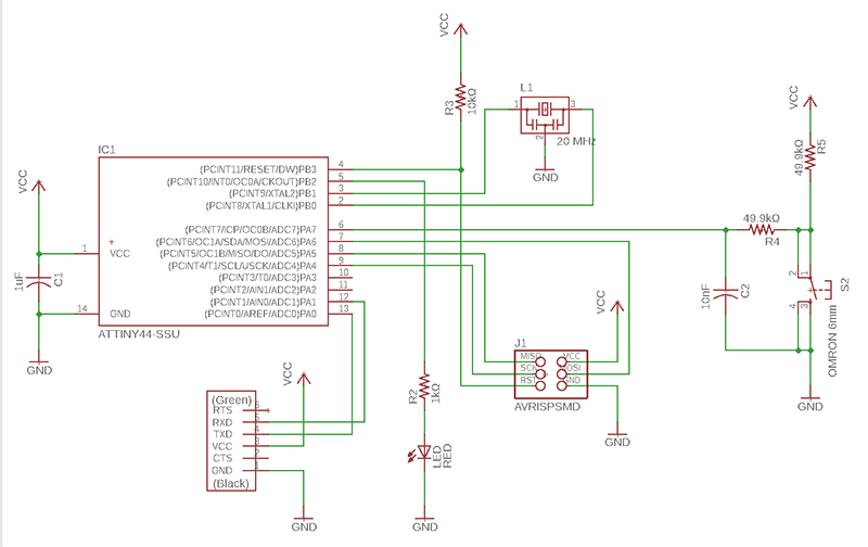
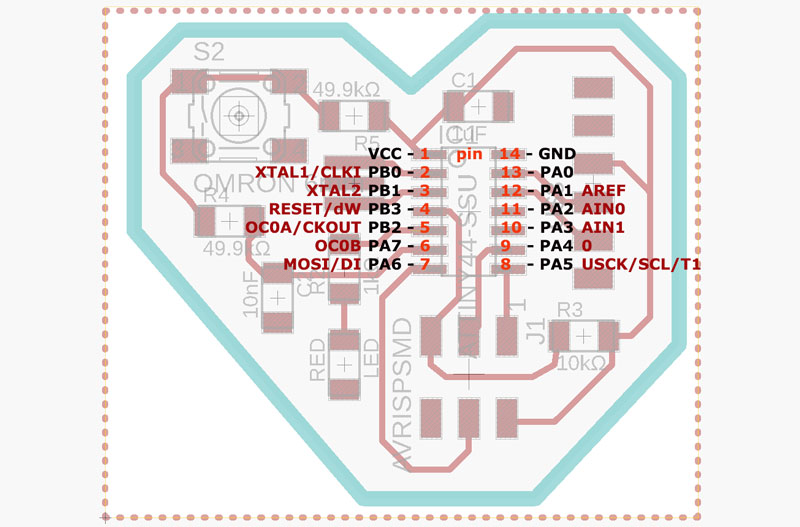
Also, I find the schematic and board layout of my Heart board for checking the microcontroller ports and pinouts I will use as inputs and outputs for code:
- Button // is connected to PA7 / pin 6 [in Arduino IDE the pin is 6]
- LED // is connected to PB2 / pin 5 [in Arduino IDE the pin is 8]
Programming Heart board using Atmel Studio 7.0
I started programming my Heart Shaped Echo Hello-World-board using Atmel Studio 7.0, which for I downloaded and ran the installer.
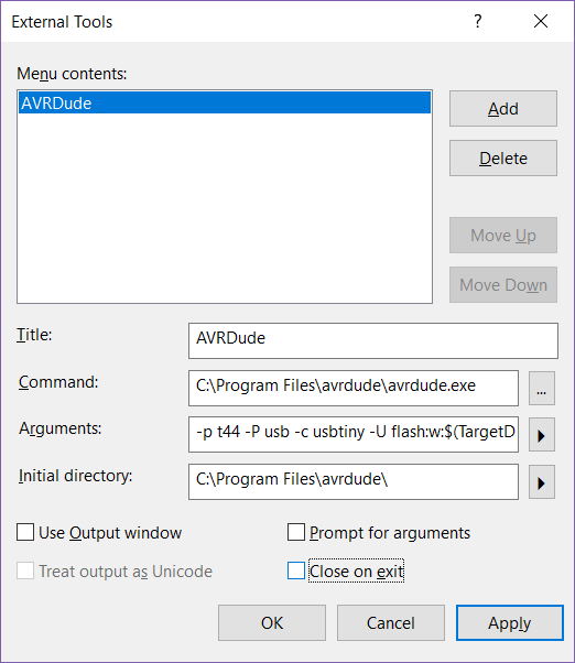
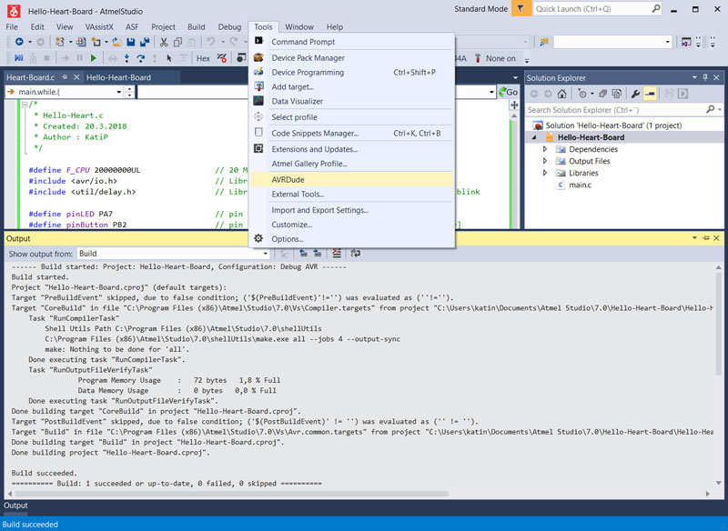
I opened the software, and added AVRDude tool, which will automatically locate avrdude.exe and program the board straight through from the location of built .hex -file, by navigating in the top bar to Tools > External Tools:
- In Menu contents: click Add for adding a new tool, and fill in:
- Title // AVRDude
- Command // [Locate your avrdude.exe -file]
- Arguments // [-p t44 -P usb -c usbtiny -U flash:w:$(TargetDir)$(TargetName).hex:i]
- Type the command
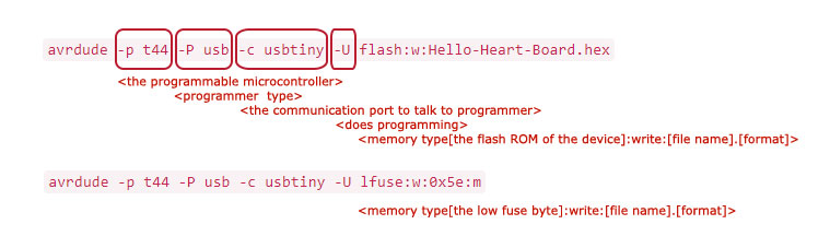
-p t44 -P usb -c usbtiny -U flash:w:where- -p t44 // part number tells the programmable microcontroller [where t44 is short for ATtiny44]
- -P usb // defines avrdude the communication port to use to talk to the programmer
- -c usbtiny // specifies the programmer type
- -U flash:w: // tells avrdude how to put data onto the chip and does programming; in this case, 'w' refers writing to 'flash' memory
- and click the arrow next to the row and select Target Directory and Target Name.
- Type the command
- Initial directory // [Locate your avrdude.exe -folder]
- Unselect Close on exit
- Press Apply and OK
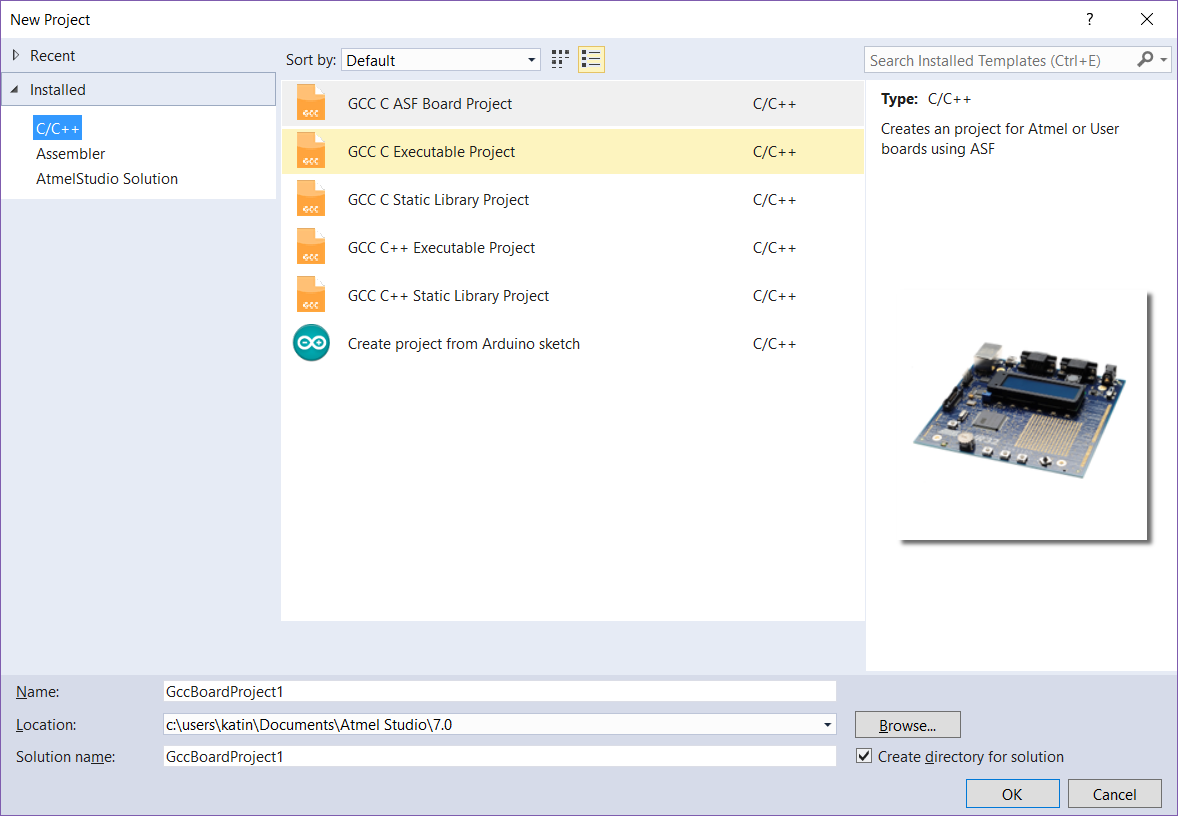
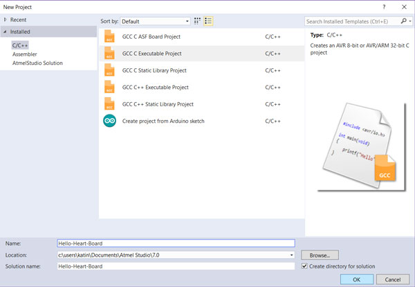
Next, I created a new project by navigating in the top bar to File > New > Project.
- From 'Installed' -tab I selected type C/C++ and GCC C Executable Project for creating an AVR 8-bit (or AVR/ARM 32-bit) C project and Name it.
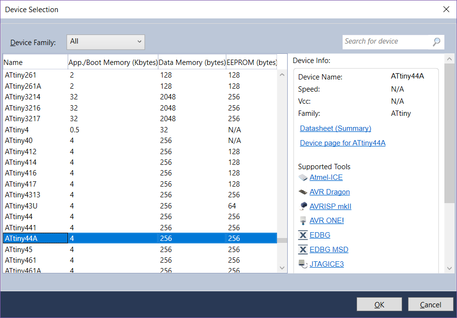
- Atmel Studio created me a new project, where I then did Device Selection // ATtiny44A
- Note, that you can find the device quickly by starting to type the name of it in the upper right corner "Search for device".
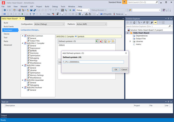
I defined crystal frequency by navigating in the top bar to Project > [Project] Properties > Toolchain > Symbols and:
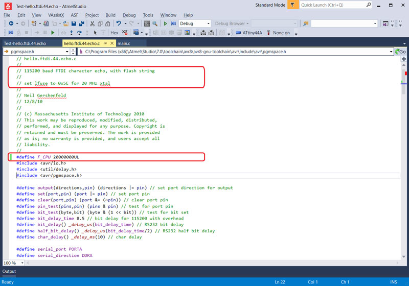
- Add Defined symbols // "F_CPU=20000000UL" (20 MHz)
- (Must be defined also right at the beginning of the code.)
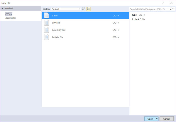
I created a new file to Hello-Heart-Board -project folder by navigating in the top bar to File > New > File and saved it as 'Heart-Board.c' by navigating in the top bar to File > Save CFile3.c As > [Name the file] Save
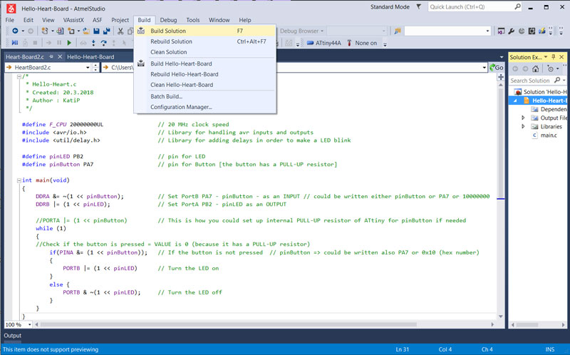
Then, I wrote a code for my Heart-Board.c -file with the help of our local instructor Antti, and other local instructors' Jari and Iván documentations from the previous year, and saved changes by pressing the Save symbol in the top bar. Writing code in C -language:
/* * Hello-Heart.c * Created: 20.3.2018 * Author : KatiP */ #define F_CPU 20000000UL // 20 MHz clock speed #include// Library for handling avr inputs and outputs #include // Library for adding delays in order to make a LED blink #define pinLED PB2 // pin for LED #define pinButton PA7 // pin for Button [the button has a PULL-UP resistor] int main(void) { DDRA &= ~(1 << pinButton); // Set PortB PA7 - pinButton - as an INPUT // could be written either pinButton or PA7 or 10000000 DDRB |= (1 << pinLED); // Set PortA PB2 - pinLED as an OUTPUT //PORTA |= (1 << pinButton) // This is how I can set up internal PULL-UP resistor of ATtiny for pinButton if needed while (1) { //Check if the button is pressed = VALUE is 0 (because it has a PULL-UP resistor) if(PINA &= (1 << pinButton)); // If the button is not pressed // pinButton => could be written also PA7 or 0x10 (hex number) { PORTB |= (1 << pinLED) // Turn the LED on } else { PORTB & ~(1 << pinLED); // Turn the LED off } } }
I created a .hex -code by navigating in the top bar Build > Build Solution.
Then, I connected to my computer's two USB-ports my programmer by extension cable and the Heart board by FTDI -cable.
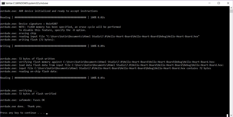
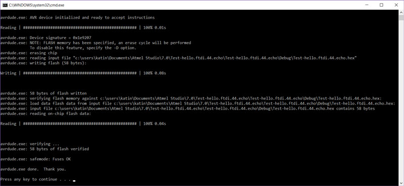
I programmed my Heart board using the created Heart-Board.hex -code by navigating in the top bar Tools > AVRDude.
The process and feedback of avrdude:
Another option to do programming is to open a command window in the folder where the .hex -file is located. Atmel Studio will save the .hex -file into the
Debug -folder inside the project -folder [C:\...\Atmel Studio\7.0\Hello-Heart-Board\Hello-Heart-Board\Debug] where I could navigate, and
start Git Bash or some other command window, and make avrdude to program the Heart board by the command:
avrdude -p t44 -P usb -c usbtiny -U flash:w:Hello-Heart-Board.hex .
Thus, AVRDUDE is a command line program, where the commands above actually mean:
I utilized Ladyada's AVR Tutorial and another
AVRDUDE tutorial generated by Joerg Wunsch to learn the basics.
The list of shortcuts and operations avrdude can do can be seen by opening a command window and typing avrdude .
Further, I tried to program Neil's hello.ftdi.44.echo.c to my board but I
failed continuously. I started a new project, defined F_CPU 20000000UL at the beginning of the code, built solution, created AVRDude and did fuses, as told below,
but didn't succeed in programming. When my board was programmed using the same file with another computer it worked just fine, and I got 'Putty' to reply on me by that program
also on my computer but, right after I tried to program it, it was silent again.
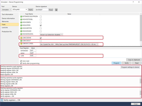
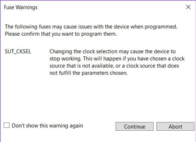
My first mistake was, that I hadn't done fuses. Fuse memory is a separate chunk of flash which has to be set separately from firmware updates. The fuses define for example the clock speed and crystal type, and they have to be set only once.
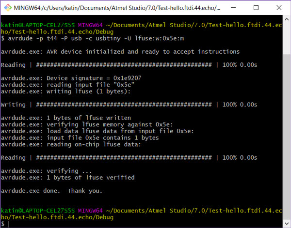
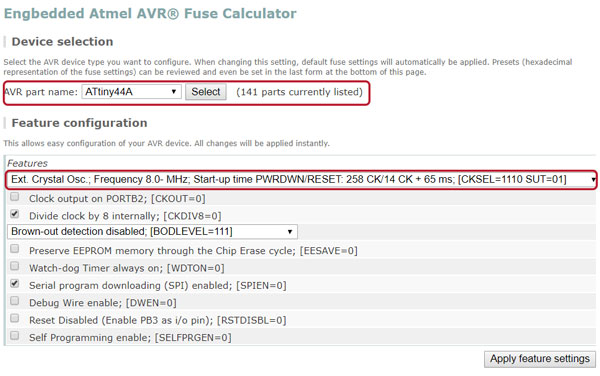
To setup fuses I utilized: Engbedded Atmel AVR® Fuse Calculator - which gave me a correct command to do by AVRDUDE arguments:
avrdude -p t44 -P usb -c usbtiny -U lfuse:w:0x5e:m
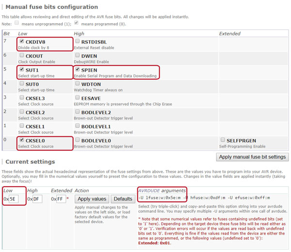
I didn't understand what does the following line obtained to help from Jari's site mean and why did I had to choose exactly that option so, I broke it to parts with a help of the datasheet:
Ext. Crystal Osc.; Frequency 8.0- MHz; Start-up time PWRDWN/RESET: 258 CK/14 CK + 65 ms; [CKSEL=1110 SUT=01]]
- External Crystal Oscillator; operating on Frequency range 8.0- (MHz)
- [Crystal Oscillator - CKSEL[3:1] = 111];
- Start-up Time from Power-down [PWRDWN] 258 CK/
- Additional Delay from Reset [RESET] 14CK + 65 ms
- [Crystal Oscillator - CKSEL0 = 0, SUT[1:0] = 01];
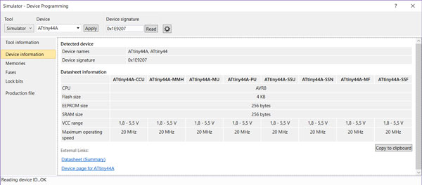
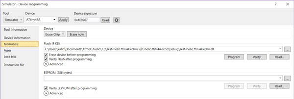
I found that fuses can be done also in Atmel Studio, by navigating in the top bar to Tools > Device Programming, and that I have to be careful when setting up them. When selecting the device, I can see also some datasheet information and what is loaded to the memory at the moment.
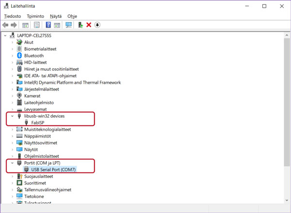
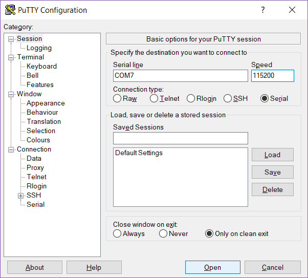
Then, I tried if the connection works using Putty installed in the Week 7. Preparing to set up Putty I checked:
- that the FABTinyISP programmer and my Heart board are visible in Device Manager and
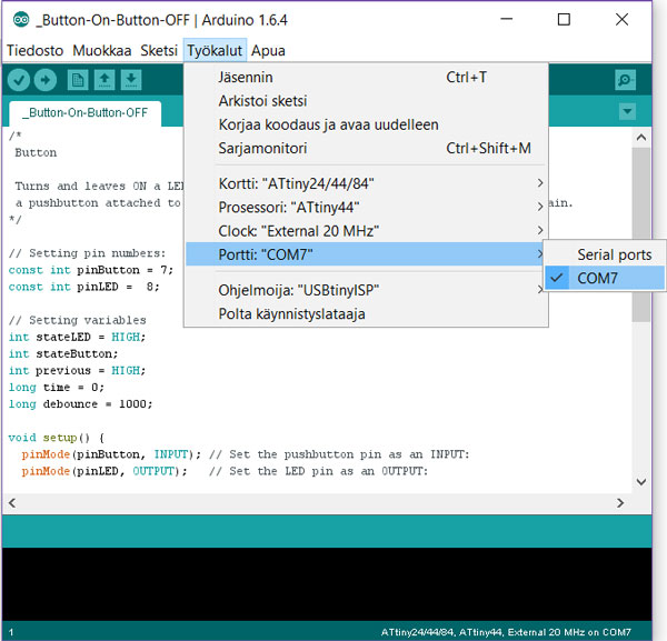
- on which port the programmer is connected [Serial Port (COM7)].
Select Serial > Serial line [COM7] > Speed [115200 baud rate] and press Open.
Programming Heart board using Arduino
Programming the Heart board to light up LED by pressing a push button in Arduino programing environment.
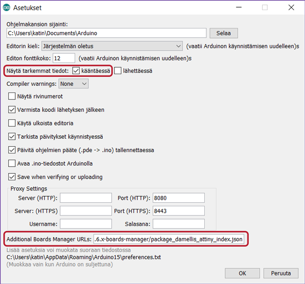
First of all, following the instructions of high-low tech, I installed the ATtiny support by navigating in the top bar File > Settings:
- Additional Boards Manager URLs // Add:
https://raw.githubusercontent.com/damellis/attiny/ide-1.6.x-boards-manager/package_damellis_attiny_index.json - Additionally, I selected Arduino to Show verbose output during: compilation.
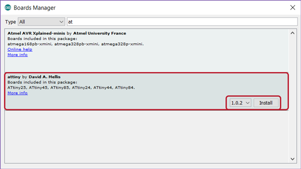
Next, I needed to install attiny library, which the Boards Manager found after installing the the ATtiny support, by navigating in the top bar Tools > Boards > Boards Manager.
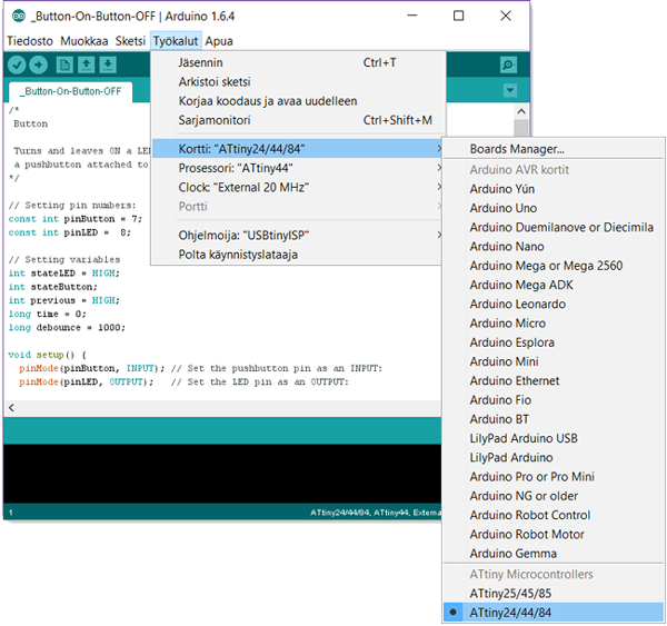
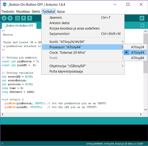
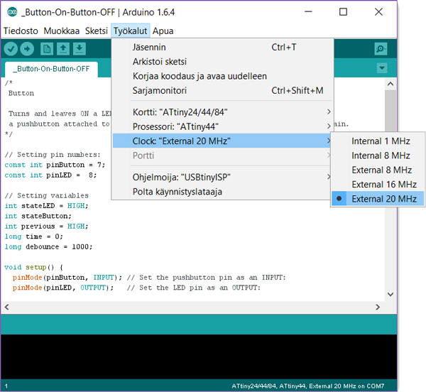
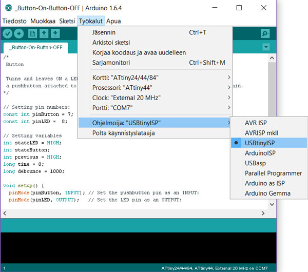
Then, by connecting my Heart board to USB and navigating in the top bar Tools, I selected correct:
- Board // ATtiny24/44/84
- Processor // ATtiny44
- Clock // External 20 MHz
- By default, the ATtiny was running at internal 1 MHz so, I configured it to run at external 20 MHz instead.
- Serial Port // [Check from Device Manager - in my case COM7]
- Programmer // USBtinyISP
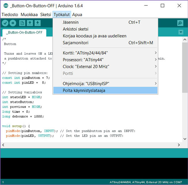
And finally, because I was going to program my Heart Board with Arduino IDE for the first time, I did Burn Bootloader for configuring the fuse bits of the microcontroller to make the board use the right clock source and speed. This phase I should do only once per board.
For burning the bootloader, USBtinyISP needs to be connected. Then, I hit 'Polta käynnistyslataaja'. (I noticed, that also the "Burn Bootloader" commands in the Arduino IDE environment are using AVRDdude.)
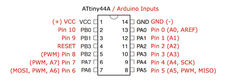
Arduino pins differ from the pin configuration model presented in the datasheet. Following pin confguration figure is edited to present the Arduino pins with a help of high-low tech site.
I started programming by using the Tutorials provided by Arduino.
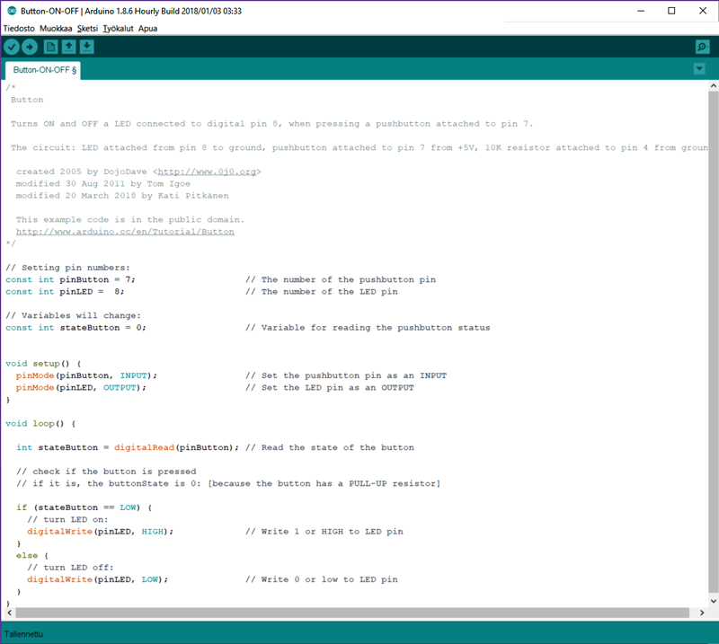
Modifying the Button example helped me to get started in experiencing to turn the LED ON when the button is pressed and turning the LED OFF when the button is released. Our local instructor Iván's documentation from the previous year helped me to understand how the pull-up resistor of the button affects to the code to make it work: contrary to convention, where the value is 1 or HIGH when a button is pressed, in case of pull-up resistor the value of the button is 0 or LOW when a button is pressed.
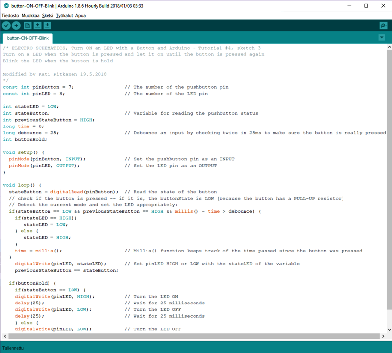
Second, I wanted to experience turning and leaving the LED ON when the button is pressed once and turning the LED OFF when the button is pressed again. For this, I utilized Electro Schematics Turn ON an LED with a Button and Arduino - Tutorial #4 and Arduino Debaunce -tutorial. By these examples, I got familiarized with debounce and millis() -functions. Debounce functions as an input, which means checking twice in a short period of time to make sure the pushbutton is definitely pressed. Millis() keeps track of the time passed since the button was pressed and returns the value of milliseconds as an unsigned long.
In addition, I wanted to have two different modes of using a pushbutton. For this, I added a second option, where the LED will start blinking when the button is pressed and hold. I utilized the Blink example to realize this option.
See the video on top of the page to see how the code works.
Here are the code -files of The Heart Shaped Echo Hello-World board I programmed this week.
- Atmel Studio code in c format // Turn a LED ON when pressed a button and OFF when released
- Arduino -code in ino format // Turn a LED ON when pressed a button and OFF when released
- Arduino -code in ino format // Turn and leave a LED ON when pressed a button, and OFF if pushed again, hold a button to blink a LED