
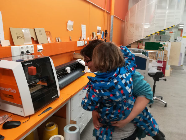
Our local instructor this week, Jari Pakarinen, guided us through the process of generating the necessary rml files, load them to the milling machine, prepare the machine and do the actual milling. We, after that, just needed to repeat the process with the board we chose. He later gave also some tips for soldering too. After Jari's instruction, some of us decided to stay to start also the group work, which is described in the group work page.
To Do
- PCB Fabrication.
- PCB Programming.
- Group work
The "Doing"
Create a PCB board
- Download design files (png)
- Generate the milling files (rml)
- Prepare the milling machine (Roland SRM-20)
- Mill the board
- Prepare for soldering
- Soldering
- Check everything is ok
Generate the milling files
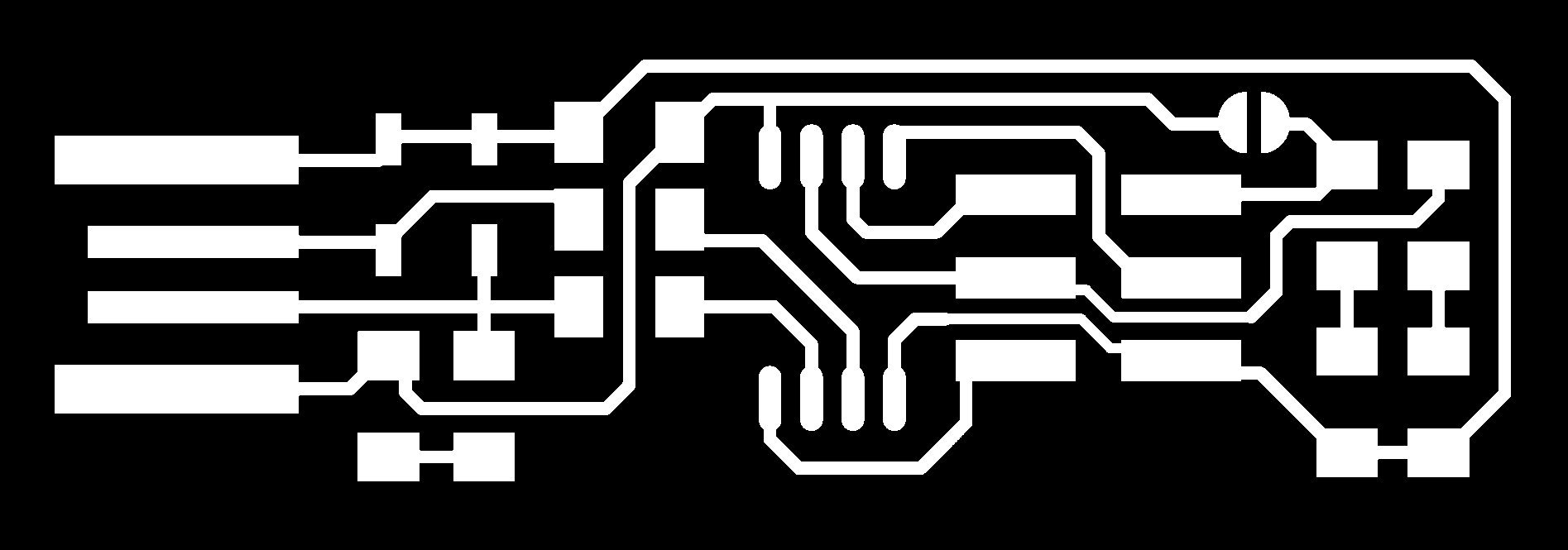
I downloaded the design files from Brian's page, the one containing the traces and the one containing the outline.
Then, using the fabmodules I generated the corresponding rml files.
Steps for the traces:
- In menu on top
- Input format: image (.png) ; and choose the png file for your traces
- Output format: Roland mill (.rml)
- Process: traces 1/64
- In menu on right
- machine: SRM-20
- offset (x0, y0, z0): 0
- cut depth (mm): 0.14
- Press
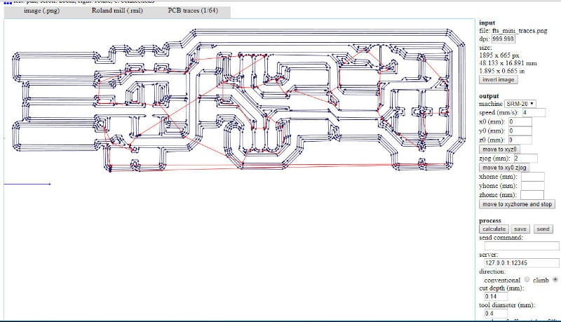
calculate - Once done, press
saveto download the file
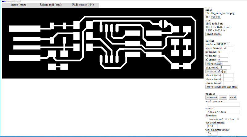
The rml file obtained:
- In menu on top
- Input format: image (.png) ; and choose the png file for your outline
- Output format: Roland mill (.rml)
- Process: outline 1/32
- In menu on right
- machine: SRM-20
- offset (x0, y0, z0): 0
- tool diameter (mm): 1
- Press
calculate - Once done, press
saveto download the file
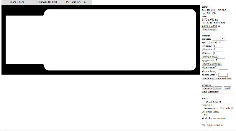
The rml file obtained:
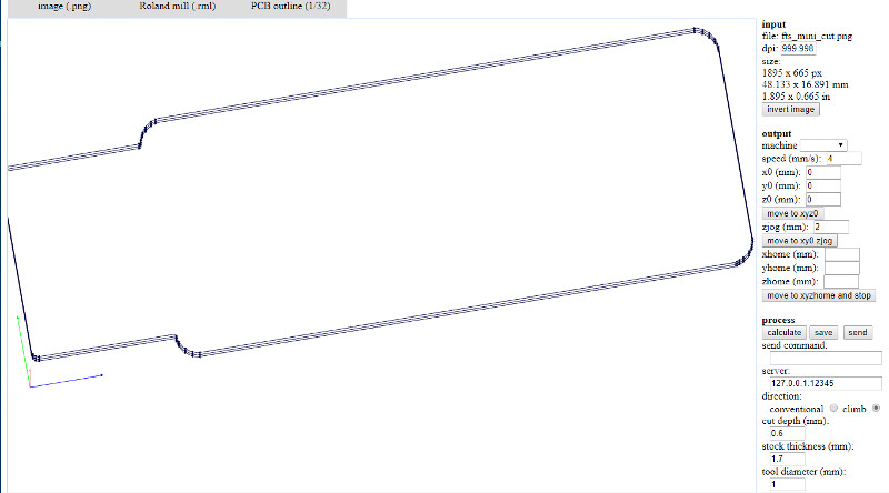
- The size from both files (top right corner) is equal
- The size is what is expected
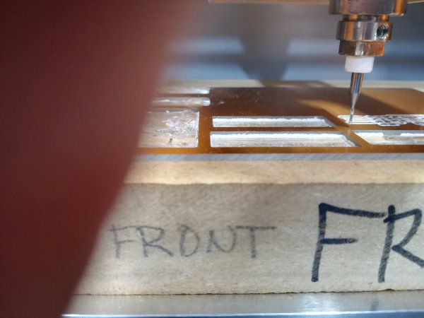
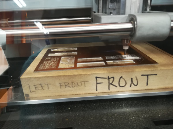
Mill the board
- The tasks to PREPARE THE MILLING MACHINE are:
- Open Vpanel application in the assignated computer
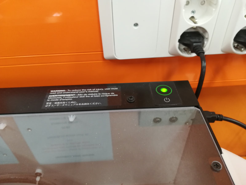
- Switch on machine
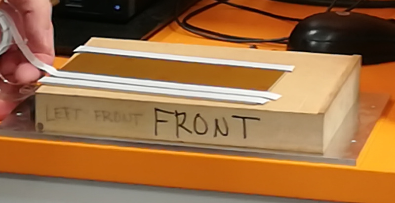
- Open machine and extract the bottom plate
- Check sacrifial board is leveled (not done by us)
- Stick the board to the sacrificial board with doubled sided tape
- Back in place and hold well
- Prepare the TOOLS
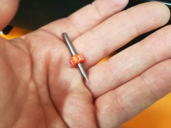
- V Shape bit.
- this is the bit we will use for milling the traces
- It's diameter goes from 0,2mm to 0,5mm, being the part we work with of around 0,4mm
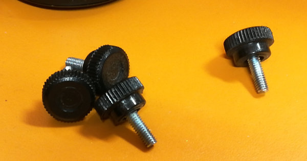
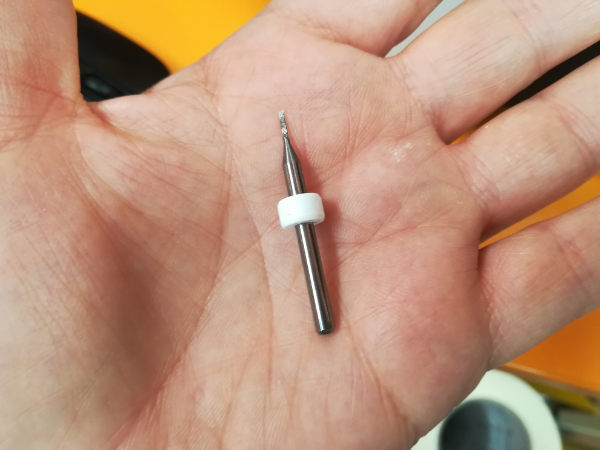
- Bit for cutting.
- this is the bit we will use for cutting the outline of the board
- it has a diameter of 1mm
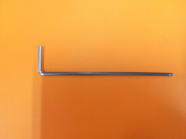
- Hexagonal allen
- We use this allen to screw / unscrew the bit from the head
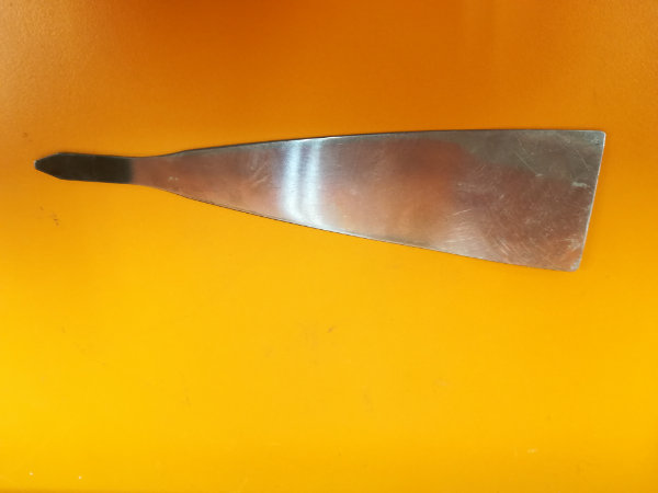
- Spatula
- We will use the spatula to extract the board, once finished, from the big piece of board
- SET THE ORIGO
- Put the bit for the traces
- Set the origo
- Trace, using the traces file
- Put the bit for the outline
- Set the origo
- Cut, using the outline file
- If you need to change the bit then:
- With the lid closed, press
Viewon the Vpanel to put the head close to the front part - Open the lid, and unscreew the bit enough you can remove it from the head. It is better to hold it with a couple of fingers.
- Put the new bit and screw it in
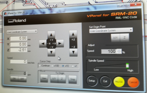
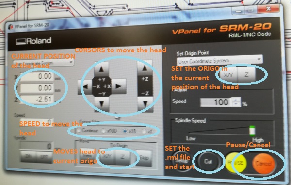
- Setting X, Y
- If you are changing from milling bit to cutting bit, you should not change the XY, or you would not cut on the expected place
- You can put it back to the XY origo if necessary by pressing the button indicated in the picture above
- If you need to set the X, Y
- Press the XY cursors to move the header to the desired X,Y position. This can be done with
speed > continuous - When the header is in the correct X,Y position, set the X,Y origo by pressing the corresponding button in the panel
- Press the XY cursors to move the header to the desired X,Y position. This can be done with
- If you are changing from milling bit to cutting bit, you should not change the XY, or you would not cut on the expected place
- Setting Z
- Press the Z cursor to lower it as much as possible without touching the surface. In this case use
speed > x100and reduce it tospeed > x10or evenspeed > x1if needed. It is important not to touch the surface, because the bit could break. - Open the lid, hold the bit with one hand while unscrewing the bit slightly. Help the bit to fell until it touches the surface.
- Holding it still, tighten again the bit to the head.
- Close the lid, and set the Z origo by pressing the corresponding button.
- Move the head up a bit with the Z cursor
- This is because Jari had once a bad experience with the head not doing that when preparing to cut
- Press the Z cursor to lower it as much as possible without touching the surface. In this case use
- Press
Delete Allto remove all files in the list - Choose the file (First, the traces; Secondly, the outline)
- Press
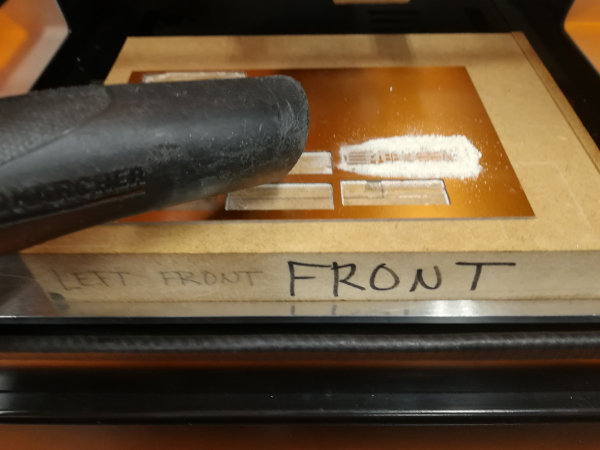
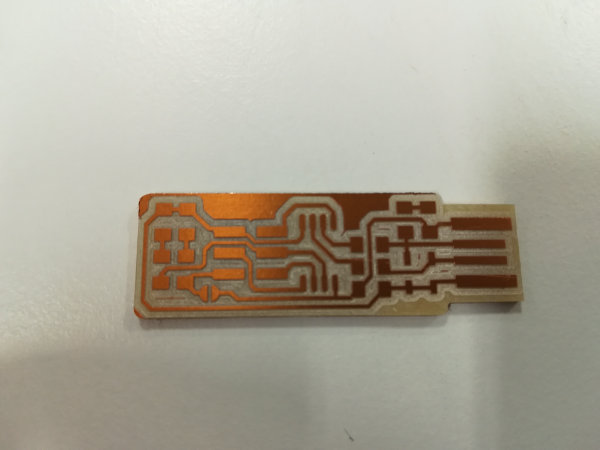
Output - Remove extra copper. As this is meant to connect to the computers' USB port, it is better to remove the extra copper from the tip
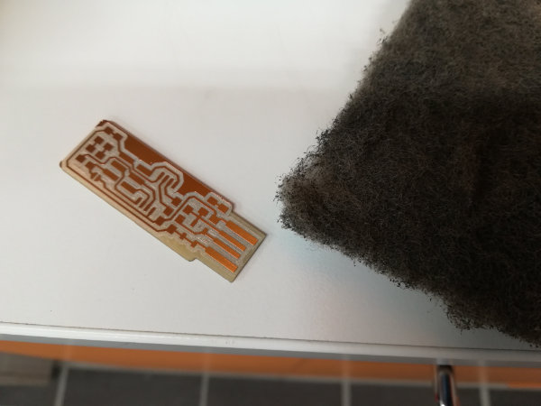
- Scrub upper coatingThe boards used are FR1. They have an extra coating that needs to be rubbed away because it makes soldering quite challenging
Cut in the vPanel,
and a new menu is prompted:
There are still a couple of things to do:
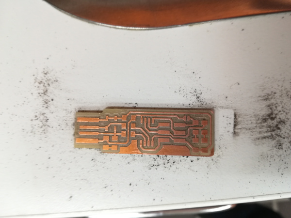
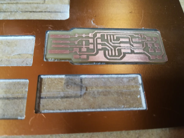
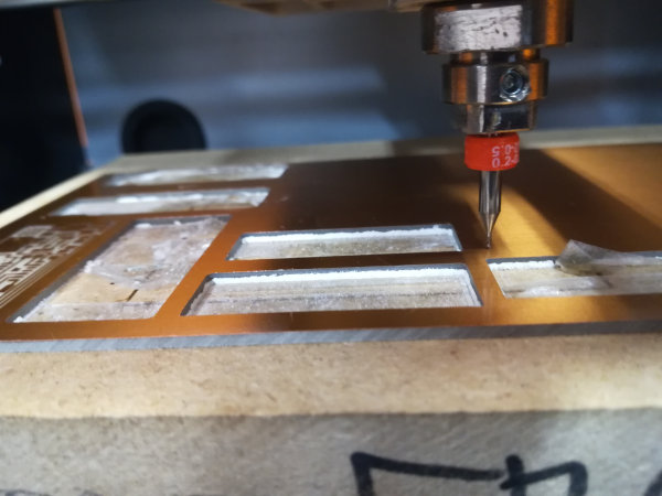
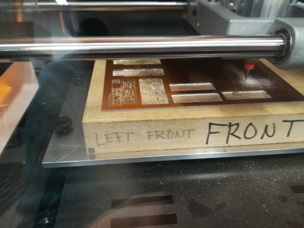
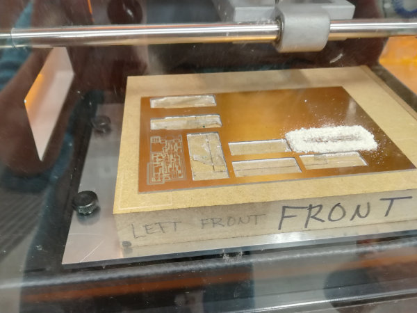
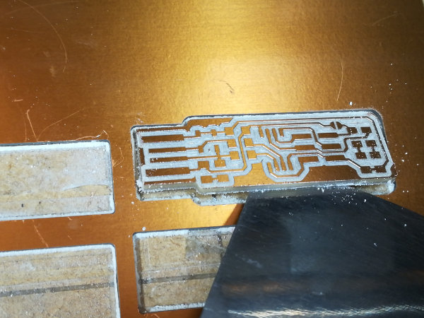
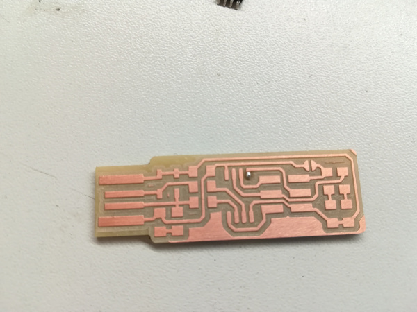
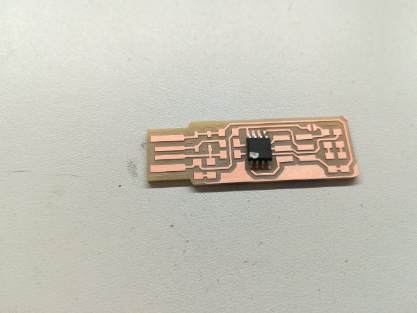
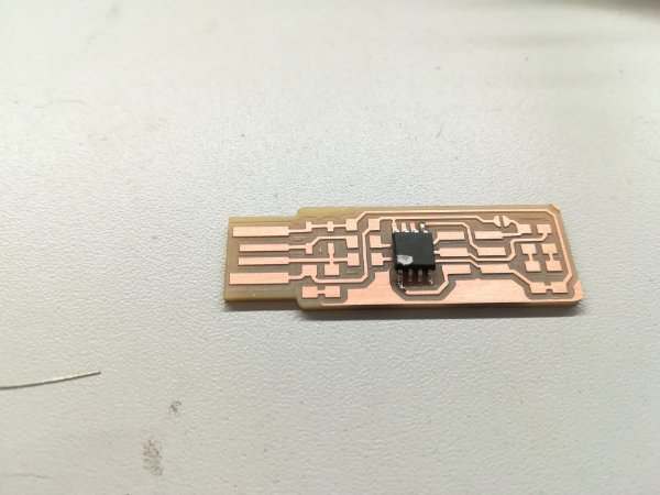
- The board is not traced correctly, with some parts traced or semitraced and others where the copper remains almost completely in the traces. This is most probably due to having the sacrificial board uneven, so the actual board does not have the same Z position in all its surface
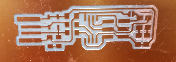 Example of not leveled sacrificial board
 - If you do not see enough "dust" coming from the bit, then most probably it is not milling. Or something is wrong (for example, the bit is not screwed tight enough), or the cut depth is not enough.
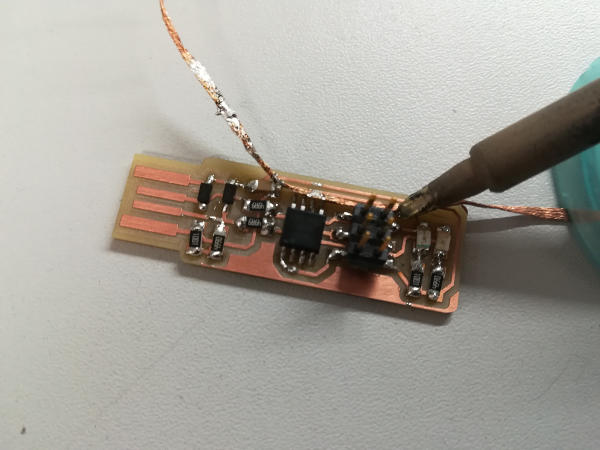
Soldering
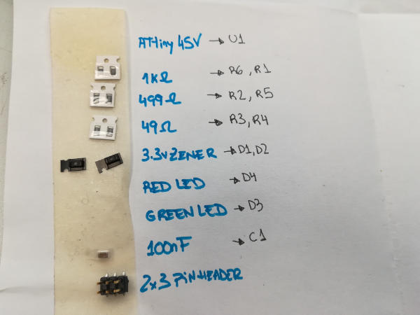
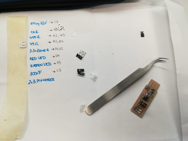
- 1x ATtiny45 or ATtiny85
- 2x 1kΩ resistors
- 2x 499Ω resistors
- 2x 49Ω resistors
- 2x 3.3v zener diodes
- 1x red LED
- 1x green LED
- 1x 100nF capacitor
- 1x 2x3 pin header
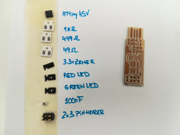
Taking into account the information in the last images, I completed the list with the components' names given in those images:
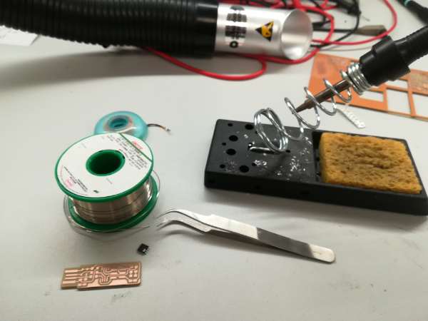
Then, I prepared the soldering place:
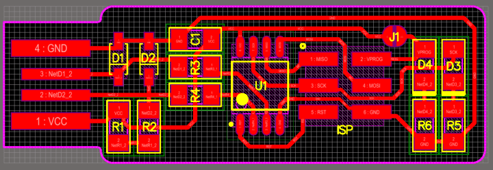
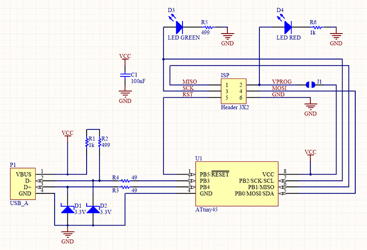
The plan for the board was:
- start with the chip (just because I thought it was harder)
- then, go from right to left soldering
Switch on the soldering station, and wet a bit the sponge on the base.
Then, I followed these steps to solder one component are:
- put a bit of solder in the pad of one of the sides/legs to hold the component
- position the component over it and heat the solder with the iron tip so it melts enough to hold the component
- proceed to solder the other side/legs of the component
- if the component has several legs, you may start from one corner, and then continue with the opposite corner; and then with a leg on the other side. This way, the heat is better dissipated.
- Soldering properly the first side/leg, that is, resolder the first pad that was holding the component
Things that can go wrong
- There are some components that require certain orientation in the circuit. That is the case of the LEDs and the Zener. Check the marks!!
- shortcircuits, that is, solder that joins two different paths: use the desoldering braid to remove the solder
- components bad positioned: use the desoldering braid to remove the solder
- Put the thread over the solder to remove
- Press with the soldering tip until the heat melts the solder
- Pull the tape fast, and the solder gets stuck to it
Optional: Programming the board
- Followed again Brian's page
- Checked Jari's page
- Used Iván's programmer
I first tried to do this in Linux (Brian's and Iván's recommendation). I have a windows 10, and I was not willing (yet) to make a new partition or going for a VM, so when Neil show the Windows Subsystem for Linux I was quite happy. I installed an Ubuntu in my laptop and started to follow Brian's instructions. Everything was going quite smoothly... But! It turns out my recently installed WSL does not recognize the USB. So back to the starting point.
I then followed Brian's instructions for Windows. Summarizing:
- Install all the needed software (with screen shots at Brian's instructions)
- Install Atmel AVR Toolchain for Windows
- Install GNU Make
- Download avrdude and unzip it to
c:/Program Files - Add to Path (
Advanced System Settings > Environment Variables > User varianles> Path > Edit) the values:C:\Program Files\avr8-gnu-toolchain\binC:\Program Files (x86)\GnuWin32\binC:\Program Files\avrdude
- Install drivers for the programmer:
- Download Zadig and launch it
- Plug in your programmer, and select the "USBtinySPI" device in the list
- Select the driver: either libusb-win32 or libusb0
- Get and Build the Firmware
- Got fts_firmware_bdm_v1.zip from Brian's and unzipped it
- Run
make
- Program the ATtiny45
- plug my board into a USB and Connect the programmer to the ISP header on my board
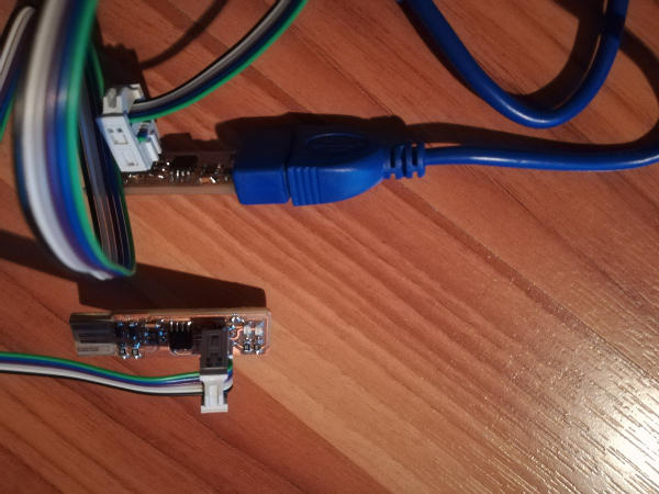 My board connected to programming board
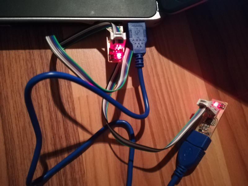 My board connected to programming board and computer
 - Run
make flash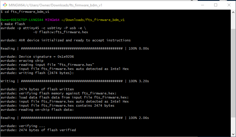 Result when
make flash - Run
make fuses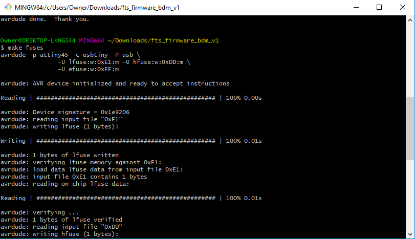 Result when
make fuses
- plug my board into a USB and Connect the programmer to the ISP header on my board
- Test the USB Functionality
- In Windows, check if you can see it with the
device manager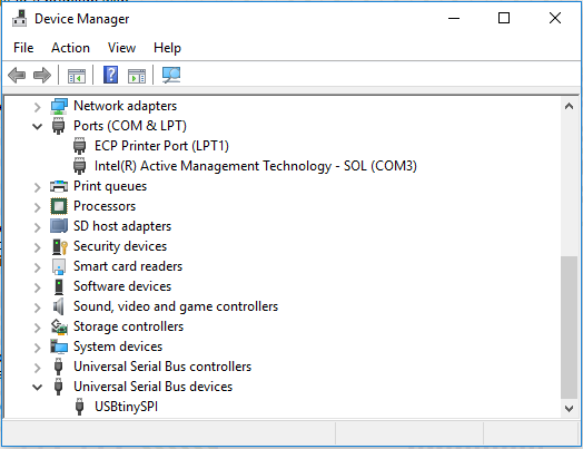 Look for your programmer in the device manager
- In Windows, check if you can see it with the
- Blow the Reset Fuse
- Run
make rstdisbl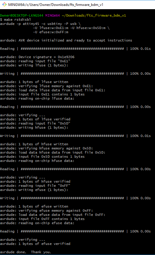 Result when
make rstdisbl - Remove the bridge on the solder jumper
 Removing the bridge of the solder jumper
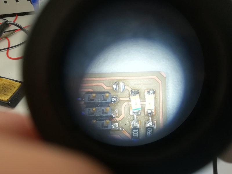 Bridge removed
- Run
- First, the download link for the AVR toolchain has changed to here
- Second, I had (of course) some issues when installing, being necessary to install everything as administrator (my fault, did not even think about that). I had all the time problems with the driver for the programmer (I had to replace the driver all the time with Zadig) and I guess it is also because I did not install Zadig as administrator.
- In the last two steps, that is, Blow the Reset Fuse, I got all the time an error. When I tried
I got the followingmake rstdisbl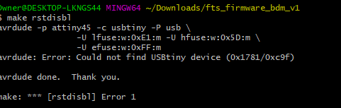 Error whenAnd this time reasigning the correct driver through Zadig did not work. Iván then had the idea of pluggin his programmer to my laptop and mine to his. And this way, it worked
make rstdisbl
Resources
- Fabmodules
- Brian's page
- Roland MonoFab SRM-20 Compact Milling Machine
- FR-1 circuit board
- Soldering station
- Electronics components
- Software installation needed for Windows 10 from Brian also
- Iván's page
- Jari's page
- Outline of the board
- Traces of the board
Once done
Summary
- I have learnt to use fabmodules to get the paths for the traces and the outline of a board design
- I have learnt to prepare the milling machine and fabricate the board
- I have soldered all the different components to the PCB I have fabricated
- I have programmed my programmer
- We had some team work to characterize the Milling Machine in FabLab Oulu. The results are summarized here
Difficulties
- Can you see the line on this component? Me neither! Positioning the zener in the correct alignment is quite a task. It is difficult to guess which part is the catode
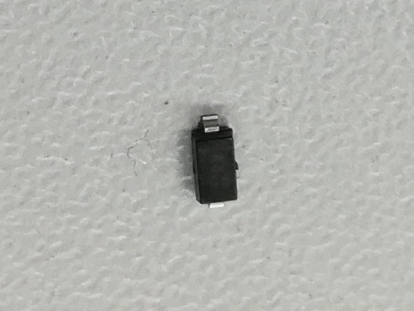 Can you see the line?
 - Although Brian instructions for programming are very clear, I had some issues with my laptop recognizing there was something in the USB port.
Learnings
- When it is said "slightly tight the bit to the header", it means tight it well.