
Our local instructor this week was Juha-Pekka Mäkelä. He did an overview of our possibilities for the network and communication. Then, he said something like: as we are in Oulu (you know, 5G, 6G...) it would make sense to go wireless. And I thought he was right. I borrowed from him some XBee modules. XBee is a radio communication module from Digi. If I have the time, I also want to test one of the serial bus communications
To Do
What would it do? I want to switch on/off the LED at board from week 7, Electronics design when one of the hall effect sensor at board from week 11, Input devices detect the magnet is very close to it. This will allow to switch off the LEDs of the thermometer when the wardrobe doors are closed, for the final project- Understanding XBee modules
- Wireless communication between boards
- Try one serial bus
The "Doing"
Understanding XBee modules
- PAN Id: identification of the network. Every component of a networks shares this
- My address: own address of 16 bit, assigned by coordinator. The value for the coordinator is 0
- Destination address: determines which node(s) in the network will receive the data you send (it is in DL (low) and DH (high)).
- each node's address can be found in the reverse of the board
- If you want to broadcast, use DL =FFFF
- Operation channel
Wireless communication between boards
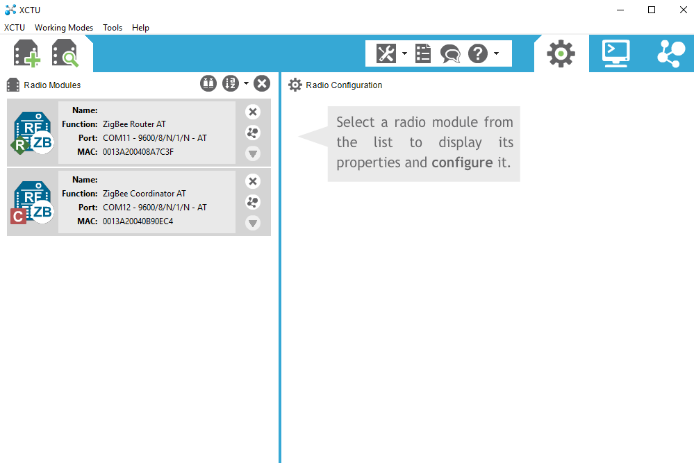
To configure the network, you need to download XCTU. First time you open the application, you get the following:
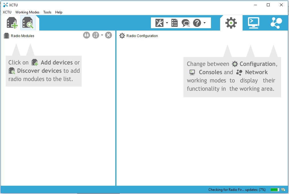 You need to have all the modules connected to the computer. Then, as it says, you need to click on
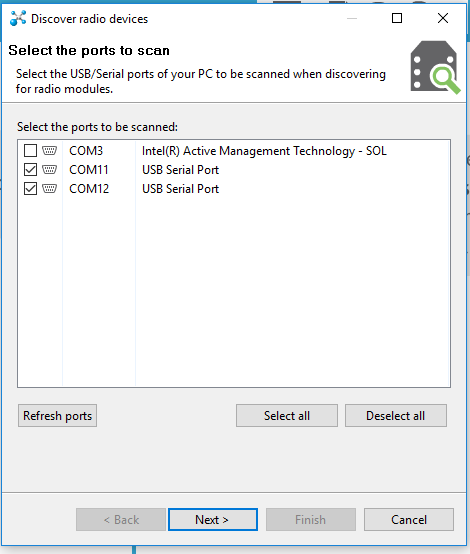
 Add devices or Discover radio modules connected to your PC. When pressing discovering, you will need to select the COM ports where your XBees are plugged.
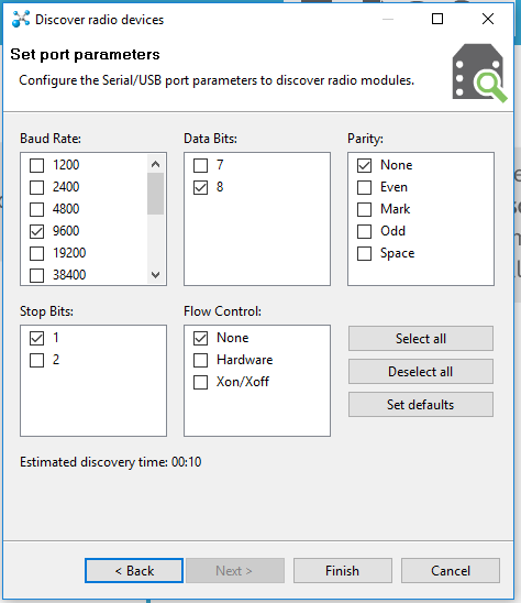
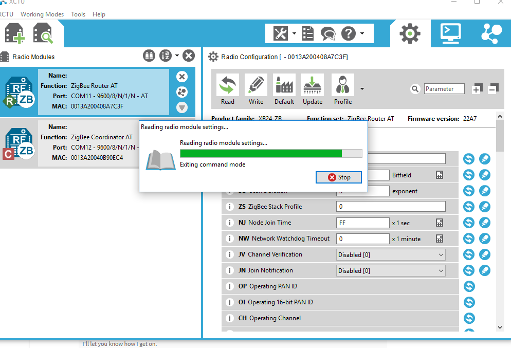
 It will also allow you to change some settings. I just leave them as they are:
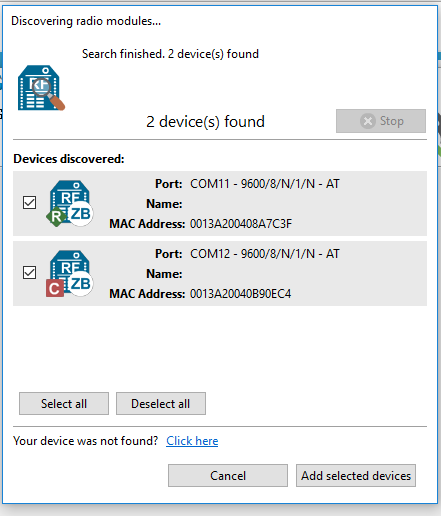
 When ready, it will then show the results. Choose the boards to add them to the network you want to form
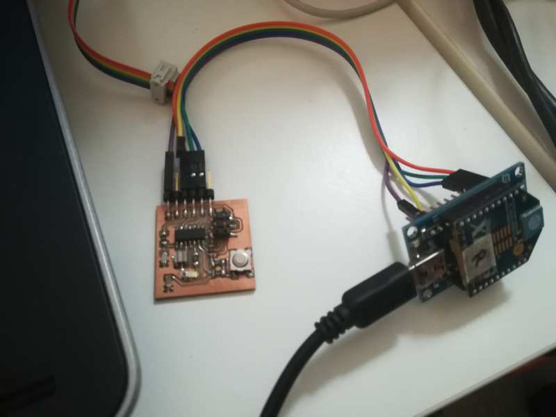
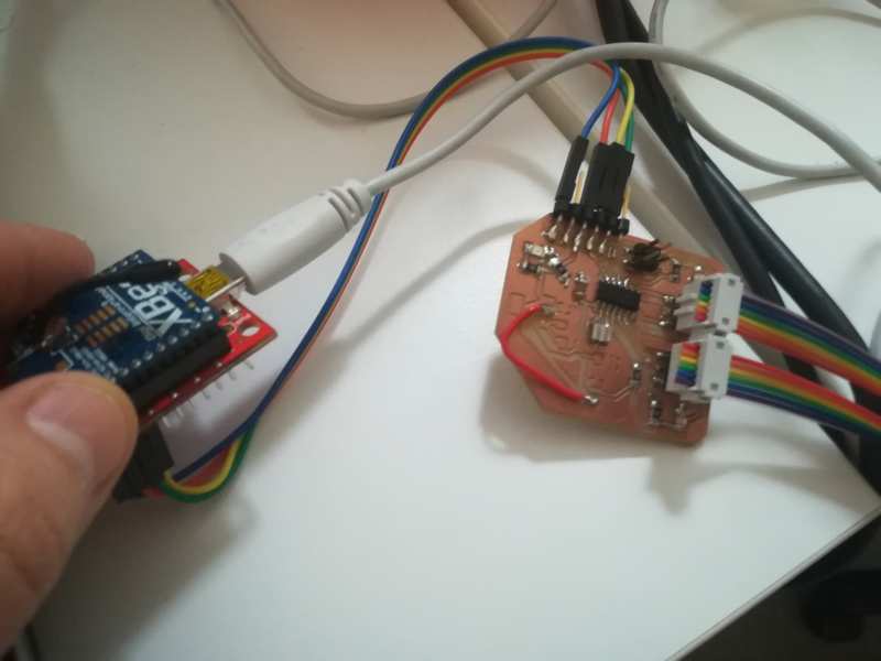
 Then, I connect each of my boards to each of the Xbee modules. Xbee module is connected to computer through its usb adapter board. Then, I connect the Xbee usb adapter board to my own board FTDI pins. The pins are labeled in the Xbee board: I get Vcc and ground to my Vcc and ground, and then the out and in pins (labeled DIN DOUT) to my board in (receiving, labeled TX by Neil) and out (transmitting, labeled RX by Neil) pins.
Serial bus
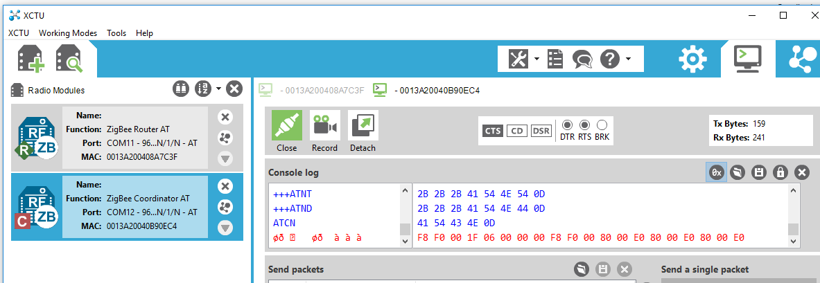
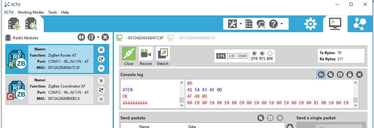
The parts of the code for the actual sending/reading are shown bellow.
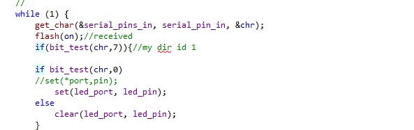
Getting information in LED board. Direction set at the bit 7 received: if 1, then read instruction (at bit 0 received)
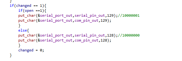
Sending information from Hall Effect board
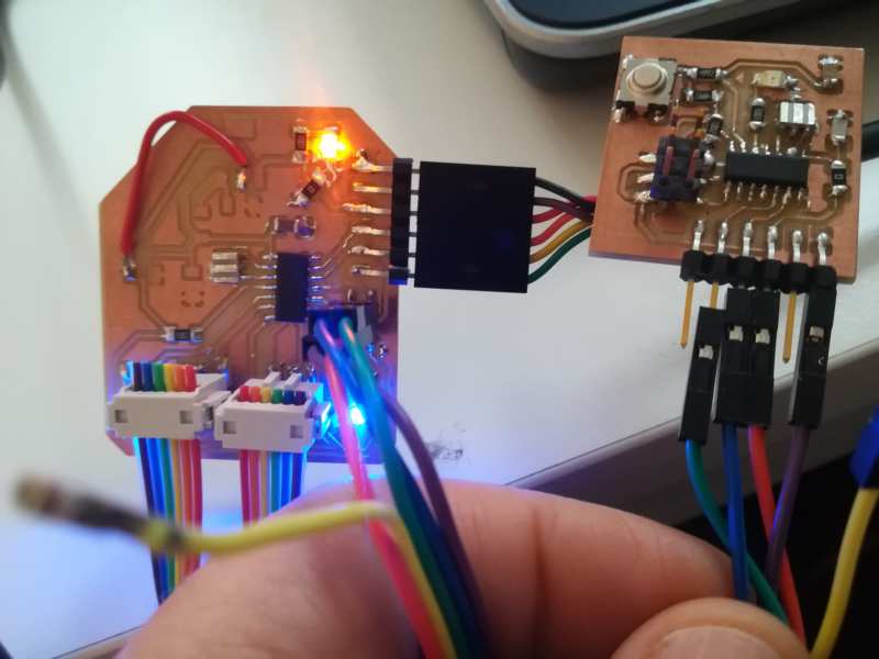
The 2 boards connected with a bus
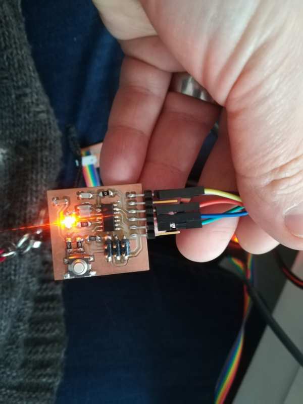
The Led from the receiver is on
Resources
- XBee datasheet
- Pages from Juha-Pekka Mäkelä and Antti Mäntyniemi
- Neil´s code from here and there
Once done
Summary
- I have managed to build a wireless communication network with 2 Xbee modules with addressing
- I have managed to build a serial communication network with 2 modules with addressing
Difficulties
- Main issues came from me: At some point I commented the code t needed for the initialization of the registers, so the code was not working; and it took a while to notice that code was commented. Once I put it back, everything went smoothly
Learnings
- Double check all the code, even those parts you think were working properly previously
Files
- main.c file for sender ( hall effect board)
- main.c file for receiver ( led board)