Assignment 11
4.4.2018
Topic: Input devices
Goals of this week:
- Describe your design and fabrication process using words/images/screenshots (Individual)
Describe your design and fabrication process using words/images/screenshots (Individual)
Explain the programming process/es you used and how the microcontroller datasheet helped you (Individual)
Explain problems and how you fixed them (Individual)
Include original design files and code (Individual)
- Measure the analog levels and digital signals in an input device (Group) (LINK)
Learning more about this week´s assigment
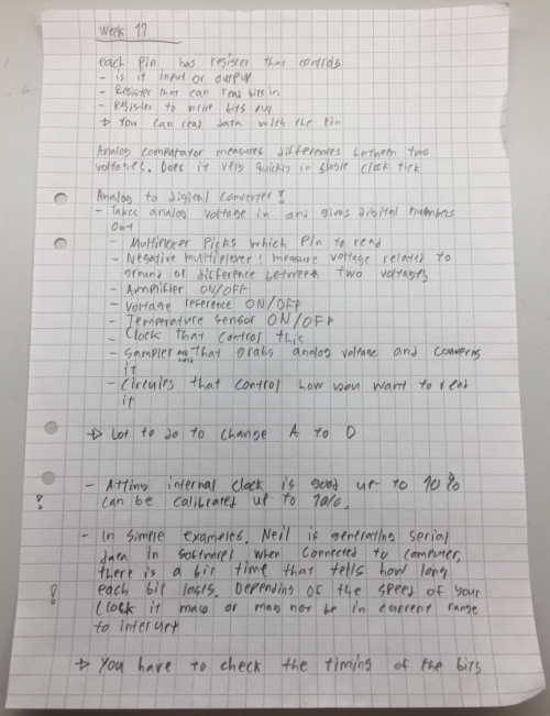
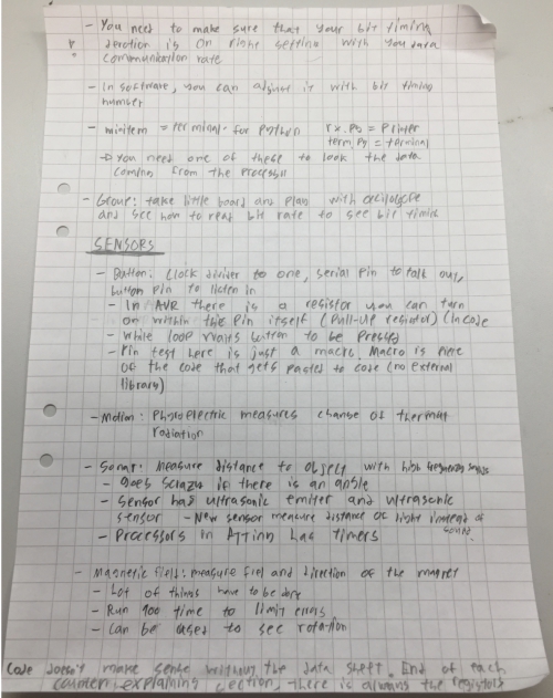
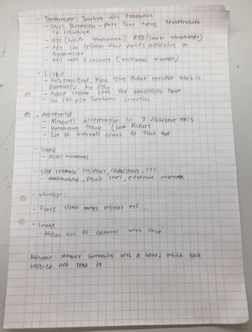
Before brainstorming anything, I looked through Neil´s lecture once more and made the following memos:
I wanted to make something that I could use in my final project so I decided to use one of the following sensors:
- Step sensor to create touch surface
- Sound sensor to give voice commands
- Light sensor to change the brightness of the light according to light
From these, I decided to create light sensor because it is something that I will definetly have in my board. Light sensor
can be made just by sensing overall light or through synchronic detection. However, I don´t have any need for the synchronic
sensing so I will just create simple light sensor board which is able to identify when the room gets dark.
Next it was time to learn more about how to create the light sensing board.
Creating light sensing board
I decided to follow Neil´s schematic but change my design as follows:
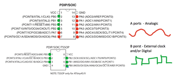
1: Use ATTiny44 insted of ATTiny45
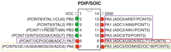
When I was comparing ATTiny44 and ATTiny45, I saw a big differenece in available ports:
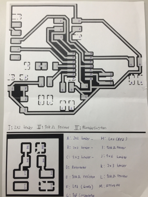
At first, I had problems to understand how the components use ATTiny ports, but after a while I got to know the basics. Bellow,
is Neil´s board, corresponding pins in ATTiny44 and decription why those ports are used:
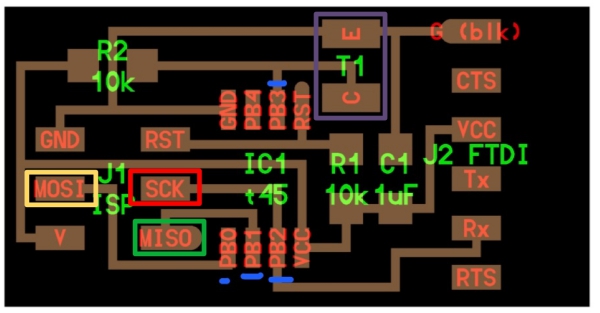
- MOSI (Yellow box): For programming ----
- SCK (Red box): For programming -----
- MISO (Green box): For programming ----
- C-E (Purle box): One pin for the sensor, it can be any of the boxed ones as long as it is analogic
Therefore, there are at least 4 pins to be used for other sensors and components so this board should work fine in my final project.
If I then need a board with more ports, I will just change my schematic and assemble a new board, it shouldn´t be too time consuming.
2:Put sensor to another board
I want to be able to place the sensor of my final project to place where it can be hiden from the views. I also want to put multiple leds
to different places so I decided to use small extra boards connected to my main board. This can be done simply by adding 2x2 headers to my
main board for the small board which then include my sensor and or led´s. The latency and resistance shouldn´t be problem as long as the
connection cords aren´t too long.
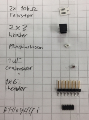
Next, I picked all the parts shown in Neil´s design to help me to visualize the board. However, our lab had different light-sensor´s so I ended
up choosing Photodarlington.
Then I created "To Do" list to schedule my time for Mon-Wed efficiently:
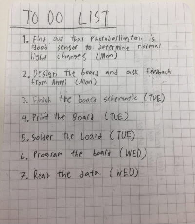
So, before going any further, I decided to learn more about Photodarlington sensor to understand if it can be used in my project.
Photodarlington
To learn more about the component, I had to located its datasheet. to do this, I went to Digikey website and used item
code found from the component storage shelf (Red box)
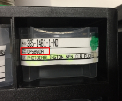
I found the component and got access to its datasheet from the Digikey
product page. From the datasheet I found out the wavelenght graphs about the area of wavelenghts that photodarlington identifies:
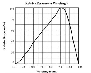
This revealed that -----
Designing the board
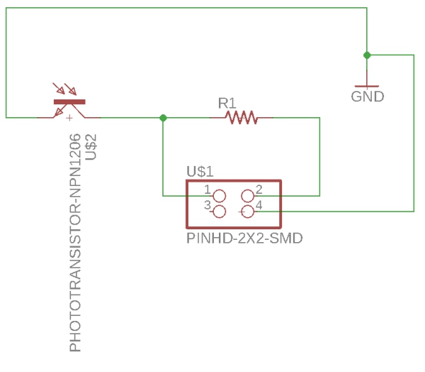
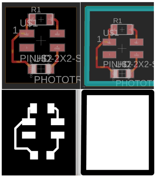
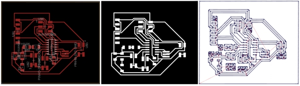
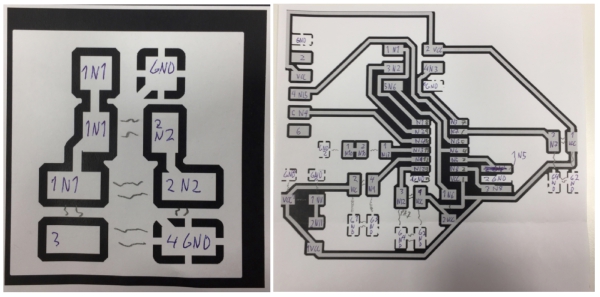
Deciding the board went forward as during the week 7. I began by designing small board for the sensor by following Juha-Pekka´s example from his input week.
(Upper left: BRP 1/2, Upper right: BRP 2/2, Bottom left: Traces.png, Bottom right: Interior.png)
I had some probelms with the milling. First, I milled the board wrong way (Left) and second time I cut it wrong way (Middle).
However, second time board wasn´t broken so I used it. Soldering was pretty easy (Right).
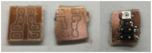
Sensor board includes following parts:
- 10k ohm resistor
- Photodarlington
- 2x2 header
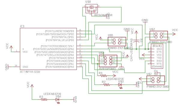
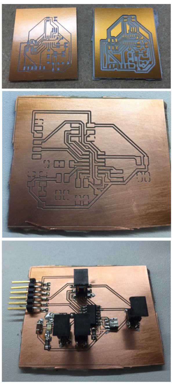
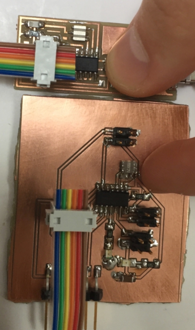
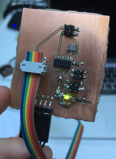
Then I created the main board:
Again, I had problems with the milling. First I milled the board wrong way (Up left) and then I milled the board so that some of
the connectors were too thin (Up right). Finally, I managed to print the board correctly (Middle). Soldering was harder, but I managed
to assemble the board (Down).
Mainboard includes following parts:
- 3x 10k ohm resistor
- 3x 2x2 header
- Resonator 20mghz
- Led (Green)
- 1uF condensator
- Led (Red)
- 1x6 header
- 2x3 header
- ATTiny44
Programming the boards to measure light changes
I began the programming by fiquring out how to connect the jump cord. To help me on deciding
this, I made the following sketch of my pins on the
programmer and on the mainboard:
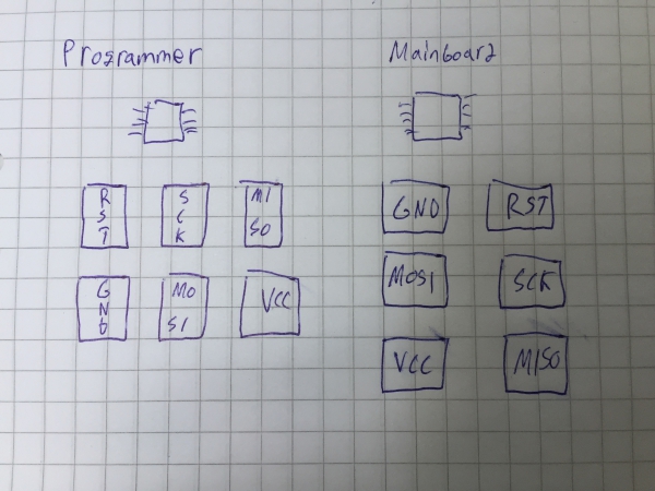
According to this sketch, I then connected my cords as follows:
Then I tested the programmer with Neil´s example board to see if the VCC-Ground led (Green) would
work. After uploading the code, the led was
working, but it was shining on very low light level.
Therefore, I checked the threshold voltage of the led.
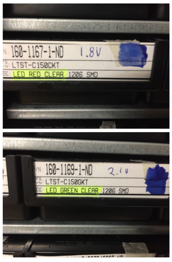
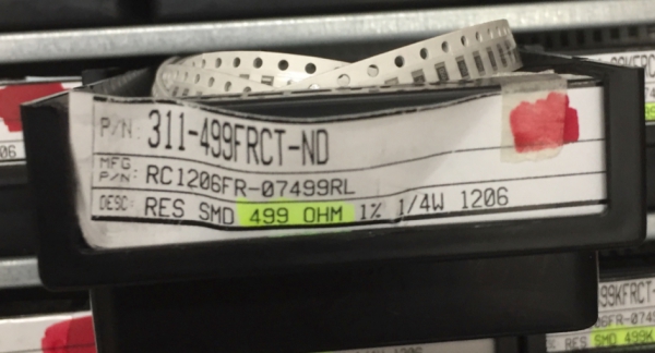
It was 2.1v so I calculated that I would need a 145 ohm or bigger resistor so my 10k ohm resistor before the green led was
way too big. Therefore,
I changed the resistor to 499 ohm resistor.
Then, the led was shining much brighter:
Problems with C-code
I began creating my own code by taking Neil´s example file for the light sensor.
then I began to modify it according to my own needs.
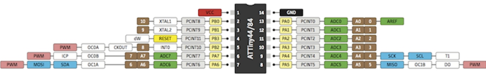
Neil was using Attiny45 and I was using Attiny44 so I made following sketches to help me on the problem solving. First: Second: Components and their placements,
Third: Pin names and Fourth: Neil´s ATTiny45 pin use and my ATTiny44 pin use:
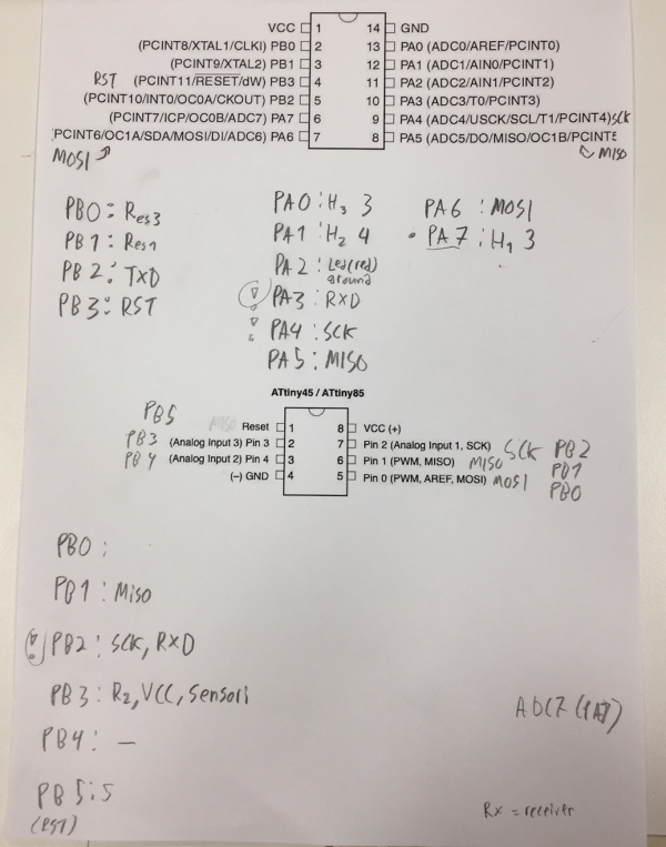
I made two changes for the code according to third picture:
1.Changed PB2 in code to PA7
Neil uses PB2 as a pin for sensor on ATTiny 45. I decided to put my sensor to PA7 port in ATTiny 44 so I changed the port to PA7.
1.Changed Mux code to respond to ADC7(PA7) pin needs
In Neil´s code, there are following lines refering to input channel selection:
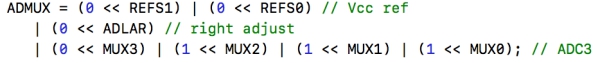
This piece of code references to ADC Multiplexer Selection Registe. I had to change the MUX code according to following table found
from the Atmel datasheet (Copyrighted by ATMEL)
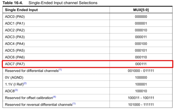
For ADC7 (PA7) MUX code is 000111 instead of ATTiny45´s 000011 so I changed this part of code as seen up in the code.
When I tried to upload code now to the board, I got error that refered to REFS2 selection problem. From ADMUX register list, I found out
that ATTiny44 doesn´t have this register (Copyrighted by ATMEL):
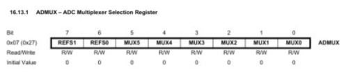
Therefore, I deleted this register from the code and tried again. Everything went forward normally until program-usbtiny-fuses-part, however,
terminal wasn´t able to find avr. To solve this problem, I reinstalled Crospack AVR and after that, I managed to send the code.
However, my sensor wasn´t doing anything.
Solving the programming problem
It took me 5 hours, but finally, I managed to solve the problem in 3 steps.
Fixing Shock problem
When I powered the mainboard, I noticed that ATTiny44 was getting warm. This indicated that I had shock in my board. I located the shock
to one of my 2x3 pin header pins which was soldered wrongly. I fixed this problem and ATTiny44 was working fine.
Fixing Sensor problem
With help of my fablab student fellow Ari
, I found out that my sensor board was not working properlly. I found out that the photodarlington sensor
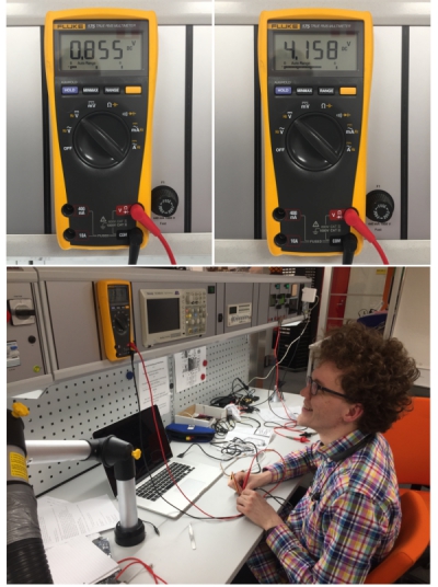
was soldered partly to the ground, which meant that my sensor board had shock. Therefore, I resoldered and tested it with a multimeter and
a powersupply. According to this test, sensor board was now working properlly.
Connect mainboard and sensorchip correct way
Due to my schematic choses for the use of pin headers pins, I had problems to connect mainboard´s header´s pins correctly with sensor boards´s
header´s pins. Again, I solved this by using a multimeter and a powersupply. With this, I was able to connect the boards correctly as follows:
(Board [function of port] (port number))
Mainboard [Microcontroller port] (3) [VCC] (3) [GND] (4) [GND] (2)
Sensor board [Microcontroller port] (1) [VCC] (2) [GND] (4) [Empty] (3)
Fixing 2x2 pinheader problem
When I connected the sensor board correctly to my mainboard, the current was not going correctly to the sensor board. I located this problem to
the 2x2 pin header: one of the pins was not soldered properlly so I soldered it again.
After this, I tested the board and it was working correctly. By using multimeter and manipulating the photodarlington sensor with my finger, I
managed to change voltage!
Getting the serial output out from the sensor
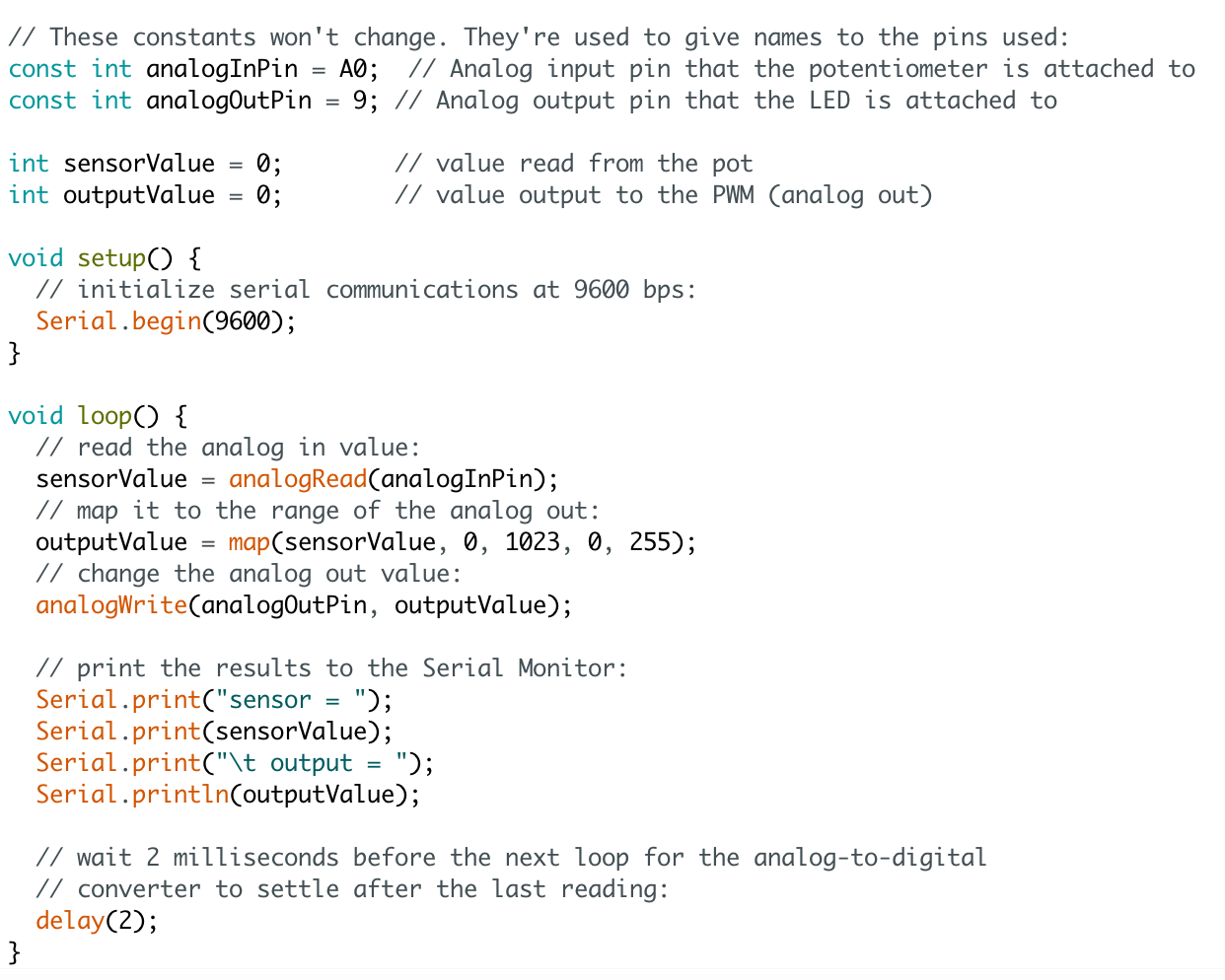
I had problems to get Neil´s C-code to work, so in the end, I decided to reprogram my board with arduino, because it´s simpler. I opened arduino
and clicked File > Examples > 03.Analog > AnalogInOutSerial to open example that could be used as a base for my code. The code can be seen bellow:
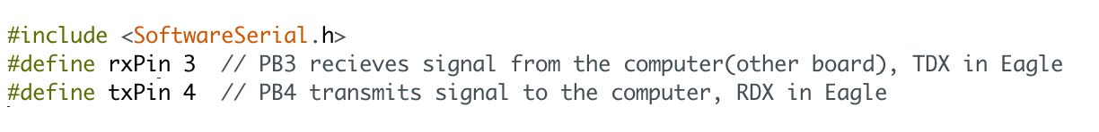
I began to edit the code by including SoftwareSerial.h to be able to use serial commands and rxPIN and txPIN my mainboard uses to enable serial
communication. Pin numbers were identified by using Arduino-Attiny44 pin converter table:
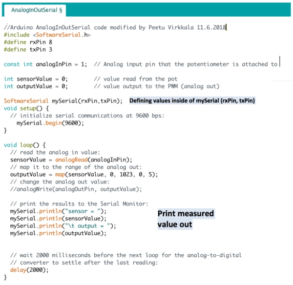
Then I made few other changes into the code that can be seen below with comments:
When this was done, I clicked Tools > Burn Bootloader to burn bootloader. I also defined board, prosessor, clock and port from Tools option as seen bellow:
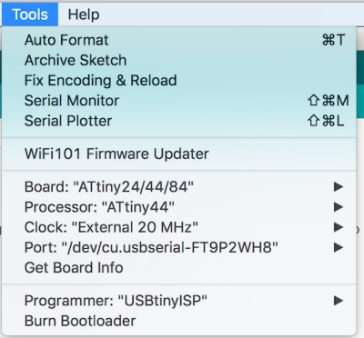
Next, I clicked "verify" and "upload" to upload the code to my board. Then I opened serial monitor by clicking "serial monitor" icon. Serial communication was
working: I got values between 0-5 according to brightness that the light sensor sensed (5 = Minimum brightness, 0 = Maximum brightness).
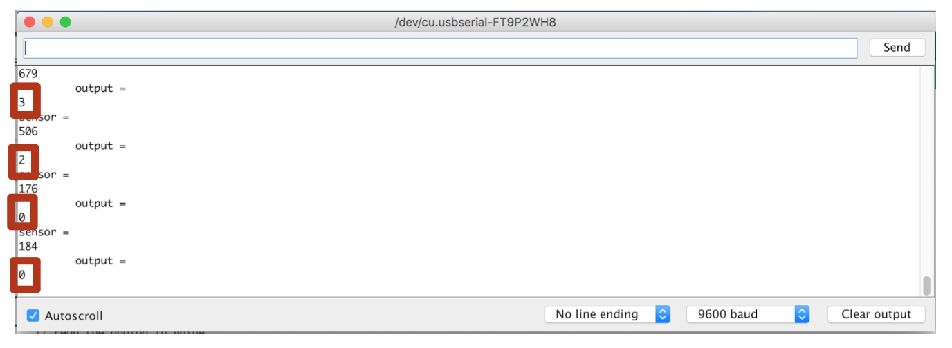
Here is the VIDEO about the serial communication in action.
FILES made THIS WEEK
Mainboard brb. file
Mainboard sch. file
Sensor board brb. file
Sensor board sch. file
C-code (first code)
Make-file (first code)
Final code as .ino file

This work is licensed under a Creative Commons Attribution 4.0 International License.