- Add an output device to a microcontroller board you've designed, and program it to do something (Individual)
- Measure the power consumption of an output device (Group) (LINK)
Deciding what to do
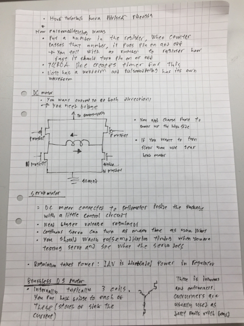
I began this week by rewatching the global lecture to understand the topic better. I made following memos according to this lecture: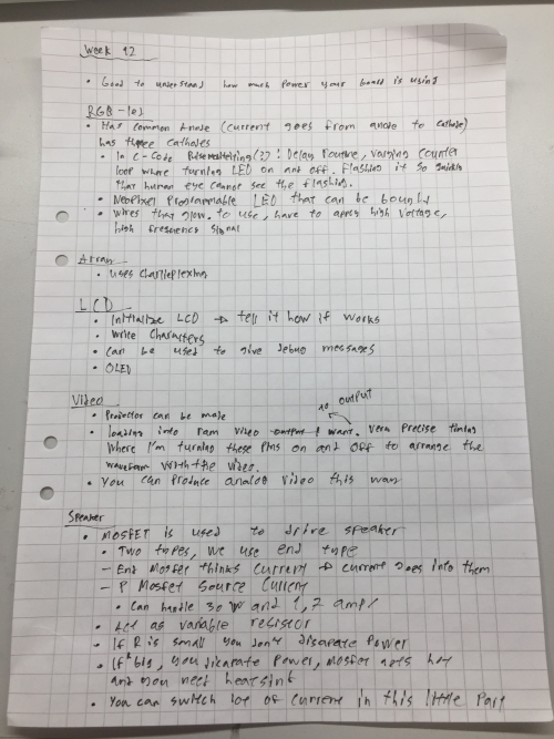

I want my sensor to be either an RGB-led or a speaker. RGB led I would use to light my final project in dark whereas the speaker would be used to give voice notifications for me when I´m wearing the helmet, for example when I press the buttons in somekind of controller, I would get voice notification from the press.
I decided to use RGB-led for this week instead of the speaker. In my final project, I´m planning to use multiple RGB-LED´s to light my final project. I will prototype this by using the Attiny44 microcontroller of the mainboard which I made during the WEEK 11 connected to RGB-LED board which I will make during this week. When this basic prototype is made, I´m aiming to change the color of the RGB-LED according to voltage value got from my light sensor board made during the WEEK 11 which can be connected to mainboard as a input device.
To achieve my goal, I have to create RGB board to be connected to my mainboard from the WEEK 11. I began by creating a board layout in Eagle for the RGB-LED board. I used Neil´s RGB-LED board layout as a reference as seen bellow:
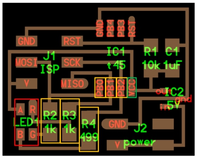
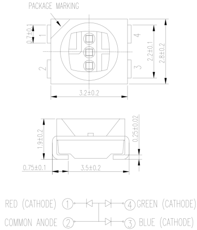
The layout reveals that:
- I have use different kind of resistor for different LEDs - different color LEDs have different threshold voltages
- I have to use three microcontroller ports to be able to change the color of the RGB LED (yellow boxes) - Change ports values between 0-1.
- I have to use one VCC port of my Mainboard (green box)
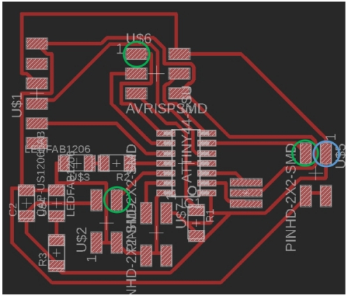
After this analyze, I designed my RGB-LED board in EAGLE. Corresponding pins are circled as above:
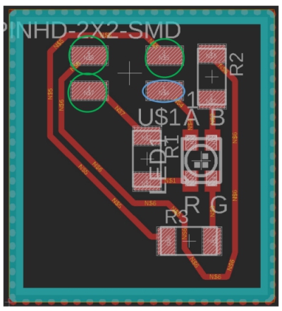
The Schematic can be seen bellow:
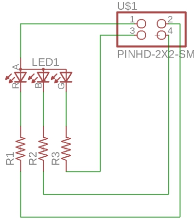
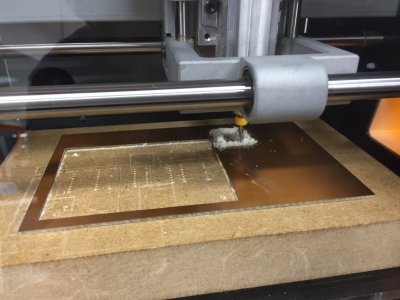
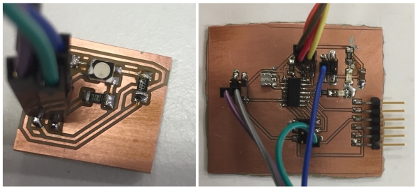
Then i cut the board with SRM-20 and soldered all components to it:
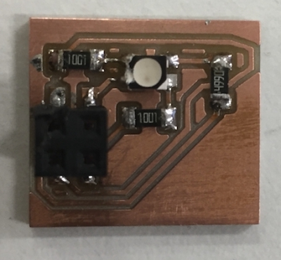
I used following components:
- 2x 1000 ohm resistor
- 1x 499 ohm resistor
- 2x2 header (female)
- RGB led
Next it was time to program the board.
Programming the board
I used the following pins for the RGB board. Picture is from Atmel data sheet (copyright by ATMEL):
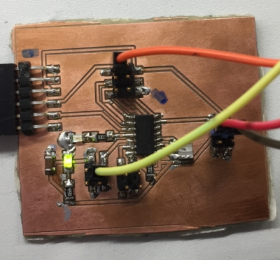
To use these pins, I connected cords between the RGB LED board and Mainboard as seen bellow:
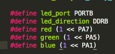
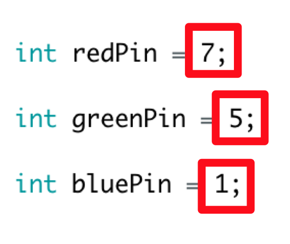
I change these pins from Neil´s code as seen bellow:
Then I sent the code to my board to test it. However I didn´t get the board working. After trying few more times, time run out from this week, and I decided to come back to this week´s assigment later
Comming back to fix stuff
I wasn´t sure if my problem was due to code or due to electronics, I decided to began problem solving by remaking RGB led board. Layout of this redesigned board can be seen bellow: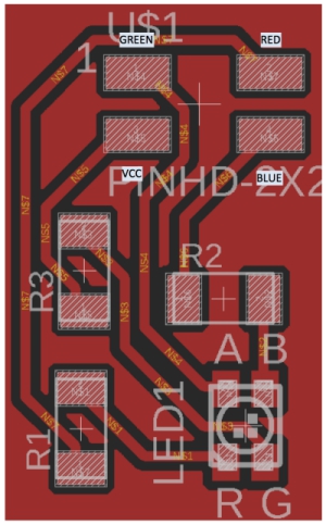
The Schematic is same as before:
The board can be seen bellow:
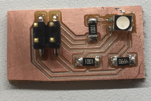
When the board was ready, I verified that there were no short in the board. Everything was fine. Therefore, I connected the cord and labeled them to easier the connection process:
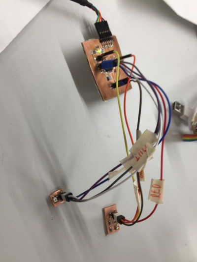
Then I connected it to mainboard as before:
Next it was time to do the code. After trying to learn C, I decided to use Arduino to simplier the process. I ask help from Megumi to create code for RGB-leds, she directed me to her 3D printed Jack-O-lanter project where I took her RGB led code (seen bellow) for modifications.
To make this code to work with my board, I changed pin numbers to correspond my board´s pin numbers. To do this, I had to use picture seen bellow to convert my attiny ports (green boxes) to arduino ports (grey boxes). Relevant port converting rows are squared red:
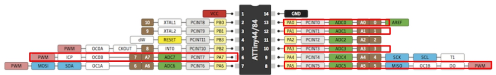
Therefore, I used following arduino port numbers for my attiny ports:
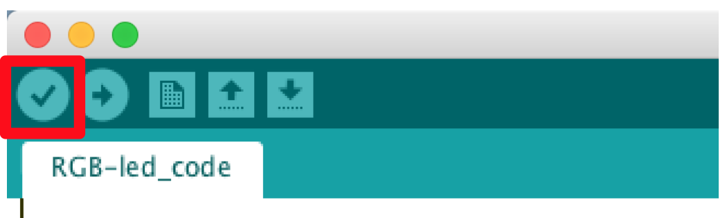
I saved the code and compiled it in arduino by clicking "Compile" (red box):
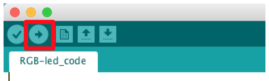
Then I uploaded the code to board by clicking "Upload" (red box):
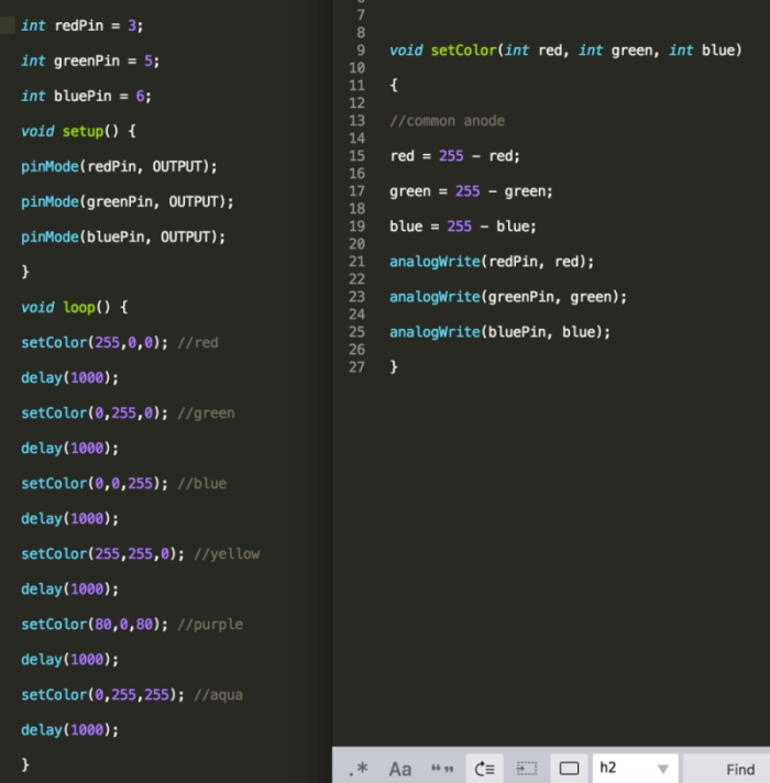
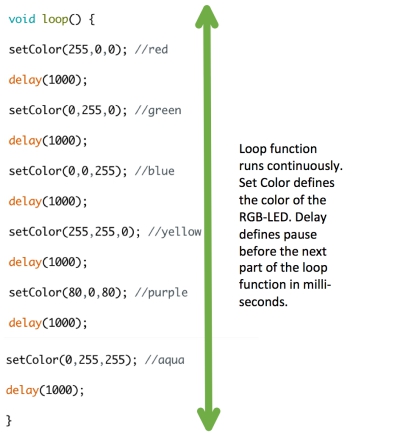
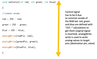
The code was working. The code changed the color of RGB led time to time. Here is a VIDEO about the board in action. Whole arduino code and explanations of each parts can be seen bellow:
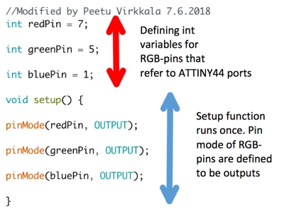
Due to my tight schedule, I decided to update the code in future for my final project to be able to change LED colors
with light sensor board input. For this week, this basic code should be enough.
