Assignment 13
18.4.2018
Topic: Interface and Application Programming
Goals of this week:
- Write an application that interfaces with an input or output device that you made (Individual)
- Compare as many tool options as possible (Group) (LINK)
Learning more about the topic
I began this week on Thursday by rewatching the global lecture. I made following memos about the lecture:

Then I looked through previous years interface assigments from Fab Lab Oulu. In many of them, people had used Processing,
After learning more about it, I decided to use it for my interface project. Processing is a programming language where every
project (sketch) is actually a subclass of the PApple, formerly subvlass of Java´s built-in Applet. All additional classes defined
in Processing are treated as inner classes when the code is transformed into Java before compiling the code. It was orginally designed
for visual designers and creators who are not familar with computer programming. It can be used for example to create generative art,
computer games and user interfaces.
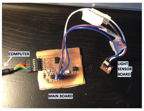
I decided to create user interface for my Week 11 light sensor-mainboard
system which changes according to changes in light sensor.
(input of the board I will be using computer to visualize the data. Picture of the board system can be seen bellow:
I watched basic Processing tutorial and looked through Yrjö´s interface assigment.
With the knowledge I got, I created following paper sketch of my UI which contains a box
that changes its size according to voltage value in one of Attiny44´s pins and exit box
which can be used to close the program. The voltage value I´m measuring is voltage difference
that occurs over photodarlington sensor on my light sensor board. The paper prototype can be
seen bellow:

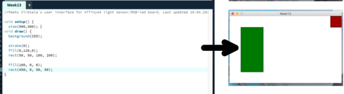
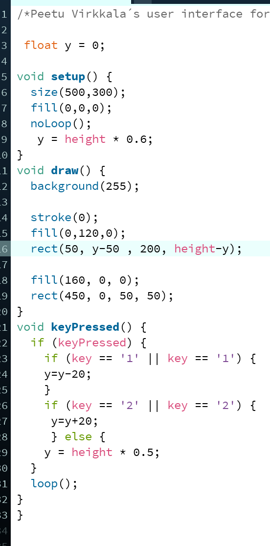
According to this sketch, I created same UI in Processing. This was achieved
by using setup and draw functions as seen bellow:
- void setup = Setup function that run only once when the program is launched (Creates white canvas)
- void draw = Draw function that is happening constantly (Draws green and red rectangles)
- fill defines filling color with RGB input value
- rect defines rectangle according to given x,y cordinates and corresponding lenghts
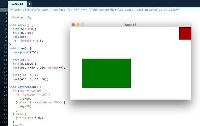
Then I edited the code so that I was able to move the green box up and down just by clicking
directional arrow keys up and down.
- void keyPressed = Function to identify keyboard presses effect to program (UP-arrow =rectangle grows, DOWN-arrow = rectangle shrinks)
When this was done, it was time to start really think how I could get my user interface to show values from my
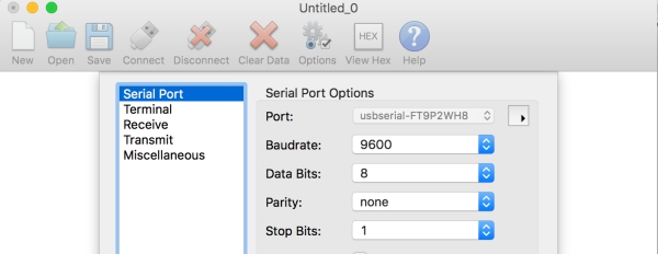
microcontroller on the computer screen.To easier the process, I opened Yrjö´s code from this week and changed
his serial port to my serial port by changing the following line of code in his code as follows:

(Yrjö´s orginal serial code line)

(My own serial code line)
Next, I tested if the UI/serial port connection was working. However, I wasn´t able to get mainboard´s
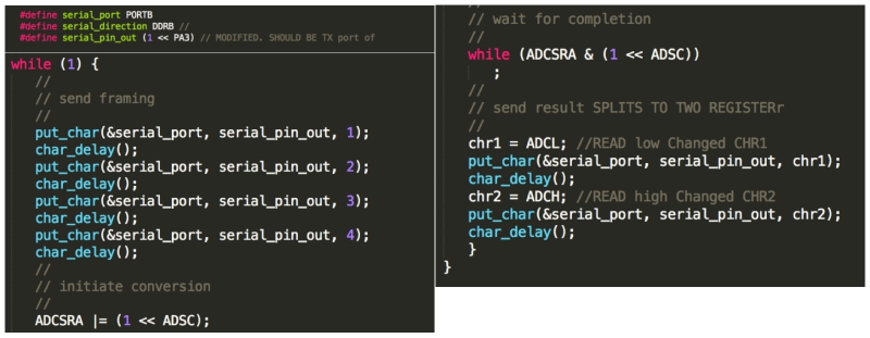
serial port to intereact with the UI: when I run it, it just crashed. I began problemsolving by checking
the code of the board to see how it was communicating with a serial port. Everything seemed to be fine.
Serial pin was defined correctly to be PA3 and the code was wrote to send characters 1,2,3 and 3:
To verify that my computer was able to find
the board, I downloaded CoolTerm-program which visualizes data coming from serial ports.
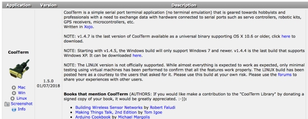
In CoolTerm, I choosed the port which my board was using and clicked connect. However, I didn´t get any data to my computer.
This revealed that there was something wrong either in my board or in my programmer.
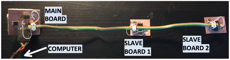
Because my Input-week wasn´t interacting with a serial port and I didn´t have time to find the problem, I decided to use boards which
I created during Networking and communication week because they were interacting without any problem with a serial port. I´m using
output of the board system. Picture of this board system can be seen bellow:
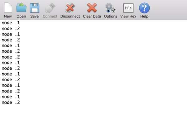
When these boards are connected to serial port and I click "1" on keyboard, Serial feed shows: Node 1, and when I click "2"
on keyboard, serial port shows: Node 2.
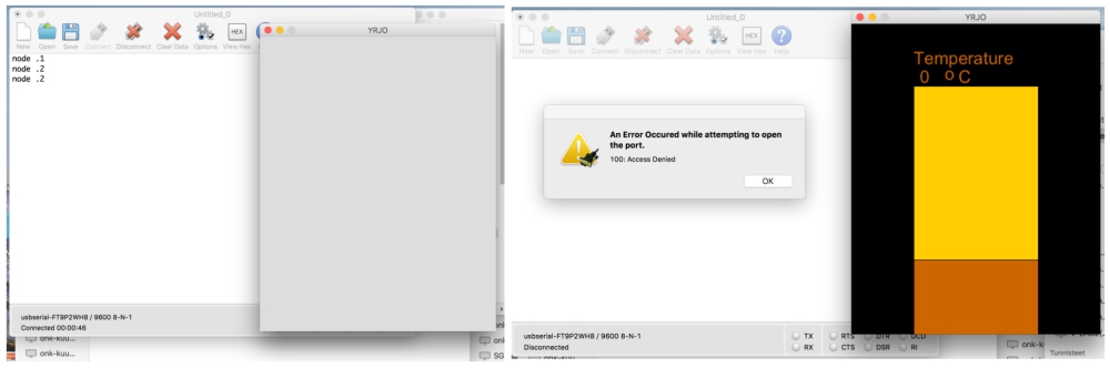
To test that Yrjö´s program was interacting with a serial port, I clicked run and saw that the program oppened. Therefore,
I deducted that it was interacting with a serial port. I learned also that two porgrams cannot use same serial port at the
same time as seen in picture bellow: (Left: Coolterm runs fine, Process crashes, Right: Coolterm cannot run, Process runs fine)
Creating my own UI code
Now that I had tested that my boards were interacting correctly with Processing, I continued to edit my orginal code to have
similar structure as yrjö´s code. However, when I run the code, my keyboard inputs didn´t got led´s flashing as they did when
I opened the serial trafic in Coolterm. After discussing with Marta about the topic, I learned that I had to first write these values to
boards in my code before I was able to communicate with the boards. To do this, I used similar my_Port.write command as Marta in
her code:
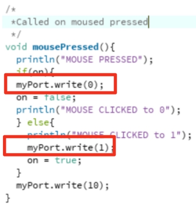
I added my_Port.write structure to my code in keyPressed function as seen bellow:
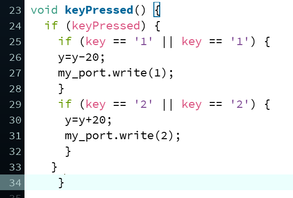
When this was done, I got my boards led´s to flash when I clicked "1" or "2" on keyboard. However, the led´s didnt flash as
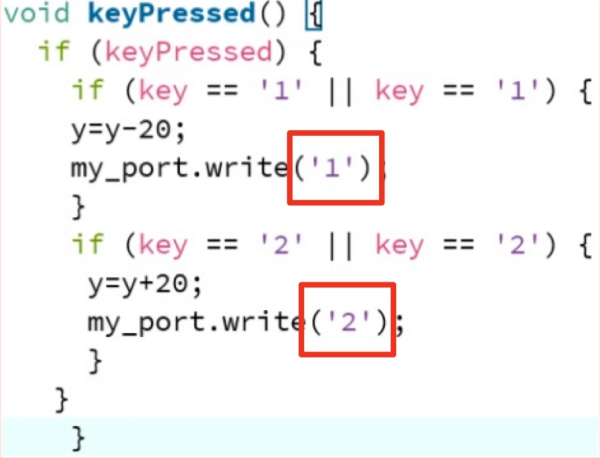
they were flashing when commands were given in CoolTerm. To fix this, I added `` marks around the numbers in my_port_write
functions as seen bellow to make processing to understand that they were letters, not numbers. When this was done, the boards
were flashing as during the Week14. At first, I was sending an int value, but after this change, I was sending ASCII representation
of the number which my Mainboard´s program understood
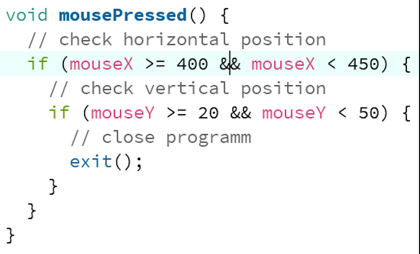
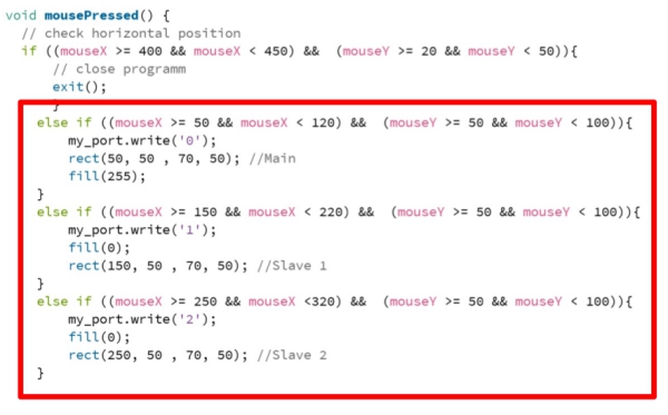
Next I finished the exit button. After googling a while, I found this tutorial and decided to use it to create interactive exit-button
as seen bellow:
- void mousePressed = Function to identify mouse click effect to program in some specific area (Area to exit() the program defined)
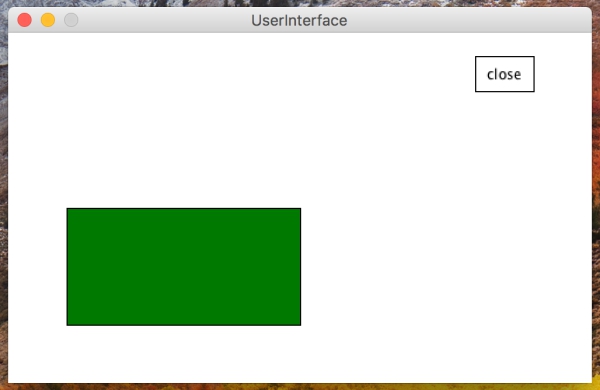
When this was done, my program was ready and I had finished this week´s assigment. The end result can be seen in this VIDEO.
Final code can be seen bellow:
User Interface generated from this code can be seen bellow:
Update: developing the UI further
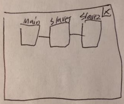
After getting feedback from this week´s assigment, I decided to change my UI to fit better to my networking
and communication board system´s needs. With this new UI, I want to visualize led flashing of the boards´
leds when number keys '1' and '2' are pushed. When the boards send message NODE1 or NODE2 to computer serial
port, I want to visualize this message with a flash on the screen. Addition to this, I want to create buttons
on the UI, which I can click to get same effect as by pushing the number keys `1`and ´2´. Paper sketch of this
user interface can be seen below:
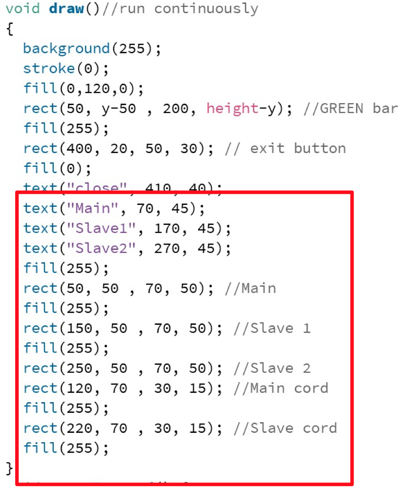
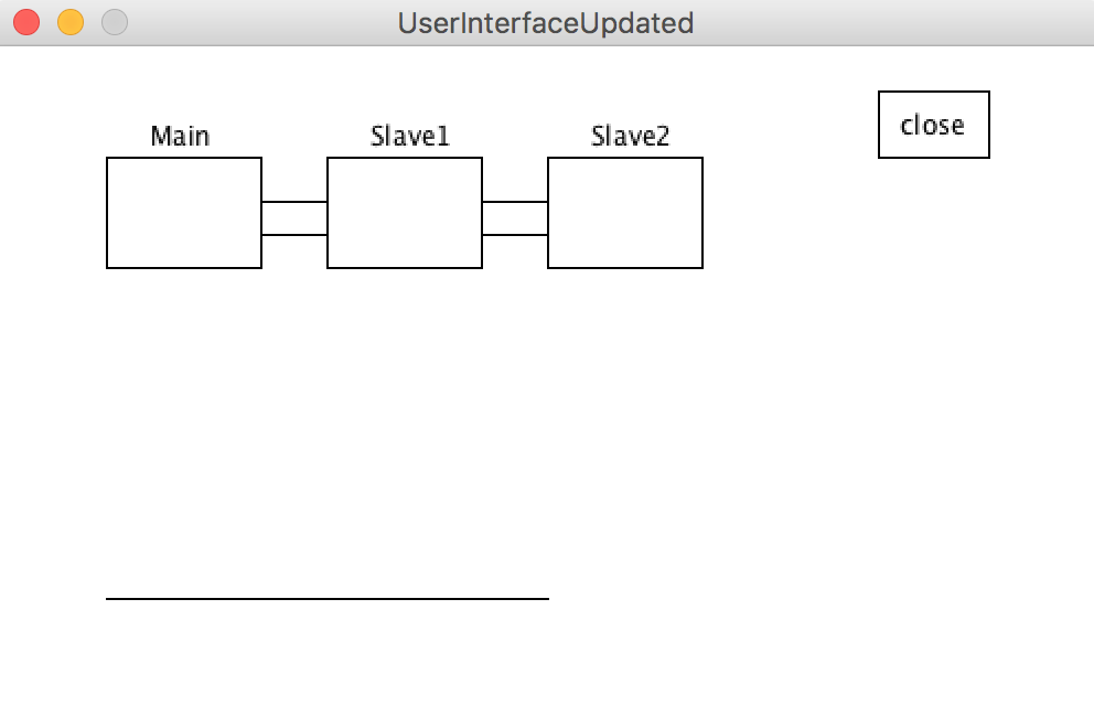
First I updated the draw function to draw all of the boxes, "cords between them and texts. Additions are rectangled red:
Finally I updated mouse pressed function by adding click areas around new boxes and flash effect. Additions are rectangled red:
The UI was now updated. Slave 1 and Slave 2 button was working properlly whereas Main button was not working due to problem in
the board. Here is link for the VIDEO. Bellow is a picture of the UI:
EXTRA:Requirements to send data from microcontroller to computer
To easier the process to do this week´s assigment, I wanted to learn requirements to send data from microcontroller to computer.
The process can be divided to 3 areas:
- Getting data from the environment to microcontroller
- Sending this data to the computer through serial port
- Reading this data on the computer
To understand these thinks from the basics, I began to looking this process from the start.
Getting the data from the environment
First I learned how data is stored in the board and how digital-analog converter works. According to this and this video,
I made following conclusions:
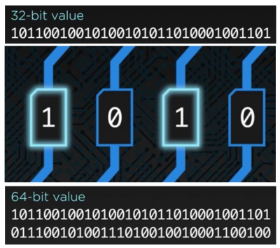
- Microcontroller "things" data as a bits.
- 1 is ON and 0 is OFF. 1 is achieved always when current is max and 0 always when current is minimum (0).
- Bit can be 0 or 1 randomly if the current is between some specific borders.
- Computers usually read 16,32 or 64bit parts at time.
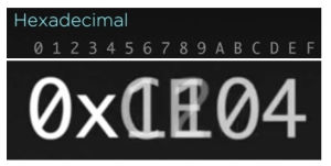
- Heksadesimal goes from 1 to F (15) and makes it easier to write bits to the code.
- 0x---- is typical way to decribe heksadesimals in code.
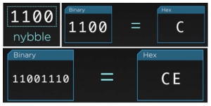
- 4 bits are called "Nyble" and it can be resembled with one heksadesimal.
- 8 bits can be resembled with two heksadesimals.
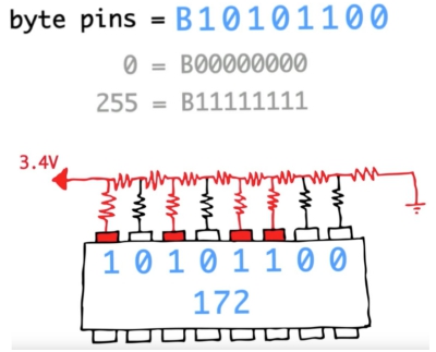
- Byte pins number dives numbers (0 or 1) to microcontrollers pins. This number can be converted from normal 10-desimal number.
- According to this number, spesific current between min and max is achieved.
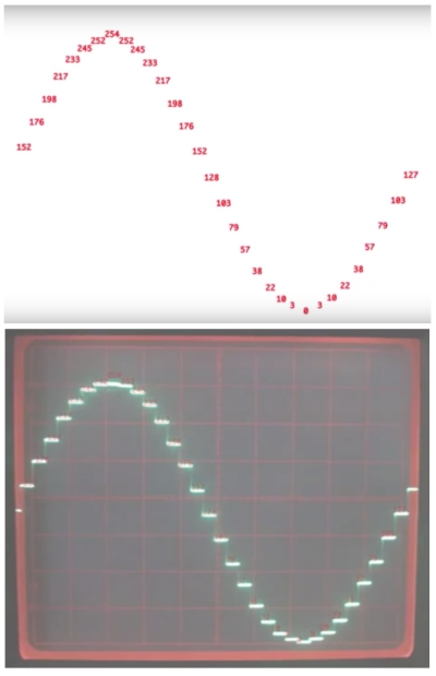
- Each of these specific currents are drawn next to each other to form analog curve: Digital signal is changed to analog signal.
FILES made/used THIS WEEK

This work is licensed under a Creative Commons Attribution 4.0 International License.