Assignment 14
26.4.2018
Topic: Networking and Communications
Goals of this week:
- Design and build a wired and/or wireless network connecting at least two processors (Individual)
- Send a message between two projects (Group) (LINK)
Learning more about the topic
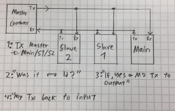
I began this week by watching Global lecture. According to stuff learned from the lecture, I created following picture to help me
to understand the process between Master computer, mainboard and slaveboards:
I had still few project from last week to finish, so I decided to do this week´s assigment simplistic way. Therefore, I decided
to create three boards similarly as in Neil´s hello.bus-example. This board system
flashes first all the leds when the user types 0,1 or 2 and then
the led with corresponding number (0,1 or 2).
Drawing and milling the boards
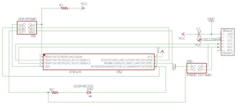
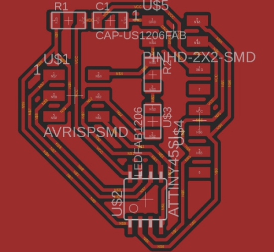
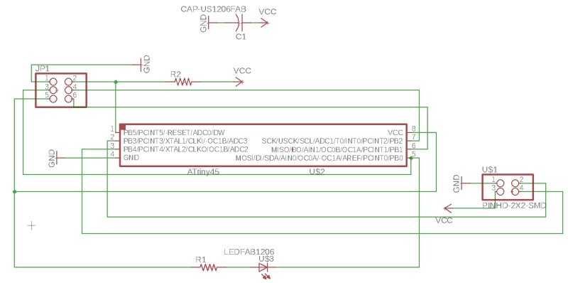
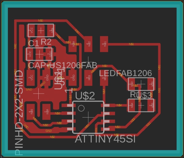
The process went forwards in similar way as previously. I created Mainboard and slave board schematics, modified them in brb. mode,
and created interior and traces files which I then edited in Fabmodules:
Mainboard:
Slave board:
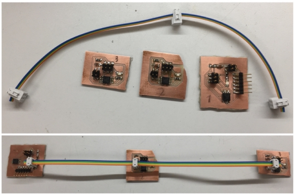
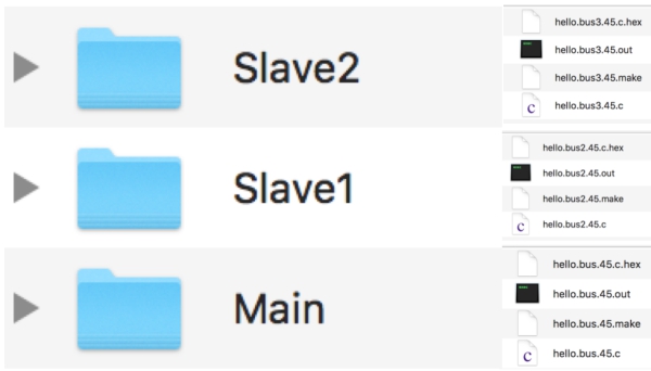
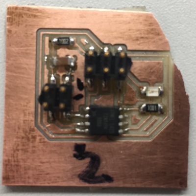
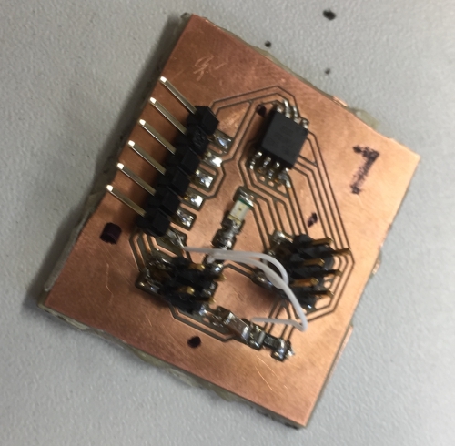
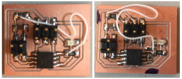
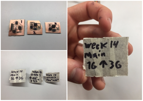
Then I sent these files to the Roland SRM-20 milling machine, milled the boards and created jumper cable for them. Finally, I numbered
the boards from 1 to 3. 1 is Main and 2 and 3 are Slaves:
Sending the code to the boards
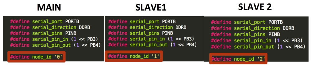
I downloaded Neil´s hello.bus code and make-file for the main board. I began by creating 3 different codes: one for main, slave 1 and
slave 2 board. In each code, I defined different node_id as can be seen bellow. For the main board, it is 0, for the slave 1, it is 1
and for the slave 2 it is 2. I also created individual make files for each of these codes by renaming Neil´s orginal make-file.
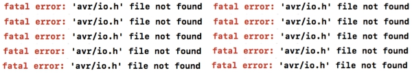
However, when I tried to create .hex and out files with a command "make -f ´makefile name´ make" on my Mac, I got same error as during
the previous weeks: "avr.io.h not found".
After trying to fiqure the problem for few hours, I finally found the solution together with Ari. First of all, I had been concentrating to
the wrong problem. Process where avr.io.h problem occured was not a correct process to create .hex and .out files. Instead, when I used
right command structure: "make -f ´makefile nameán .make" I got error pointing out the problem in spaces in my makefiles. Neil´s makefiles
had spaces instead of tabulators. Terminal was expecting tabulators instead of these spaces in the code. Therefore, I had to replace these
spaces with tablutators.
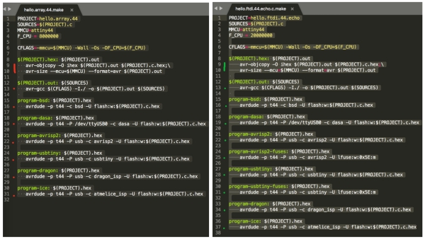
If I tried to change these spaces to tabulators in Xcode, the spaces remained. However, when I opened the makefiles in Sublime Text Editor
and changed spaces to tabulators, changes were saved. (Left: Neil´s make file with spaces, Right: Edited file with tabulators)
Now, I was able to create .hex and .out files!
Then I had problems to create fuses but figured out that I didn´t have to create them for my boards. Therefore, I went to the next step:
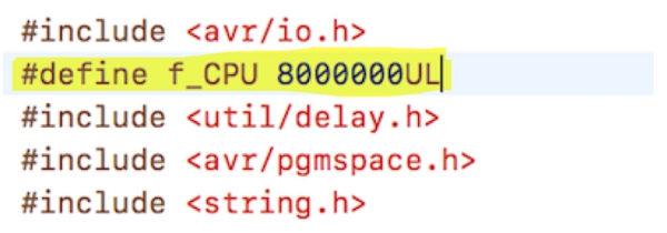
program-usbtiny and was able to program my main board. I added code line highlighed bellow as recomended by Behnaz to my main and slave
board c-codes:
I managed to send code to my Main board but I couldn´t send code to the slave boards. After inspecting the boards, I noticed that parts of them
weren´t cut properly:
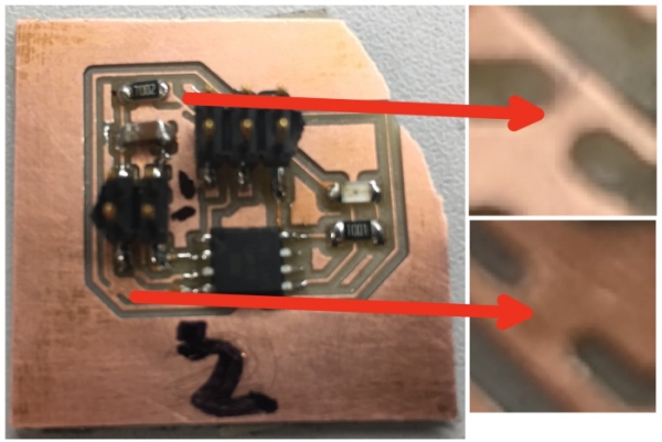
I used scapel to cut these parts properly. Still, the slave boards were acting strangly.
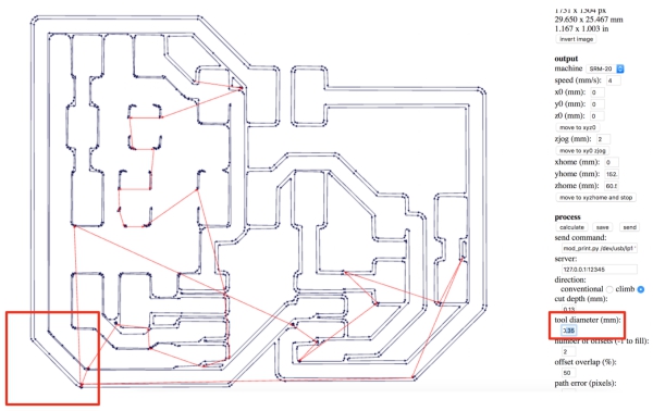
However, the problems continued. Therefore I decided to mill and solder new slave boards. When I was milling new boards, I noticed that the
problem was due to traces-file I created in Fabmodules. Gaps between problematic lines were too small for Fabmodules with a 0.4mm tool diameter
so it didn´t drew the lines to milling-file. To fix this, I used 0.35mm as a tool diameter value even thou I was using 0.4mm tool and the line
was now drawn correctly in Fabmodules:
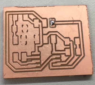
I milled slave boards with these settings. The end result was a success:
Then I soldered the boards again and tried to program them. However, I still couldn´t program the boards. After few hours of problem solving, I
noticed with a help of Antti and Jari that I was lacking One VCC and GND connection from the Main-board and one VCC connection from the slave
boards.
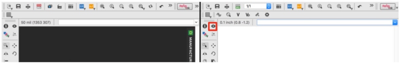
I noticed these problems by having both schematic and board view next to each other on the screen and by using "Eye" tool and clicking GND and VCC lines.
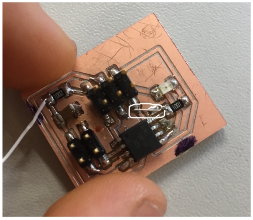
I fixed the mainboard by creating jumper cords to connect following GND and VCC lines together from areas rectangled white:
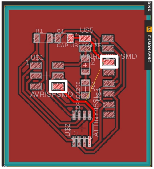
GND lines to connect together:
VCC lines to connect together:
Lines connected together:
Then I fixed similarly VCC problem in slave boards:
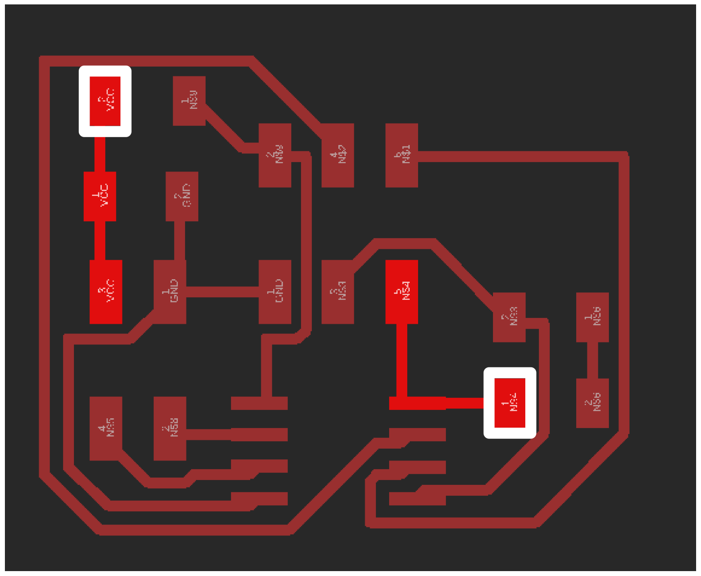
VCC lines to connect together:
Lines connected together:
When this was done, I was able to program Main and Slave 2 boards. However, Slave 1 board couldn´t be programmed. After a few hours of problem solving,
I found a reason for the problem: The jumper line had snapped inside the plastic cover:
I fix this by creating new jumper cord. After this, I was able to program the board.
Getting the boards to work
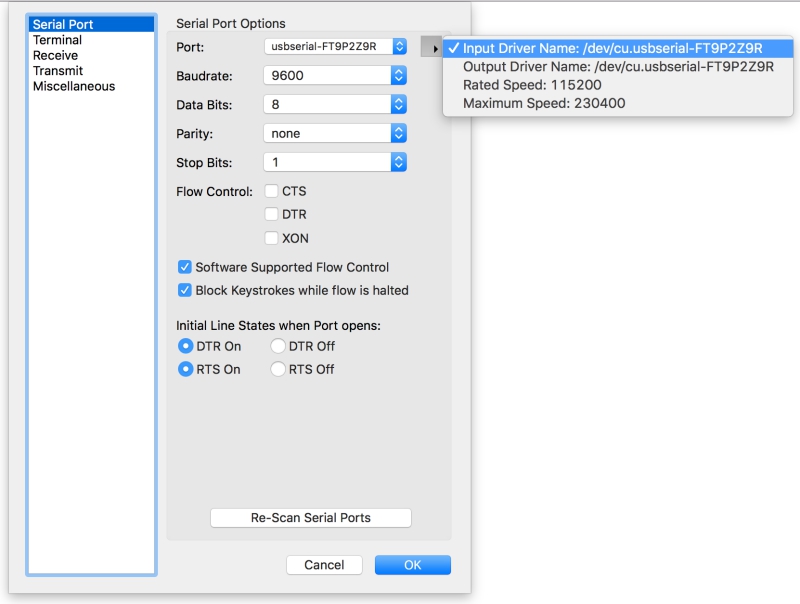
I connected the boards to my computer and used CoolTerm to inspect serial port trafic. First I opened options:

From there I chosed my connected board as an input device and cliked ok:
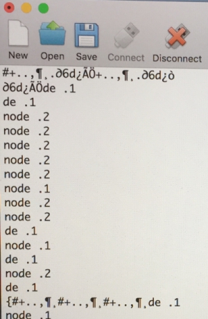
Finally, I clicked connect to see serial trafic from the device:

By clicking number 1, 2 and 0, I managed to get serial communication working. Node 2 was working fine but Node 1 gave strange messages time to time and
Node 0 didn´t respond. What should happend is that when I hit 0,1 or 2 on keyboard, I get notification to serial software (Node 1, Node 2 or Node 0), all
the LEDs in all 3 boards flash once and the LED in the numbered board (Main = 0, Slave 1 = 1, Slave 2 =2) would flash up for a few seconds more. This was
not happening.
LINK TO VIDEO
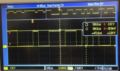
To fiqure out the reason for the problem, I used Tektronix AFG3021C oscilloscope to measure the signal. Bit delay time was same, 100ms as in the code:
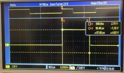
However, FTDI cable was giving 5V to the Main-board but receiving only around 2.80V back. This may lead to situation where the computer defines sometimes
randomly between 0 an 1.
I thought that the problem may occur where the boards send their tx-output. There may be a situation that the boards aren´t taking turns.
I will check this problem in future if I have time but from this time, this should be enough for this week. I have managed to design and
build a wired and/or wireless network connecting at least two processors.
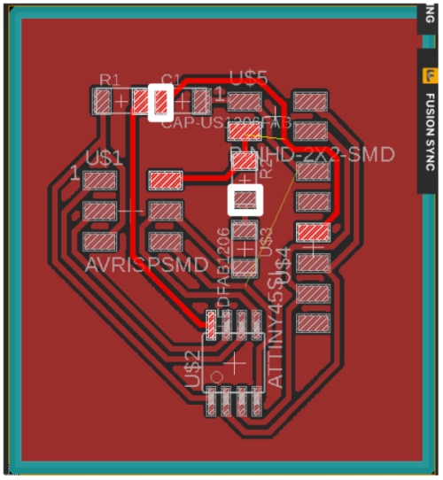
EDIT: Problem partly solved
When I reviewed my main board, I noticed that I had soldered my VCC jumper to wrong place. Following is the correct position marked white.
When this was done, Slave 1 and Slave 2 were working without any problem as seen in this VIDEO (I added few instances of flash(); to the end
of the code to show the effect better). The main-board was still not flashing led and I couldn´t command it. This may be due to some soldering
problems or the same milling problems which I had with the slave boards. If I have time and interest in future, I redo the Main-board and see if
it helps the situation.
EXTRA: Marking the boards
I decided to create simple marking method for my boards. I have had sometimes problems to identify the right pins and connect the cords
correctly, therefore I put tape-signs under my boards which includes:
- Project week
- Board name
- Where relevant ground pins are located
I also marked ground pins on the top of the board with a permanent marker:
FILES made THIS WEEK

This work is licensed under a Creative Commons Attribution 4.0 International License.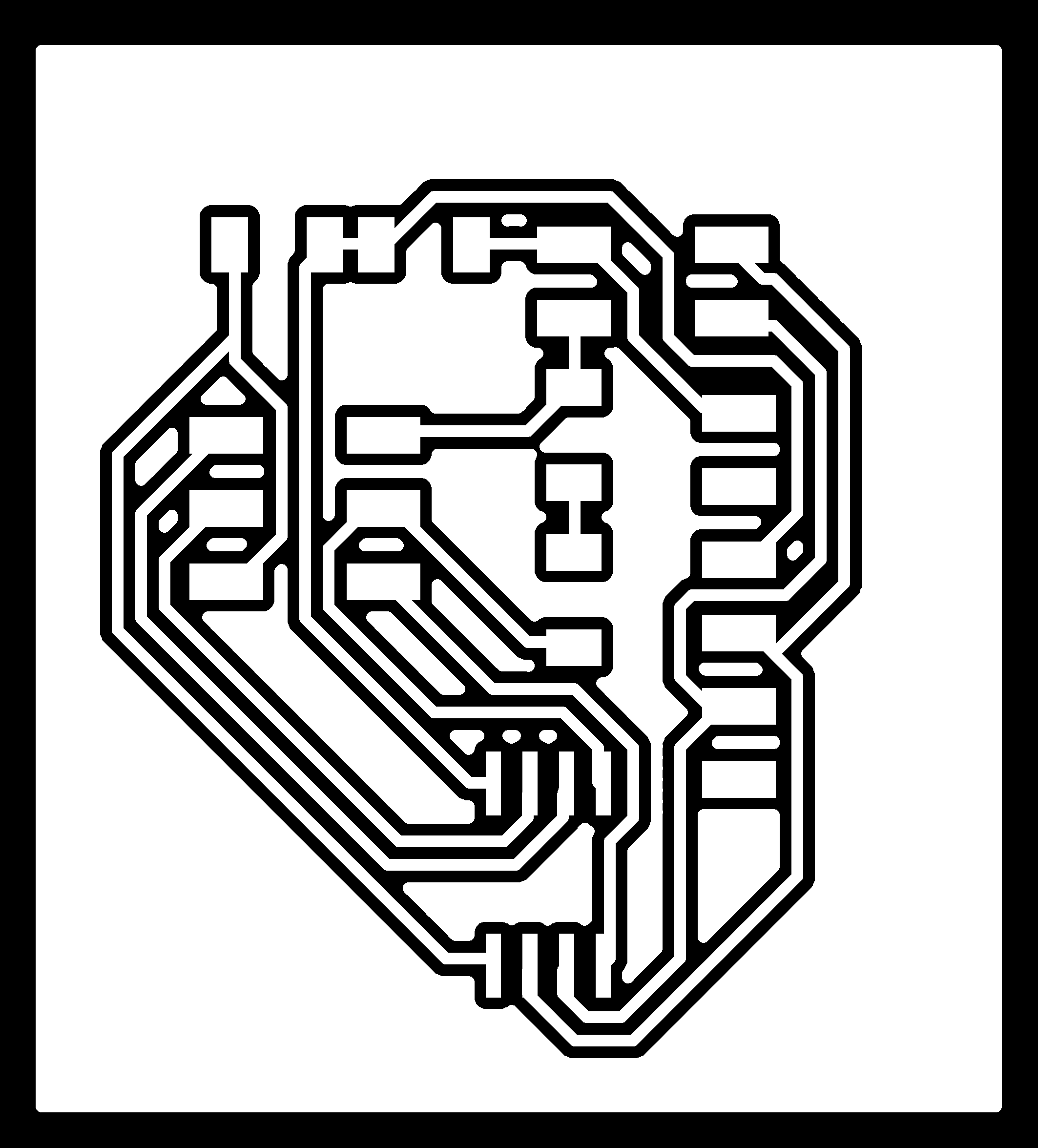