Assignment 4
07.2.2018
Topic: Computer controlled cutting
Goals of this week:
Laser cutting
- Explain how to parametrically design files (individual)
- Show how to make press-fit kit (individual)
- Include design files and photos of finished project (individual)
- Characterize your lasercutter by making test parts that have varying cutting settings and dimensions (group) (LINK)
Vinyl cutting
- Explain how you drew your files (individual)
- Show how you made your vinyl project (individual)
- Include design files and photos of finished project (individual)
I began this week by deciding what to cut with a laser cutter and a vinyl cutter. Then I prepared my cutting files and cut my designs.
Finally, I tested my cuttings and did my part for this week´s group assignment.
Deciding what to cut with the laser cutter
At first, I got an idea about action figure press-fit kit. With this kit, the user could create action figure which would look like a
mix of Danbo (Yotsuba character) and Sackboy (LittleBigPlanet character). Here is reference picture of these characters:
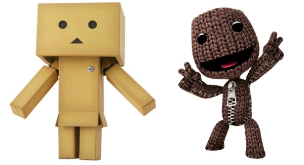
(References for orginal pictures: Danbo and Sackboy)
I wanted that my figure would be cubic like Danbo but have still multiple changeable mouths and hats as pieces like Sackboy has.
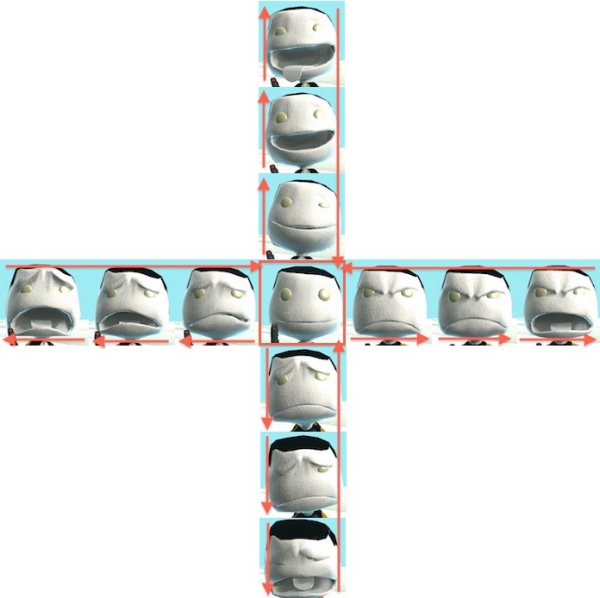
Sackboy is a game character, which is able to show different emotions according to player´s inputs on the PlayStation controller
D-pad as seen below. For example, 2nd emotion from up can be seen when the player clicks D-pad twice upwards whereas leftmost
emotion can be seen when the player clicks D-pad three times to left:
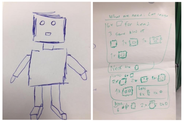
Hence, I planed that action fiqure would have following features:
- Changable mouthpieces for different emotions
- Moving arms
- Moving legs
Next, I made few sketches of the figure. Here are some brainstorming sketches:
I used Fusion 360 to visualize prefered end result with the simple 3D model:
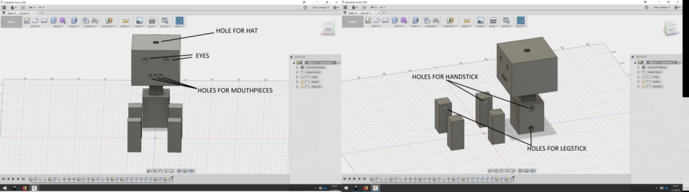
Simplifying the design and designing the model in Fusion 360
In our lab, we have two Epilog laser cutters. I decided to use Epilog Laser Fusion 75W CO2 because I had previous experience
with it. Laser cutting with our Epilog laser cutters shouldn´t be problematic as long as I remember to:
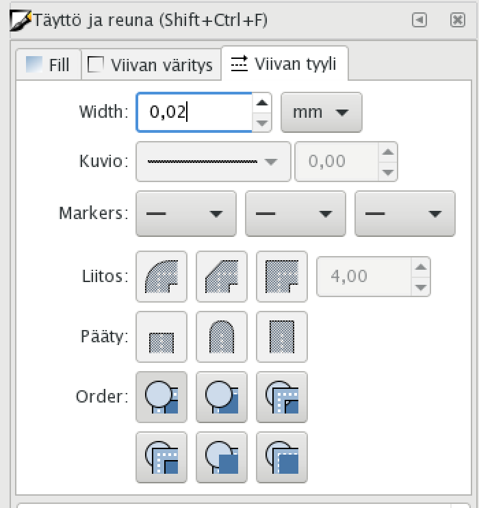
- Use line thickness of 0.02mm for the lines which I want the laser to cut
- Use other than 0.02 line thickness for the lines I don´t want to cut or which I want to raster
- Change laser cutting speed and power according to material which I use
- Use laser machine safely with safe materials
Related to my action figure press-fit kit, I noticed that my figure idea didn´t fill this week´s assignment requirements. Therefore,
I decided to create much simpler parametric construction kit. This kit would include only similar parts. Then, if I would have time
after this during this week or in the future, I could learn more by creating my action figure press-fit kit.
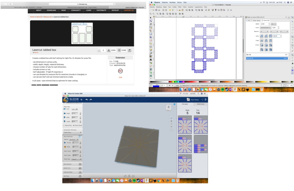
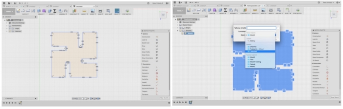
I tried first construction kit add-ons for Inkscape and Fusion 360 but got informed that they couldn´t be used for this week´s assignment.
(Left: Lasercut addon for Inkscape, Right: Addon in practice and Bellow: Slicer addon for Fusion 360)
I had some problems making parametric designs in Fusion 360, but step by step, I managed to move forward
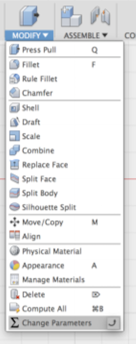
To create parameters, I chosed Modify>Change parameters:
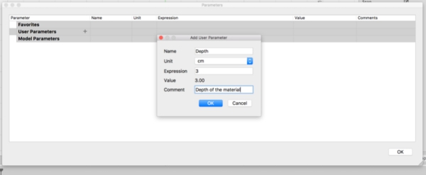
I began by creating a depth parameter:
Then I created other parameter which I thought that I needed:
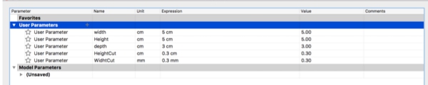
I tested Width-Height parameters. They were working:
Even when I had learned to create parametric for my measurements, I had some problems to define my parameters. However, after a while,
I was able to mirror my parametric design from one side of the box to other sides of the box:
Creating more parametric lines to sketch
When I had finished one side of the design, I used mirroring function to mirror my sketch to other side
Top left: Testing extruding the design, Top right: Changin parameters, Bottom left: -II-, Bottom right: testing extruding the design
To fix the problem, I edited the sketch by changing some of the parameters for dimensions
However, I had constant problems to edit some of my parameters after I had defined them: changing their values broke the whole design.
To fix this, I decided to use only one changing parameter "DEPTH" and describe all other parameters with it. Even that it worked at first,
The design always broke when I tried to scale it.
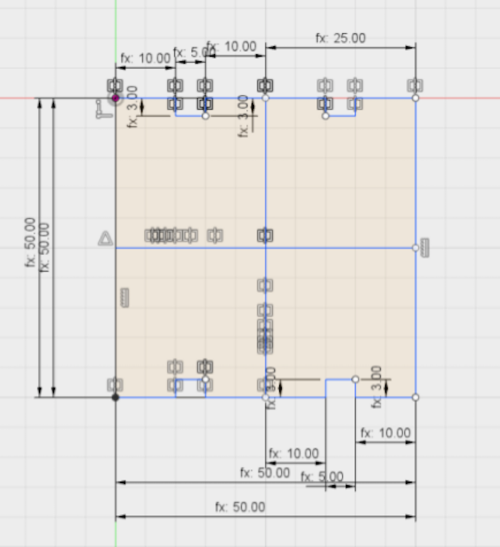
Finally, after many failed attempts, I managed to create a parametric model by using constraints and parameter only for the DEPTH.
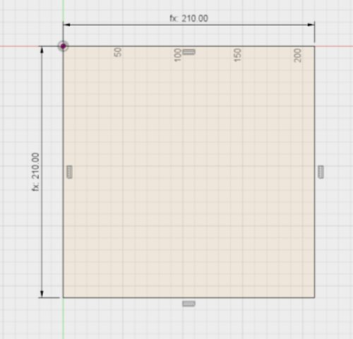
I did this by starting from scratch:
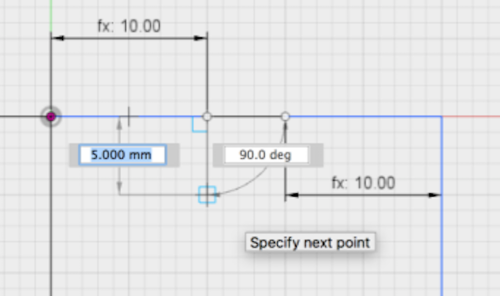
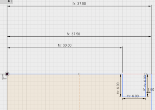
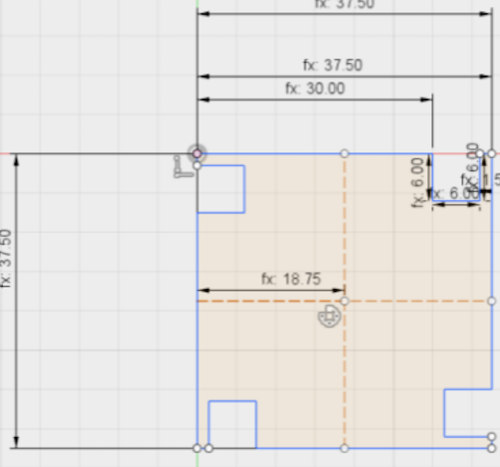
I created big and small boxes by using parameters defined with DEPTH and used Horizontal/Vertical constrait
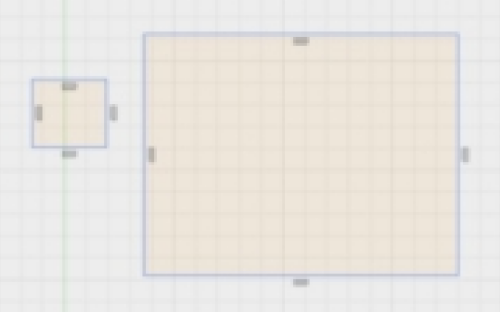
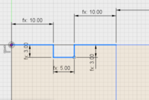
I used small box to cut pieces from big box and used Perpedicular constrait for the edges
Finally, I used Equal constrait to make mirror parts equal
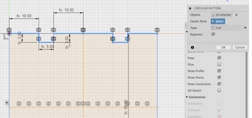
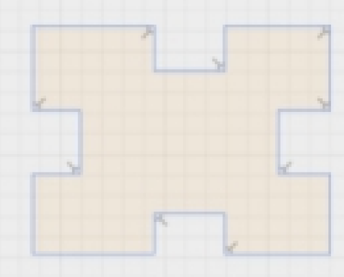
By dragging the shape, I could see that everything was working fine
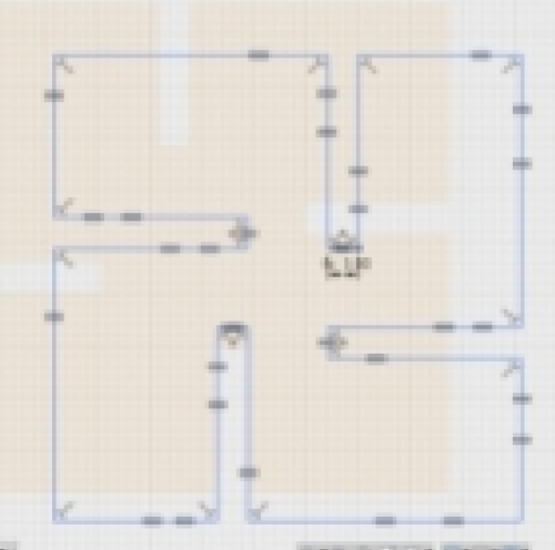
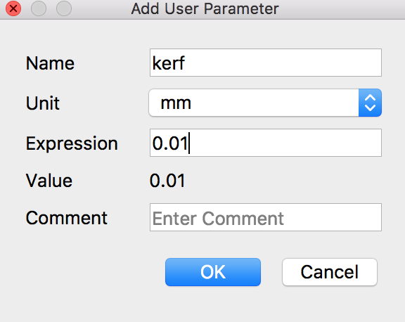
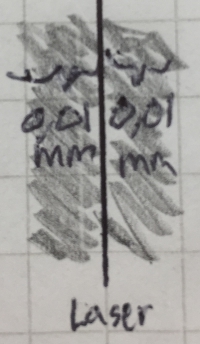
To take into the account kerf - area which the laser burns around the cutting line, I created kerf parameter as can be seen below.
0.01mm value was chosen according to test we made during this week´s group assigment
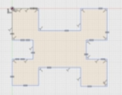
Then I used this parameter to my measurements, like gap width, by adding it twice to measurements (because laser burns material on both sides of the cutting line):

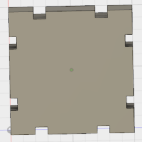
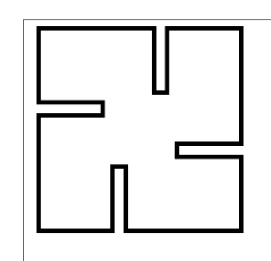
Finally, I tested that the model was still scalling correctly when the DEPTH parameter was changed.
Left: Changed "DEPTH" value. Design didn´t break Right: I saved the design as a PNG.
My design was now ready for Fusion 360. Next, I prepared it for laser cutting by exporting it as a PNG. to Inkscape.
I changed the linewidth to be 2mm so that the laser cutter would cut it along the lines.
I copied it so that I had 2
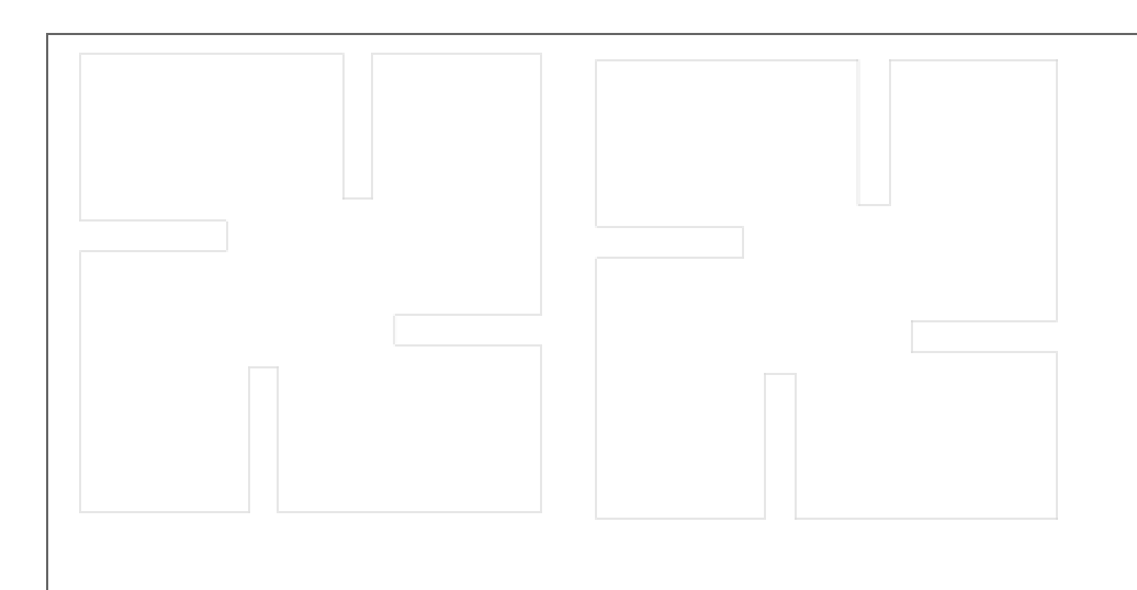
Then I saved it again as a PDF. to be able to use it with Epilog Laser cutter.
Using Epilog Laser Fusion 75W CO2
Epilog laser cutter is used as follows:
1. Transfer the file to the computer connected to Epilog laser cutter
2. Open your project as a PDF.
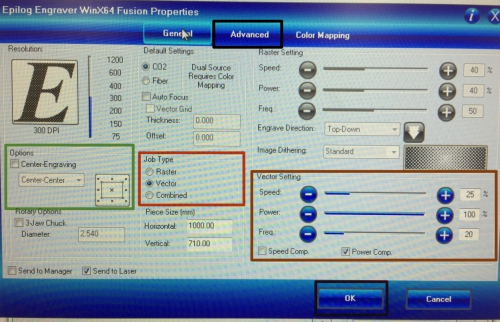
3. Choose to print the pdf and choose Epilog Engracer WinX64 as a printer. Following screen is opened:
The settings I used and edited in this individual work and/or in group work were:
---------------------------------------------------------------------------------------------------------------------------------------------------------------------
- Center-Engraving off. If it is on, laser starts the cutting procedure from the center point (Green box)
- Job type. Vector: laser only cuts, Raster: laser only raster and Combined: laser cuts and rasters. I used Vector (Red box)
- Vector Settings. Speed changes laser moving speed, Power changes laser power and Freq changes laser frequency. I used automatic
values set to my chosen cutting material (Brown box)
- Advanced button to go to advanced settings (Upper black box)
- Ok button to accept changes and close the window (Black box bellow)
---------------------------------------------------------------------------------------------------------------------------------------------------------------------
4. Click Advanced button to go to advanced settings. Following screen is opened:
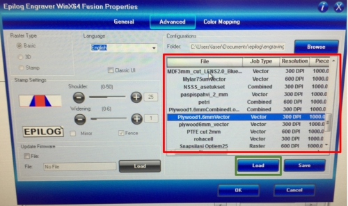
5. Choose prefered material from ready made or create your own (Red box). I used MDF2mm_cut_LENS3.0
6. Click Load button (Green box) to load choosed material settings to the General screen
7. Click General button left next to Advanced button, and check that your settings are correct
8. Click Ok button to accept changes and close the window.
Next, set up the laser cutter physically
Epilog laser cutter is mainly controlled with the following user interface:
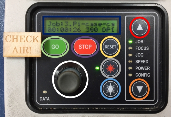
I used mainly following functions with the cutter:
- Joystick to move the laser/machine and to interact with the screen (Grey circle)
- Go button to save settings and to start the cutting procedure (Green ellipse)
- Stop button to stop the cutting procedure if something went wrong (Purple ellipse)
- Reset button to cancel the cutting procedured which is stopped (Yellow ellipse)
- Red laser button to get visible laser (Grey circle)
- Up button moves mode between CONFIG-JOB upwards (Red circle)
- Down button moves mode between CONFIG-JOB downwards (Orange circle)
Setting up the laser cutter goes as follows:
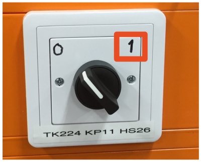
1. Ensure that the vacuum and air assist connected to Epilog are on. In my lab, the vacuum is on when switch next to laser cutter
is turned into "I" position (red box direction) as seen below:
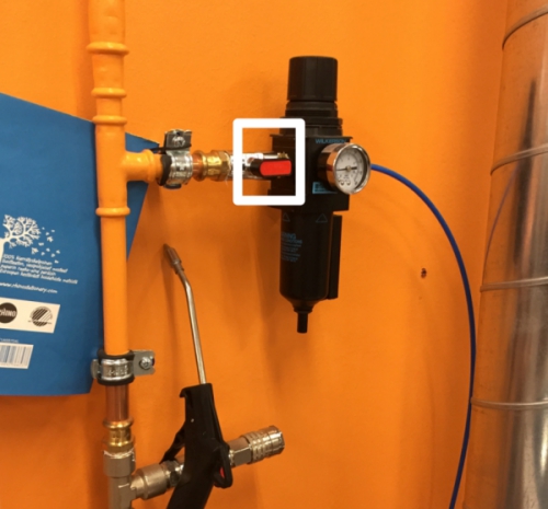
The air assist is on when the valve next to laser cutter is turned as can be seen in the white box bellow:
2. Put your material inside the laser cutter. Ensure that the material is not bended
3. Use FOCUS and JOG modes with joystick to define cutting origin. Save your origin by clicking joystick in Focus and JOG mode. (Use
measuring triangle when measuring JOG).
4. Go to JOB mode and check from the screen that you are cutting the right file
5. Click Go to launch the cutting procedure
6. Monitore the cutting until the cutting is ready
7. Wait few minutes and open the printer cover to take your cuttings away
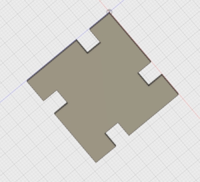
By following these procedures with my own design, I got following end results:
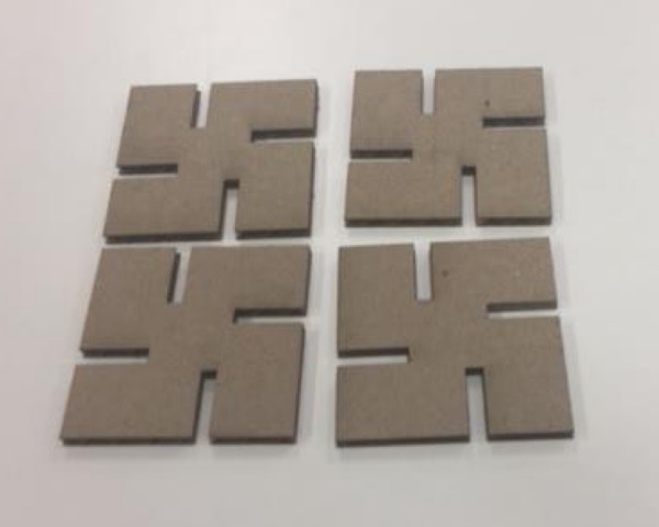
Here is the design used as it meant to be used - as a press-fit kit. Everything was fitting together but connections were
bit loose.
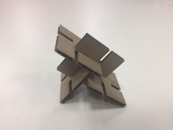
Later on I learned that loosness was probably due to laser kerf. Our laser cuts around 0.01mm cardboard from both sides of
the cutting line. I have to take this into account in the future.
Deciding what to cut with the vinyl cutter
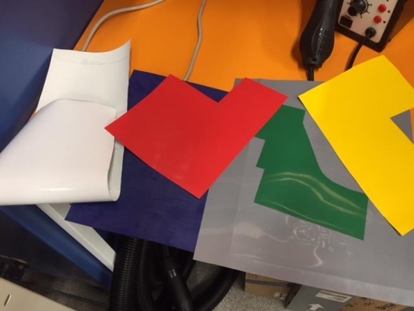
When I heard that there is a possibility to make prints for clothes with the vinyl cutter, I knew that I wanted to try some of my clothes. For
the cloth vinyl cutting, my Fablab had following colors to choose from: White, blue, red, green, grey and yellow.
I didn´t have any extra shirts or pants to be used for this week´s experiment, so I decided to go all in and make Fabacademy boxers!
My plan was to print few designs on different sides of these boxers:
Creating stickers for the boxers
I prepared following pictures to be cut from vinyl and attached to the boxers:

- Text made by myself (Right backside)
- Fabacademy logo (Left front)
- Cartonic snake made by Derec Hetrick (Right front)
- My own signature design designed by myself (Left backside)
I prepared these pictures by first either copying or creating them in Paint, where I saved them one by one as bpm.
files. Next, it was time to prepare them for the vinyl cutter.
Preparing and using the vinyl cutter
Next Monday morning, I went to our lab to print my designs. We are using the CAMM-1 GS-24 vinyl cutter in our lab. To
cut with it, I first imported my designs from USB stick to Rolan CutStudio program. When I was importing my designs,
I deleted the snakehead design because it seemed to be little too complicated to be cut from the
vinyl successfully.
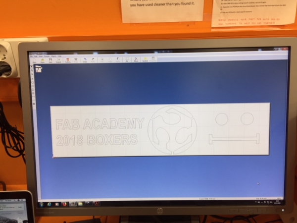
This is how the CutStudio looks like. I imported my bpm. images from Inkscape simply by copy-pasting them one by
one to CutStudio.
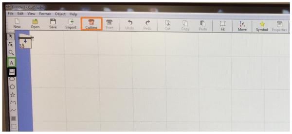
I mainly used following functions in CutStudio to preapare my design:
- To cut I used "Cutting" (Orange box)
- To create word art I used A-icon (Green box)
- To create frame around my designs, I used rectangle-icon (Black box)
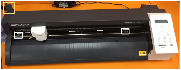
Before going to deep in preparing the cutting file, I had to prepare the vinyl cutter. First, I put the vinyl which I wanted
to use (white) inside the machine and locked it with a leveler. Then I put manually machine´s measuring rolls on the correct
width which resembled the width of which I wanted to use for printing. (White boxes: measuring rolls, Yellow box: lever)
Next I used the machine interface to power the machine. Macine interface can be found from the right side of the vinyl cutter
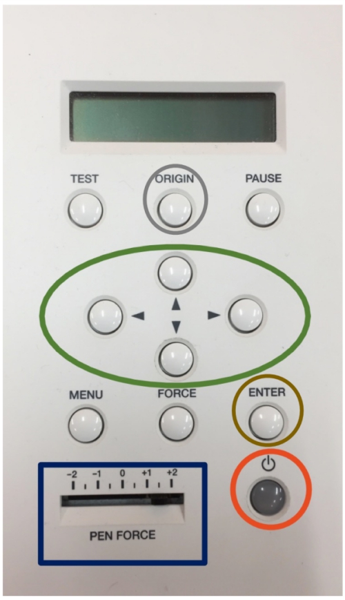
I mainly used following functions with the cutter:
- Direction buttons to choose origin (Green ellipse)
- Pen Force slider to change the cutting depth (Blue box)
- Power button to power the machine (Red ellipse)
- Origin button to define origin (Grey ellipse)
- Enter button to accept (Brown ellipse)
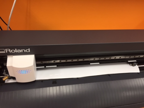
When the machine was powered on, I selected SELECT PIECE and EDGE command on the screen and pressed Enter button. By this, the
machine acts now on like it is cutting a sheet of vinyl and start the cutting from the lowest left point of the vinyl it
founds. After a while, the machine scanned the sheet and went to the bottom left corner to start the cutting.
Next, it was time to initiate the cutting procedure by sending the file from the CutStudio to the machine.
Antti gave me tips to size my designs correctly. From the boxers, I measured, that my Fabacademy text should be around 18cm long.
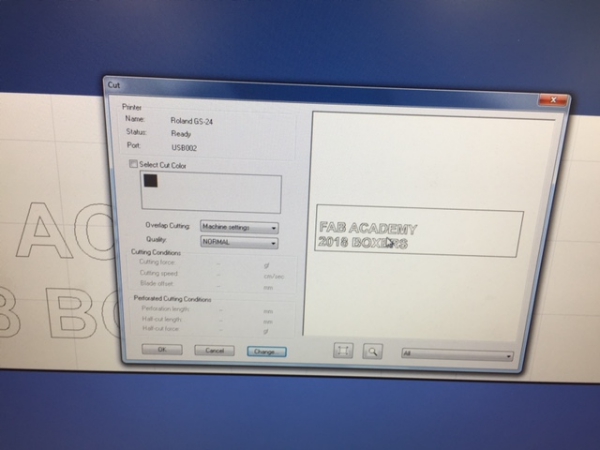
To see how much material I could use, I used following procedure in CutStudio:
1. Click "Cutting"
2. Click "Change" in opened window
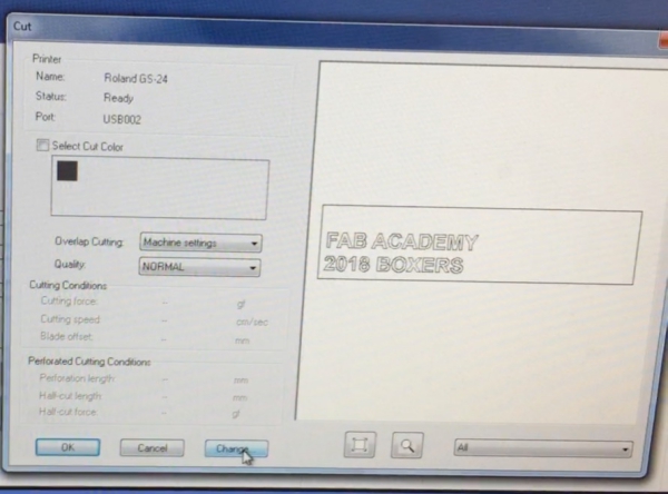
3. Click "Change" in opened window
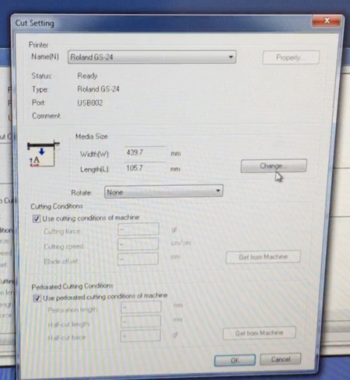
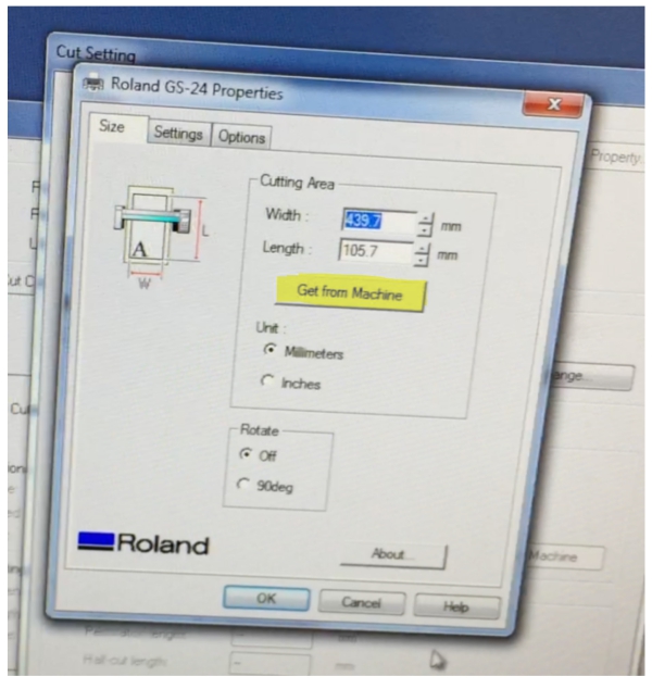
4. Click "Get from Machine" and click "Ok" to change the size of the design surface to correspond the size of the vinyl sheet
5. Verify the change by checking the change from the bottom right corner
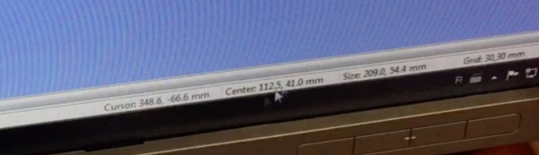
When this was done, I added and resized my other designs to fit to this sheet
Then I initialized thecutting procedure by clickin "Cutting", clicking "Ok" and by clicking Enter button on machine interface.
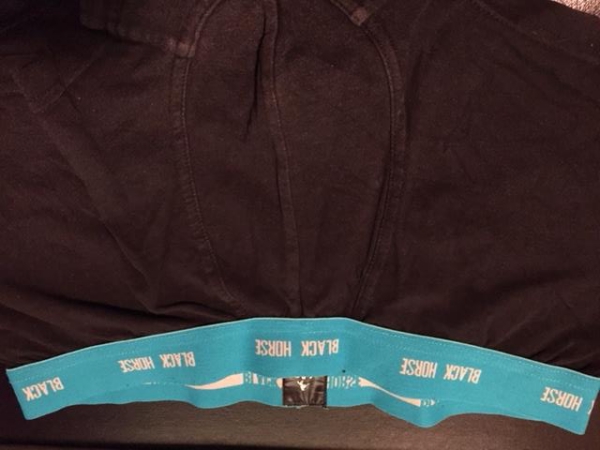
The machine started to print and the printing was success! However...
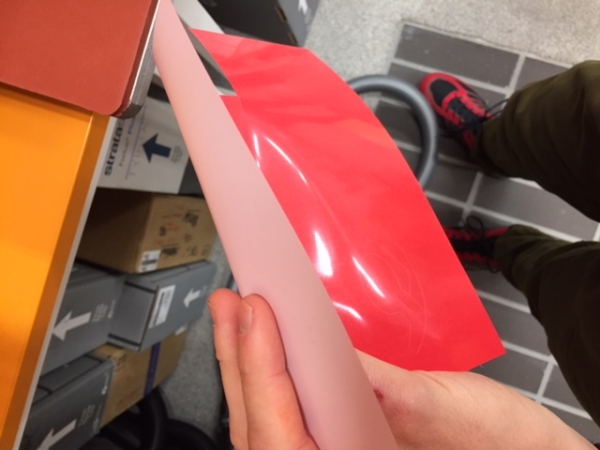
Oops, wrong material ._.
Unfortunately, I had accidentally used sticker vinyl material instead of rubber material which was designed for clothes.
Therefore, as an end result, I got stickers, not design that could be ironed to the boxers. This is what I should have used:
I didn´t let this to be my end. I decided to use these stickers and choose following items to be tagged with the stickers:
- Notebook
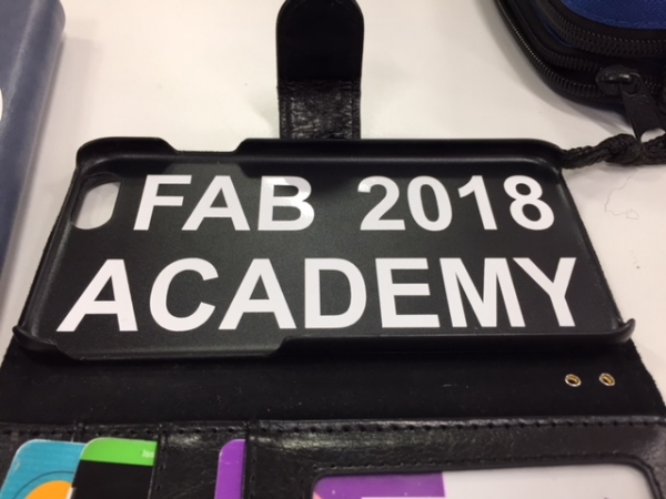
- Phone case
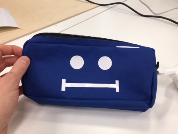
- Pencil case
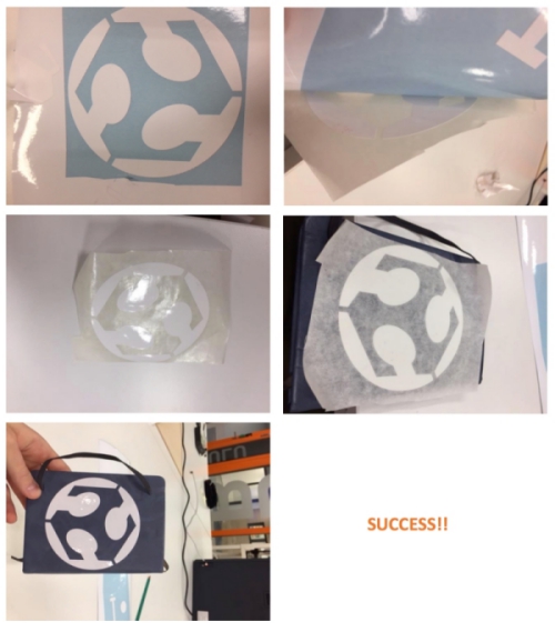
First, I removed unnecessary sticker surface and then I tore my designs one by one of from the vinyl sticker sheet with a
help of sticky transfer sheet. Finally, I tagged the items with the stickers.
Here is the process for the notebook:
Here are the other items after the modification.
Pencil case:
Phone case:
And after that, this week´s assigments were ready!
FILES made THIS WEEK

This work is licensed under a Creative Commons Attribution 4.0 International License.