Assignment 6
7.2.2018
Topic: 3D scanning and printing
Goals of this week:
- Design and 3D print an object (small, few cm) that could not be made
subtractively (Individual)
- 3D scan an object (and optionally print it) (Individual)
- test the design rules for your 3D printer(s)(Group) (LINK)
Deciding what to print
First task for this week was to print something with 3d printer which would be otherwise imposible or very hard to do.
I got an idea from one of my fellow student´s to create diamond necklace jewerly piece with some kind of rock inside.
Therefore, I decided to create a diamond shaped shell...:
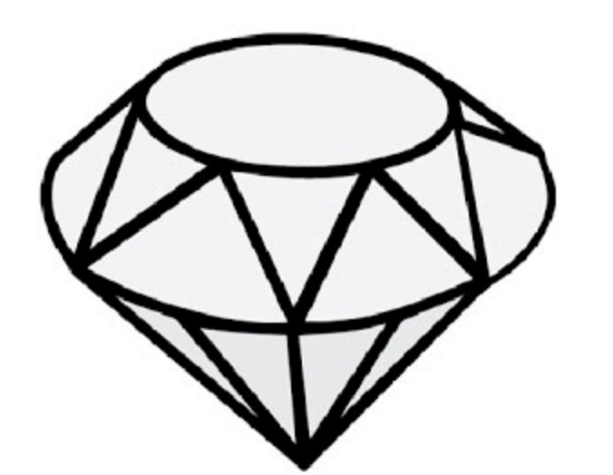
... and put a ball inside which would be connected to jewerly ring outside of the
diamond. The ball would be sized so that it could´t be taken out from the diamond
shell.
This design can´t be made subtractively because the ball is inside the hollow diamond, so subtractively process would break
the diamond on the top.
Creating and printing the diamond
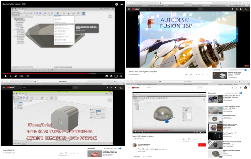
I used following tutorials to help me to model the diamond in Fusion 360. (First, Second, Third and Fourth)
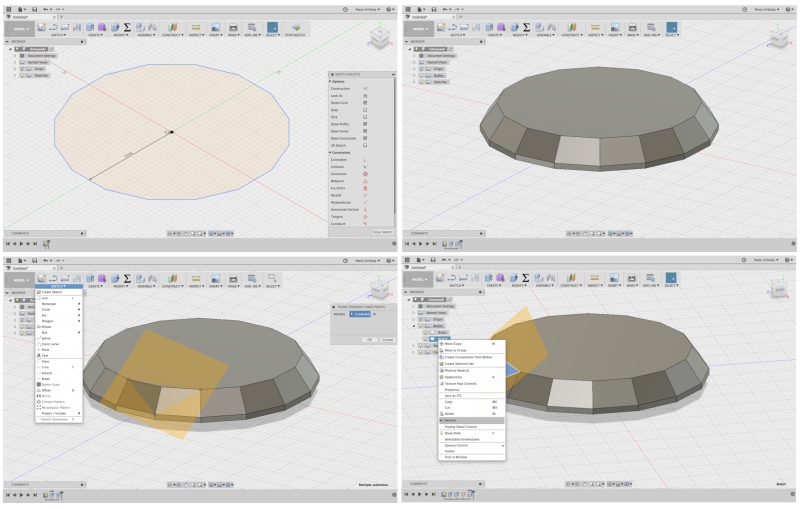
Through trial and error, modelling process went forward as follow:
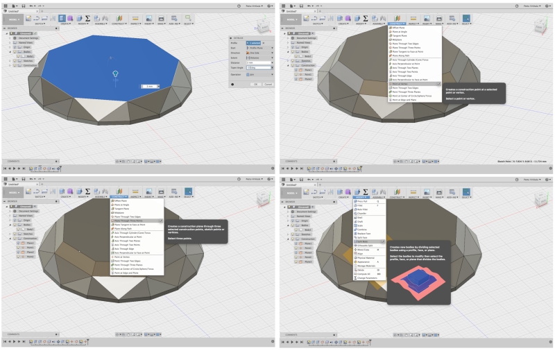
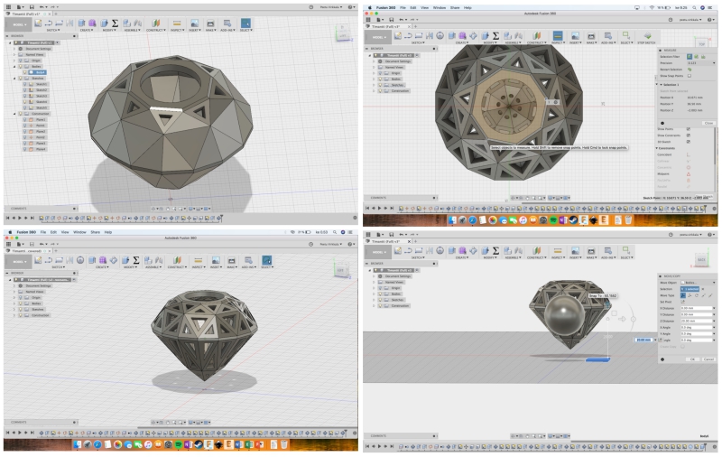
1. (Top left): Created 16 side polygon
2. (Top right): Extruded once few mm. and then extruded again with -35 degree angle
3. (Bottom left): Created new sketching surface
4. (Bottom right): Splited the body to two bodies
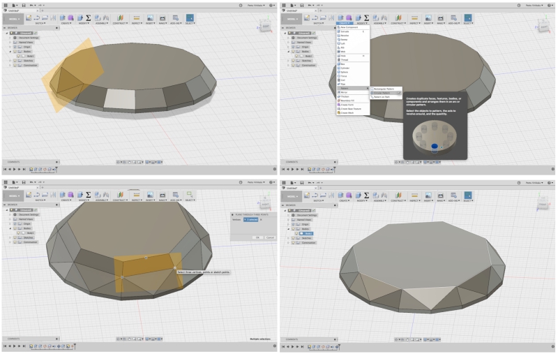
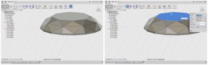
5. (Top left): Deleted splited body
6. (Top right): Used circular pattern to copy the change 360 degree around the model
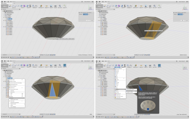
7. (Bottom left): Extruded with -40 degree angle and created new sketcing surface by using 3 points from the design.
These poinst are: Bottom ends and top midpoint of one of the extrude shapes.
8. (Bottom right): As before, the body is split, splitted body is deleted, and circular pattern is used to copy the change 360 degree
around the model
9. (Top left): Extruded again with -35 degree
10. (Top right): Identifying points for the new sketching surface
11. (Bottom left): Identifying points for the new sketching surface continues
12. (Bottom right): The body is split again
13. (Left): Circular pattern is used to copy the change 360 degree
14. (Right): Small extrude is made with -60 degree angle
15. (Top left): -50 degree angle is made down
16. (Top right): New sketcing surface is created
17. (Bottom left): The body is split by using this nnew sketching surface
18. (Bottom right): Circular pattern is used to copy the change 360 degree
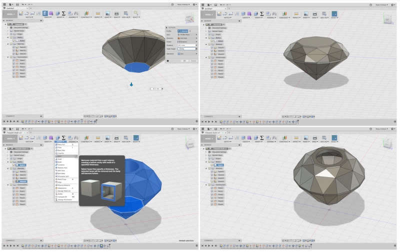
19. (Top left): -50 degree angle is finished
20. (Top right): Basic diamond is ready! Now is time to create shell out of it!
21. (Bottom left): I used shell tool to create a shell with material depth of 2 mm
22. (Bottom right): Created a hole for the jewerly ring
23. (Top left) Created triangular hole to one of the sides of diamond. Used circular pattern to copy it around 360 degree
24. (Top right): Repeated the same procedure for every side of the diamond. Principle was to leave at least 1mm material between the
holes and the walls
25. (Bottom left): Checking the end result. Diamond is now ready!
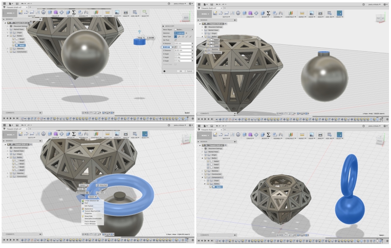
26. (Bottom right): Sphere is created to be put inside the diamond
27. (Top left) Handle piece is created
28. (Top right): Handle piece is attached to the sphere
29. (Bottom left): Handle ring is created
30. (Bottom right): Handle ring is attached to the sphere
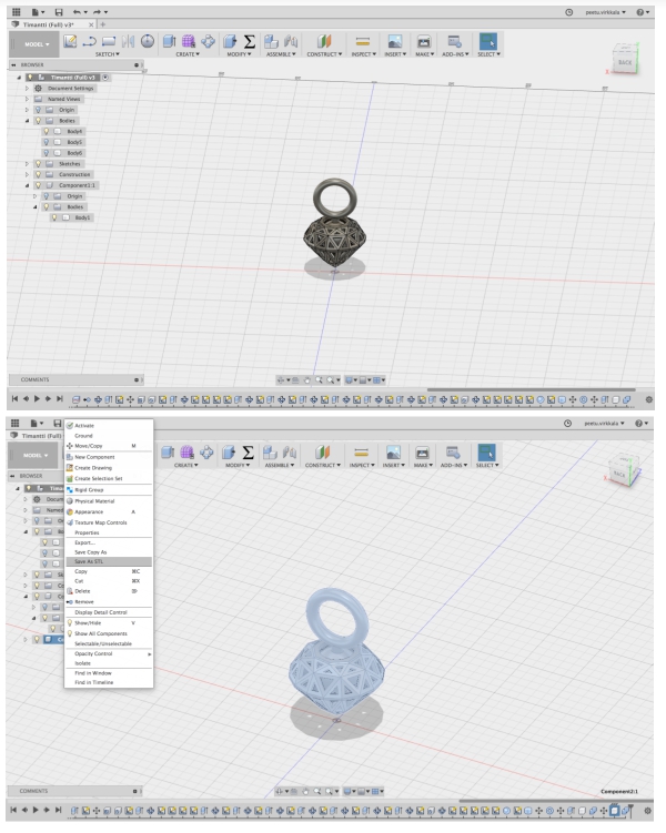
31. (Top): Sphere is put inside of the diamond so that it isn´t touching diamond´s walls
32. (Bottom): The design is ready! The design is saved as a STL. file to my computer
When the STL file was ready, I exported it to Fortus 380mc software and prepared it for printing. My print was added to other people´s
printings. Printing procedure with Fortus went forward as follow:
1. Open Strasys printing software on connected computer and import the STL. file
2. Choose prefered interior style, I chosed double sparce
3. Press green flag symbol to make each layer and supports visible
4. Press tool path and press build to open printing window
5. Place your model as you want in this window and press Build
6. Prepare the printer (already done by others)
7. Choose the sent file which was build in the software and press Go button to intialize the printing procedure
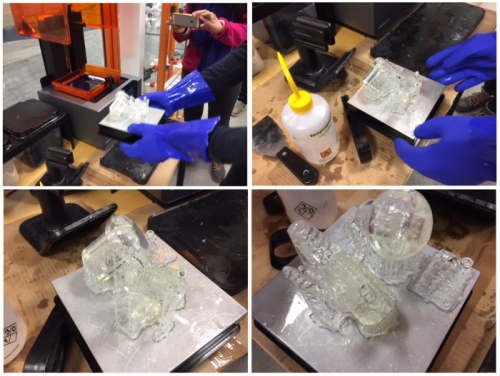
The printing took around 3.5 hours. When it was ready, I took my designs out and removed them from the sheet:
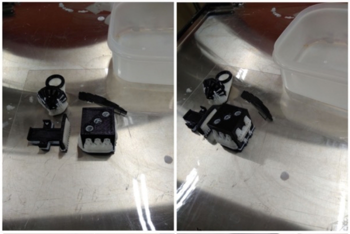
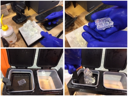
Next, I put my printed piece inside of caustic soda container to melt white structure material away. After a few hours,
I took my piece out from the container and cleaned it with water. Then my 3D design was ready!:
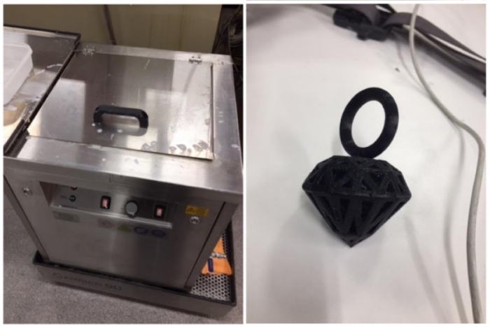
My design was little lose and the jewel ring was little too big but otherwise the
designed turned out nicely. I´m planning to edit this design during the future weeks
by adding a led inside the diamond, (probably during input and output weeks).
Next, it was time to do photogramethry.
Photogramethry
For the scanning assigment, I wanted to use photogramethry. Last summer, I attended to UBISS
where there was workshop about virtual cities and photogramethry where students modelled
Oulu marketplace area. I was impressed about this technology and wanted to try it also by myself.
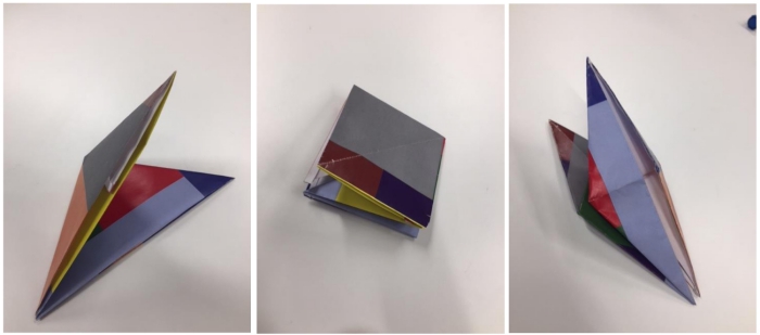
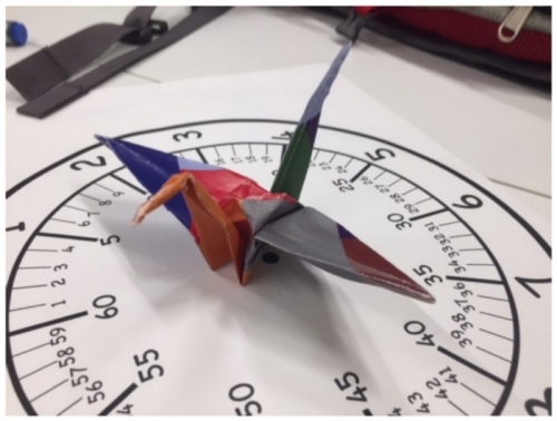
I used my Iphone 6 and Autodeck software Recap Pro to do the photogramethry. First, I modeled origami crane by using colorfull
paper which I then folded to the shape of origami crane:
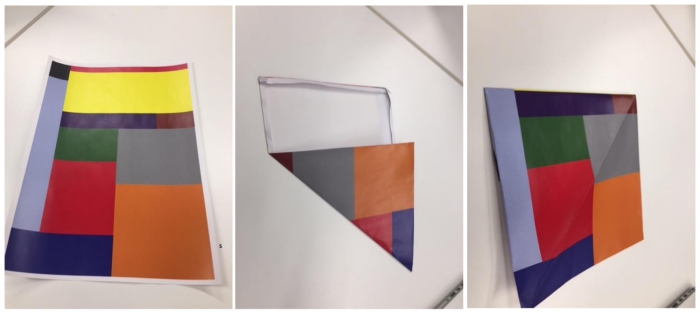
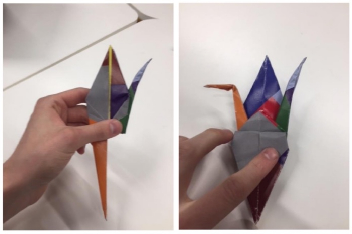
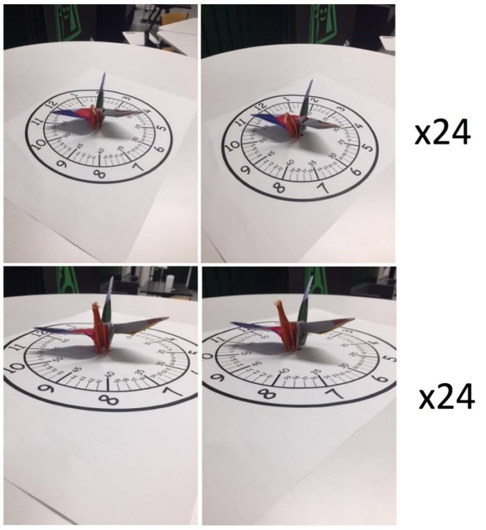
Then I put the crane to the top of the paper with clock-face design...
...and took 48 pictures 360 degree around the model from different heights and widths:
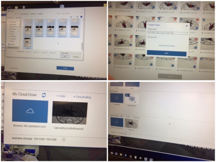
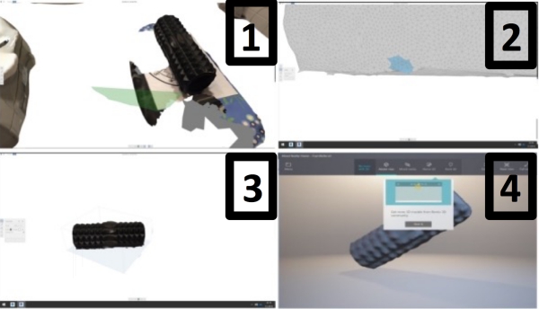
When I had took the images, I sended them to my e-mail, saved them to my computer and used them as reference images in Recap
Pro. Then I sended my images to Autodeck server and waited until the model was ready.
Left top: chosing the images from the computer, Right top: naming the project, Left bottom: Autodeck cloud creates 3D file from the
image set, Right bottom: 3D file is ready to be opened
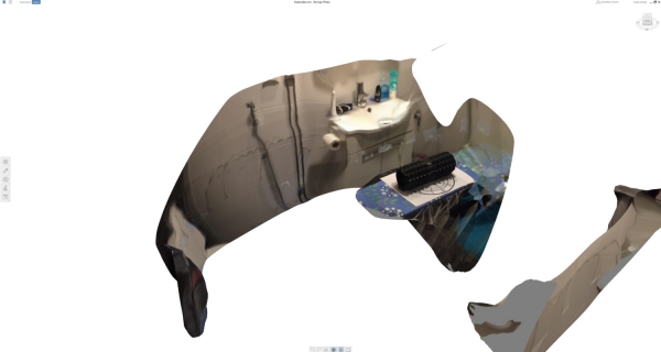
The end result wasn´t what I expected:
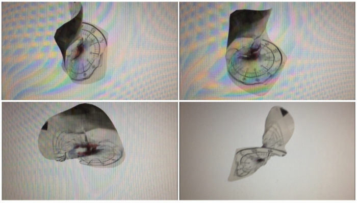
The modeling process failed probably due to my images. From the model, it can be seen that my image taking position from some side
of the model were lacking. This made it hard for the program to understand the pictures and to form the model.
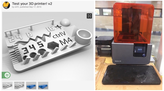
However, I tried again at home by taking pictures of my foam roller in my bathroom. After the same steps as before, I managed to get
a reasonable model:
I was happy with the modelling result and prepared the model to be downloaded as a STL. file with following process:
1: Eliminate extra material around the model
- Select unnecessary parts in the model and delete them (Edit> Delete)
2: Fill the holes in the model
- Select analysis (Analysis> Diagnostics) to locate holes and click Fix to fix them
3. Resize the model
- Select "Scale and Units" and change the scale
4. Export and investigate the model:
- Select "Export model" and save it as a stl. file. Investigate it with a software able to view stl. files
In future, I can use this STL file to create small foamroller around stick to be used as a leg message device
Summary: Advantages and disadvantages of 3d printing and scanning
According to my experience, 3d printing has following advantages and disadvantages:
+ Possible to make parts that would be hard or imposible to do subractively
+ Amount of detail
+ Simple to design
- Printing and dissolving takes time
- Material limitations
- Printing limitations
Respectively, 3d scanning has following advantages and disadvantages:
+ Scan complicated models
+ Models are easy to handle
+ Can be done easily for example with a cellphone
- Doesn´t work always: errors are hard to identify
- Scanning detail limits
- Scanning area limits
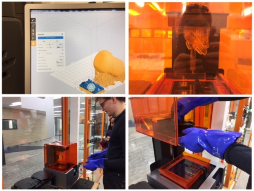
EXTRA: Group work - Test the design rules for your 3D printer(s) (LINK)
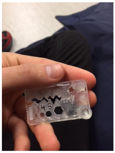
As a part of this week´s group assigment, I printed 3D printer test
piece (Link) by using formlabs machine:
I used folloving settings for the print and sended the print for the
machine and started the printing. When the printer was ready, I took
my model and other people´s model out.
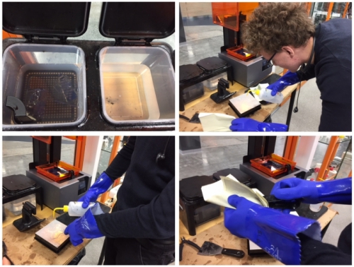
Prints are taken out from the machine:
Prints are detached and put into dirty liquid:
We wait 10 minutes by cleaning dirty surfaces with alcohol:
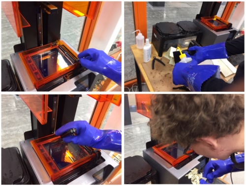
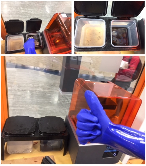
After 10 minutes, prints are put into clean liquid:
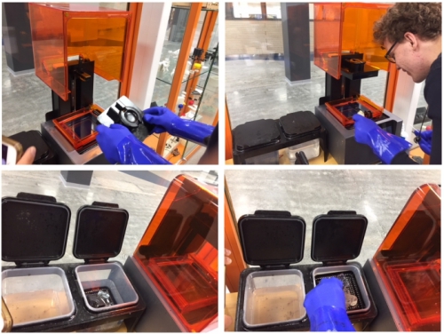
We wait 10 minutes and take prints out from clean liquid. we are ready to
process the prints further!:
I tidy up my test piece, washed it, and got following end result:
FILES made THIS WEEK

This work is licensed under a Creative Commons Attribution 4.0 International License.