Assignment 9
14.3.2018
Topic: Emedded programming
Goals of this week:
- Read a microcontroller data sheet (individual)
- Program your board to do something with as many different programming
languages and programming environments as possible (individual)
- Compare the performance and development workflows for other architectures
(Group) (LINK)
Getting there to start
Juha-Pekka gave us a lecture about how to do embedded programming
by using Atmel studio.
My laptop is running macOS and Atnel studio can´t be run on it, so I tried to use Atmel
studio on Fablab Oulu´s Desktop computer. I used it as follow:
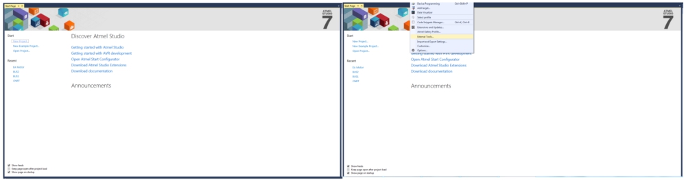
1. Install and open Atmel (Left). Open "External tools" (Right).
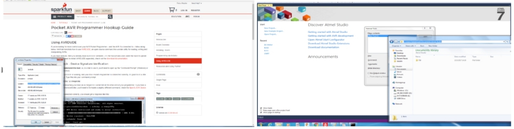
2. Make sure that avrdude is installed (Left), and refer to it as "Initial Directory" (Right).
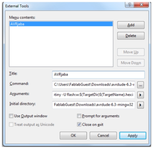
3. Fill arguments with necessary information and click "Ok"
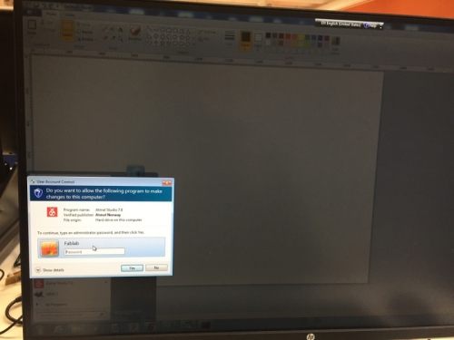
Unfortunatelly, I wasn´t able to go forward with Atmel studio after this, because I would
have needed admistrator rights:
Hence, I decided to leave Atmel studio behind and do same things on corresponding macOS software
and/or solution
However before going to this process, I found out that to do this week´s individual board programming task,
I had to first program my programmer and redrawn echo-hello-world board to be able to program it to
do new things. I had not had time to do this during the previously weeks, so I had to do it now before going
deep to this week´s core assigment.
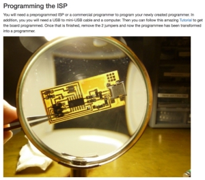
Programming the programmer
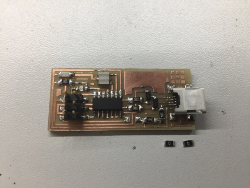
I started by programming my programmer from week5. First I visited Ali´s site to understand
how to prepare and program the board. I found out that I had to cut 2 jumper resistors from the
programmer when programming was ready and follow spesific tutorial to program the programmer
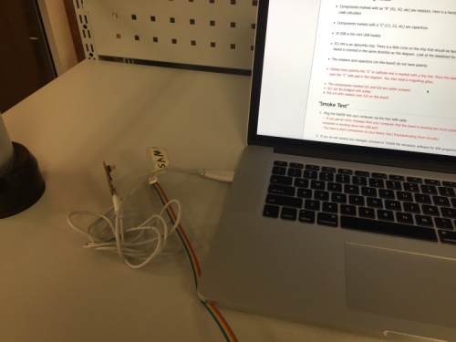
First, I made smoke test to be comfortable with inserting the programmer to my computer:
Next I programed my board by following this tutorial
- Installed CrossPack for AVR
- Installed Xcode
- Downloaded programming firmware
I edited the firmware code by editing line:"AVRDUDE = avrdude -c avrisp2 -P usb -p $(DEVICE)" to be "AVRDUDE
= avrdude -c usbtiny -p $(DEVICE)". This change can be seen in the image below (line 16 = before editing,
line 15= after editing):

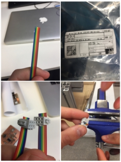
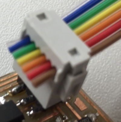
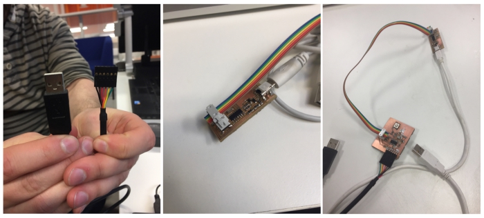
Before going any further, I also prepared ribbon cord to be able to connect the programmer to the board
Then I proceed with the programmer installation by connecting the programmer to my computer with a mini-USB cable
and by connecting programmed usbtiny programmer made by Antti to my computer with a mini-USB cable. Then I connected
Antti´s programmer
to my programmer with a 3x2 cable to 3x2 headers:
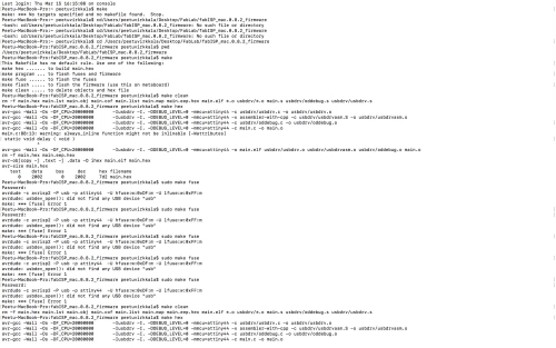
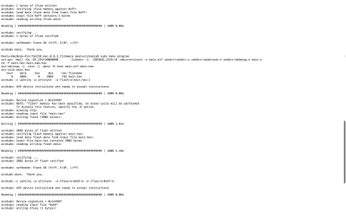
Then I opened Terminal, travelled to folder where I was storing the progamming firware, and used following commands:
- make clean
- make hex
- sudo make fuse
- sudo make program
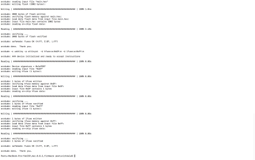
I got same results as in the tutorial. The programmer should be now programmed correctly:
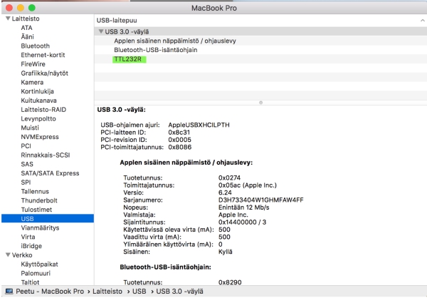
Finally, I removed 2 jumpers mentioned above and tested if my computer found the programmer:
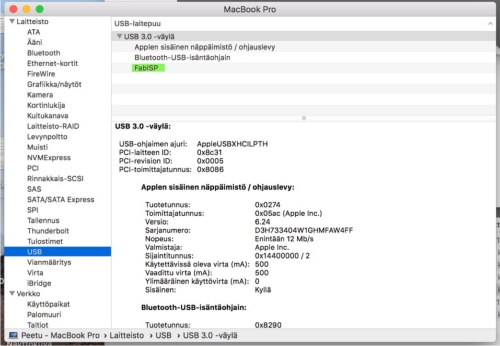
My programmer was now ready!
Programming the board
Programming the board was more complicated task than programming the programmer. I approached
this challenge by following my Fablab Oulu fellow Megumi´s instructions and this useful Tutorial for macOS.
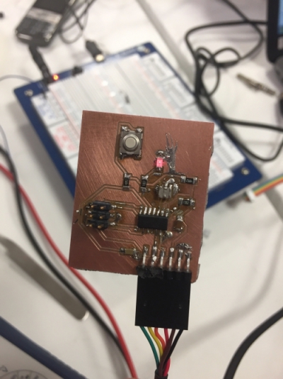
First, I connected the board with the programmer by using the ribon cable and pin connector cable:
Next, I connected both the board and the programmer to the computer usb ports:
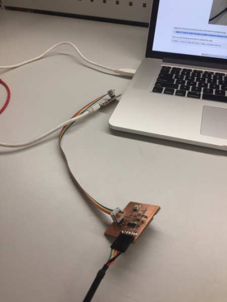
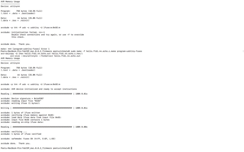
Then, I continued with following commands as mentioned in tutorial for mmacOS:
However, when I tried to create fuses. I got constantly following error:
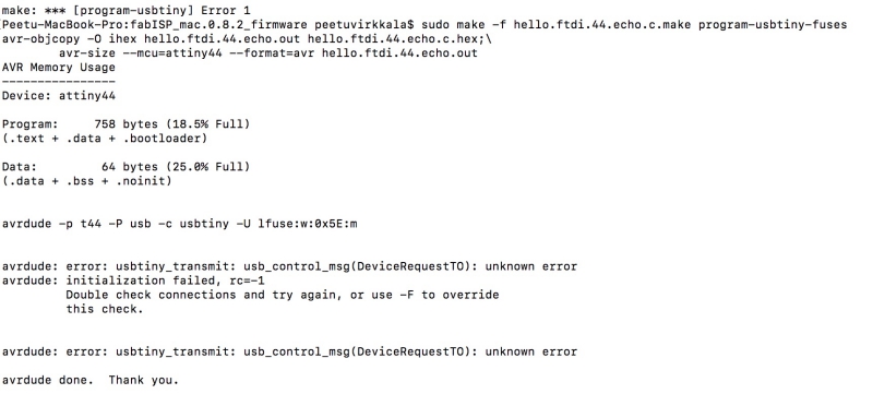
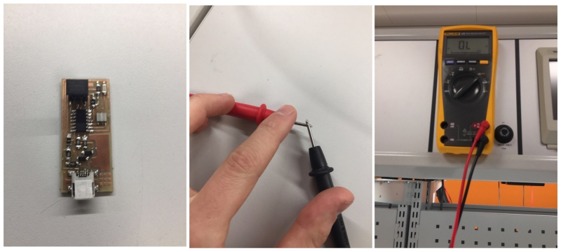
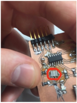
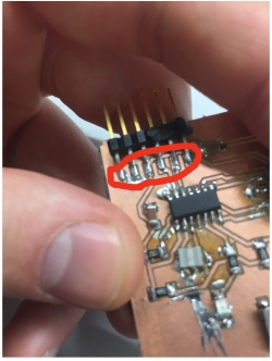
After a while, I managed to verify that the problem was due to the soldering problem in my board.
I used multimeter to verify the location of the problem and found shock problem from my resonator:
To solve this, I took the resonator of from my board and soldered new resonator on its place. After
this, I could see my board as an usb device on my computer:
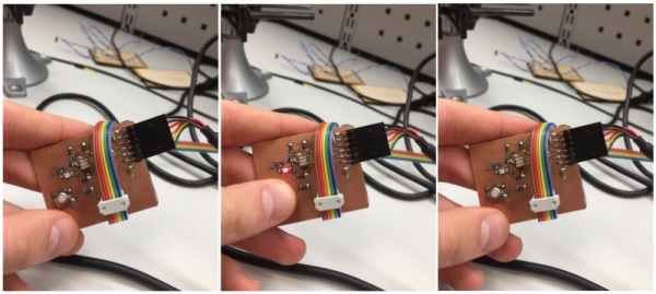
Then, the code run perfectly:
Led was now working!
However, the board was still working wrong way. According to Hello World file, led shouldn´t work
when the board is connected to the power source. After analyzing my soldering little bit more. I
identified a problem in pins: By pushing them against the board surface, I could get led to go dark.
Therefore. I soldered those pins better:
Now the led was flashing only occasionally. In future, I should remove some solder between the left
most pins to eliminate this occasionally led flashing.
Despite this, I managed to get my board to run the program now:
My board was now ready to be programmed!
Learning more about the microcontroller data sheet
One part of this week´s tasks was to learn more about the ATTiny microcontrollers by reading ATTiny
microcontroller data sheet.
Most of the text was too complicated for me due to my lack of the knowledge of the topic, but I managed
to summarize from the many different topic..
...that these are the keypoints that the datasheet points out:
- Architecture overview
- ALU, memories, clock system
- Different modes of operations (sleep mode etc.)
- Resets and interrupts
- IO ports and operations
- Programming + programming examples
- Electrical characteristics
- Performance characteristics
- Summary of the instructions set
Later on, if I need more information about some of these topics, I know now where to find the information.
Programming my board with Megumi´s code
I was late for this week´s assigment so I decided to follow Mequmi´s process and do my own changes for the code because
she was also programming on macOS.
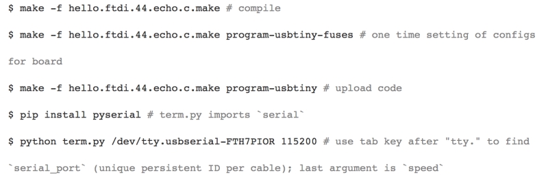
When I read her documentation, I finally understood how the installation process goes on with ATTiny44:
1. Compile code-file so that ATTiny understands commands (make -f "".make)
2. Set configuration of the board for programming (make -f "" program-usbtiny-fuses)
3. Upload the code (make -f "" program-usbtiny)
4. If needed, open python serial monitor (python term.py /dev/tty"" 115200)
I started by downloading one of her code´s to my computer and installed it to my board.

Installing went well but my board was not working like Megumi´s board with the same code. My led was blinking constantly
whereas Megumi´s led was blinking only after pushing the button. To solve this, I look through the code.
It seemed like that Megumi used ATTiny ports different way than me. To see the differences, I opened my design in Eagle.
In Megumi´s code, the button was put to port A pin 3, whereas in my desing, the pin for the button was put to port A pin 7.
Port B pin 2 connected to LED was same for my design as in her design (Blue route).
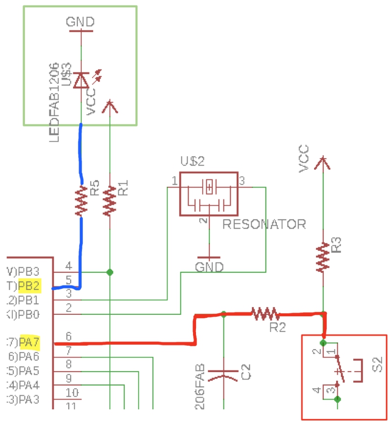
Therefore, I changed PA3 to PA7 in the code:
Then I did installation process again. My board´s led was now flashing so the program had succesfully changed. However
The board was not functioning like Megumi had mentioned, led was flashing without clicking the button and clicking the
button didn´t do anything.
I tried another of Megumi´s files but decided to try to make make. file by myself because I didn´t know how to
do it from scratch. Therefore, I downloaded only the following file from Megumi´s webpage:
Then I opened previous make. files and found out that the make files are otherwise exactly same, but they have
different project names. Therefore, I created make. file for blink_button1 by changing the project name of the previous
make file.
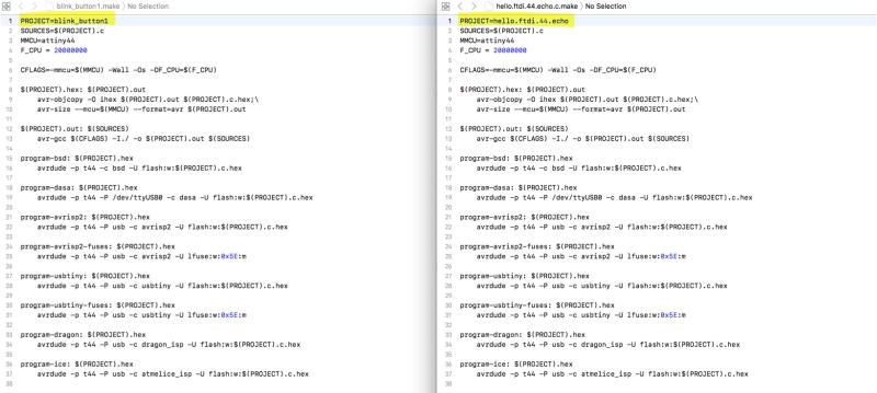
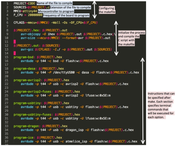
Structure of the make file can be seen below:
Next I went forward as before and downloaded blink_button1 software to my board. Problem was still occuring, but the led
was now flashing constantly. This eliminated my problem to two possible causes:
1. The button was soldered wrong way or it was not working
2. My code was not working as it should be working
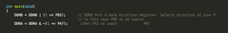
Before touching my solderings, I decided to check the code and I found the problem. I was still refering to the port PA3 for
the button instead of PA7 in one part of the code. Therefore I changed it.
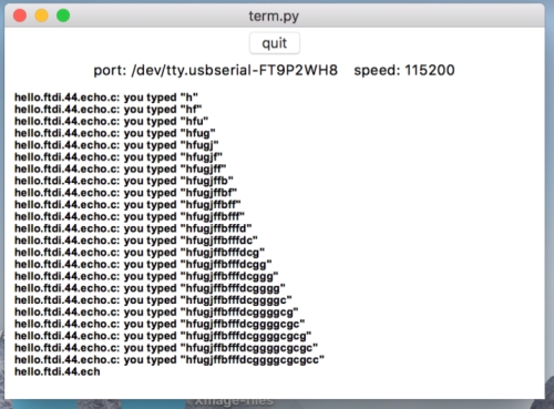
Then I sent the program again and Vola! The board worked as it was meant to be worked. When button was pressed, led was flashing:
Now, I was ready to create my own code for the board!
Programming my board to do something
I decided to create code by editing Megumi´s code that:
- Flash the led few seconds constantly when the button is pressed
I started by oppening blink_button1.c and added //Modified by Peetu Virkkala on 6.04.2018. Then I began to play with the code
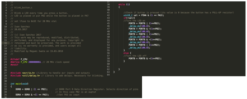
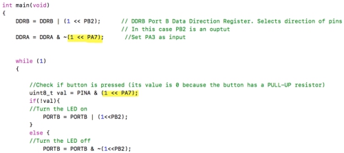
I didn´t have previous experience about C-code but I with simple logic I found out that the following lines controlled the blinking process:
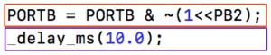
First line (red box) defines the pin (in portB) which is in my case led´s pin that is then activated. The second line (purple box) defines the
delay which the pin waits before it activates.
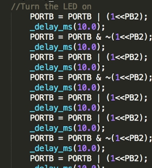
To accomplish my blinking goal, I copied these lines 30 times to get the code where the button press makes the LED to flash for 3 seconds
30 times. Each of these 30 lines turns the LED on for 10ms so in total led will flash 30 times in 3 seconds. Part of this structure can be seen below:
Finally I ensured that I was using right frequency in my code. My board has 20 MHz external clock (resonator) which I´m using so I
addressed this in my code by adding "#define F_CPU 20000000L" to the beginning part of my code:

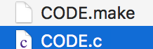
Then my code was ready. I saved it as CODE.c and made make file with similar name.
Finally, I proceeded with the programing process as previously and the code was sent to the board. Board was working as it should be working.
My embedded programming week was now ready!
EXTRA: OH NO!
So this happened this week:
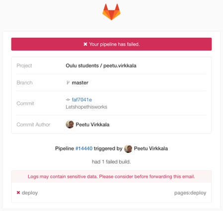
And when I went to gitLAB i found this error from the pipeline view:
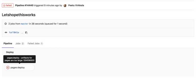
It took me some time to understand what was the problem. First I realized that I had used too much
space at gitLAB. I started to wonder how: I thought that my images had been sized right way, my files
were mostly small and I hadn´t got any feedback from my instructors. However, I realized I was partly
wrong when I found this:
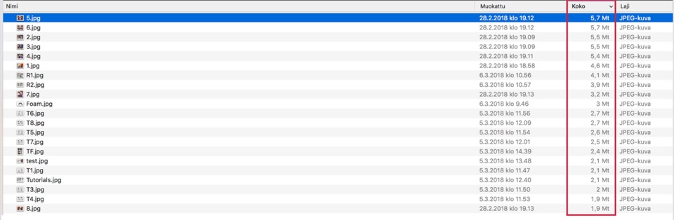
So the reason for the problem was really my picture sizes. I had thought that my pictures were small
and didn´t use that much space when I had edited them through onenote and screen captures, but because my
computer screen´s resolution is 2880 x 1800, those screnshots were very big.
To solve this problem, I downloaded PhotoScape X to edit the pictures more efficiently and right way:

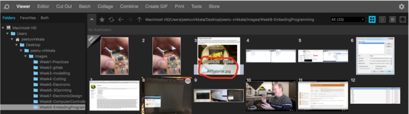
With the PhotoScape X, I managed to make my repository 70% smaller than before. I will be continuing to
use it so this kind of problem shouldn´t occur anymore.
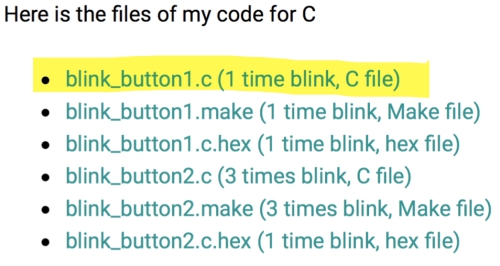
FILES made THIS WEEK

This work is licensed under a Creative Commons Attribution 4.0 International License.