FINAL PROJECT
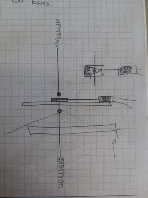
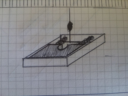
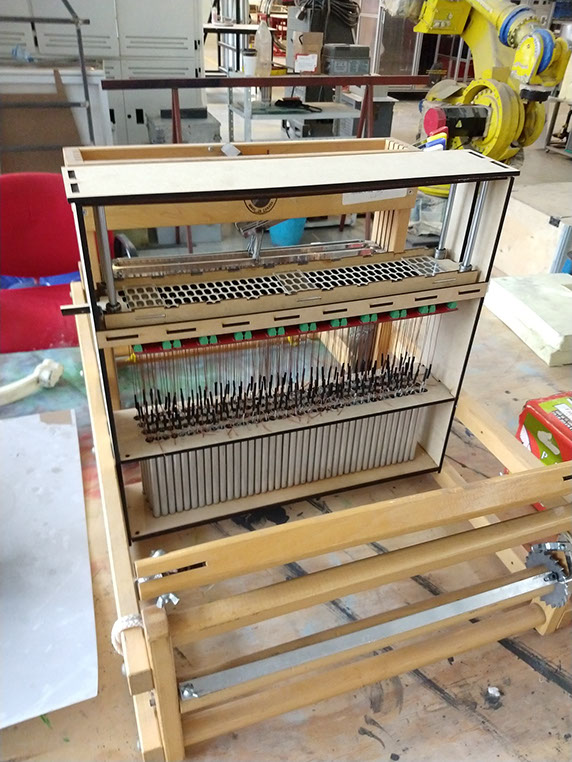
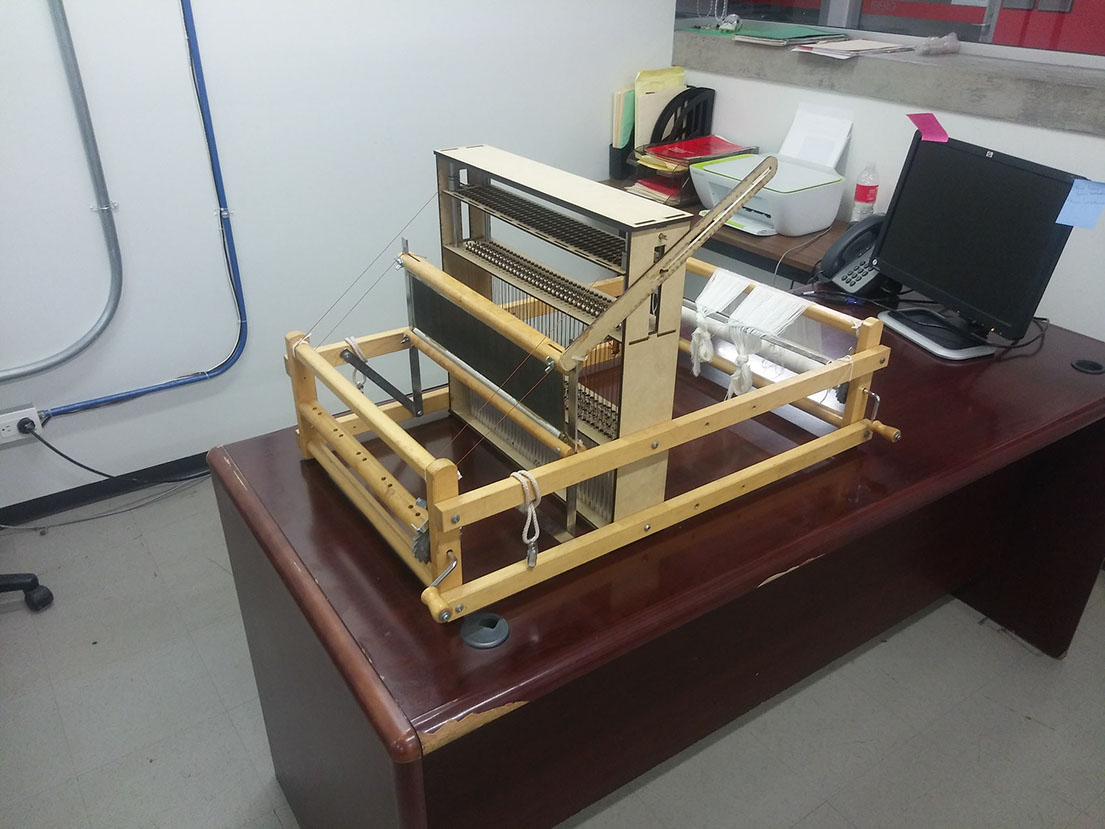
Here's a sketch of how my final project may look like.
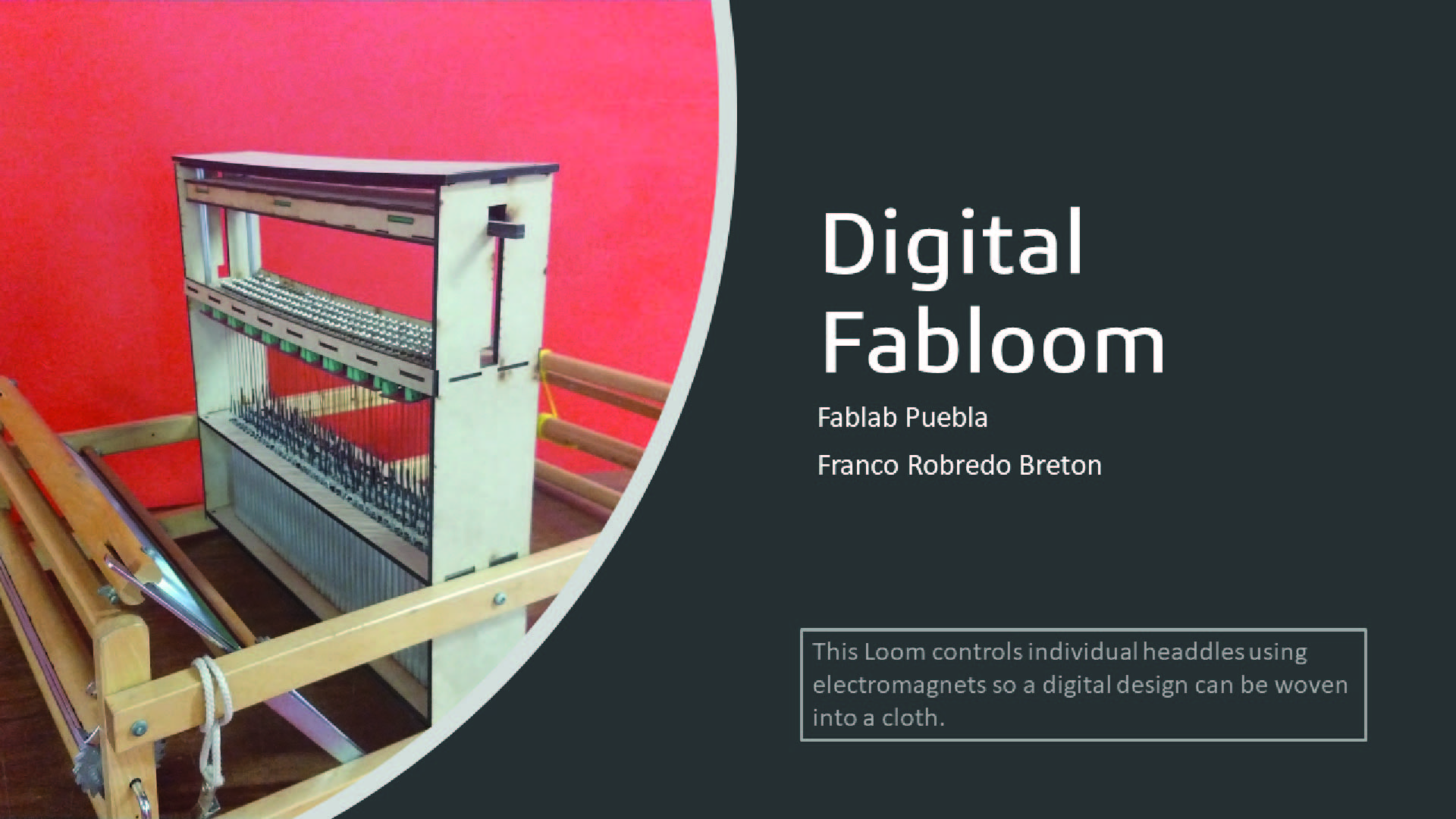
It is a jacquard based digital loom. The computer transforms a pixelated image into binary code, the code is sent to a microcontroller that controls electromagnets, wich then make the strings go up or down forming the shed.
Background:
This project was based on a couple of other comercial looms and a previous Fab Academy project http://archive.fabacademy.org/archives/2016/fablabpuebla/students/261/final-project.html made by Octavio Muñoz.
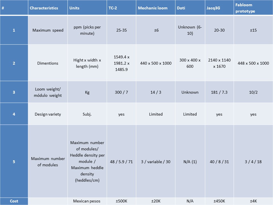
I made a reaserch for other personal digital looms in the market, I made a data table of the most important information including picks per minute, dimentions, weight and number of interchangable modules.
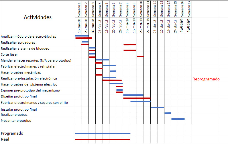
I made a little plan of action so I could have some order and made the most of my time.
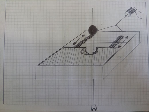
The first problem I faced was to find a way to control each headdle's movement with as little imput as possible, this were the first ideas that came to my mind, I needed to trap a little ball so the down movement would block and the warp yarn would keep up and let the filling yarn through the space between upper and lower yarns.
The idea was good, but I needed a lot of force to move those springs, so I came up with another idea, instead of moving something to trap the ball I could simply divert the ball to a place where it would be trapped.
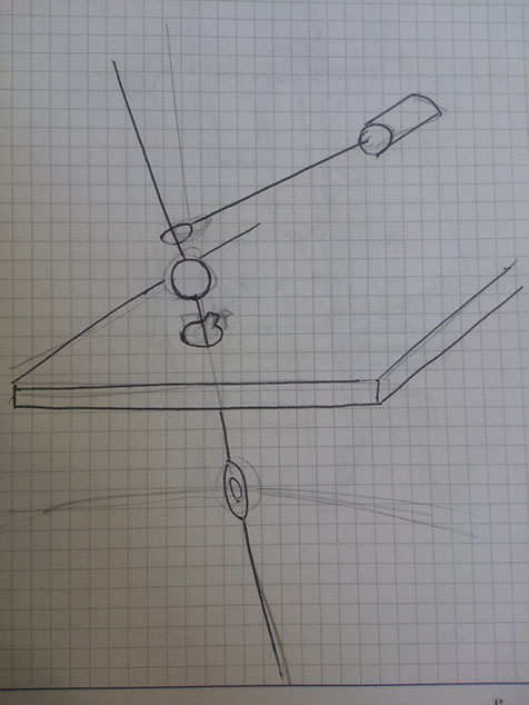
And for making the movement I needed something that could be controled by a computer, wich means an electromechanic device, so a linear actuator was the obvious answer.
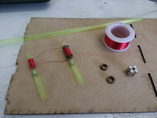
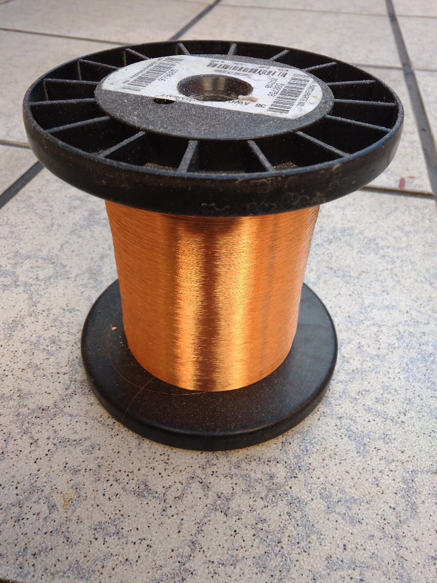
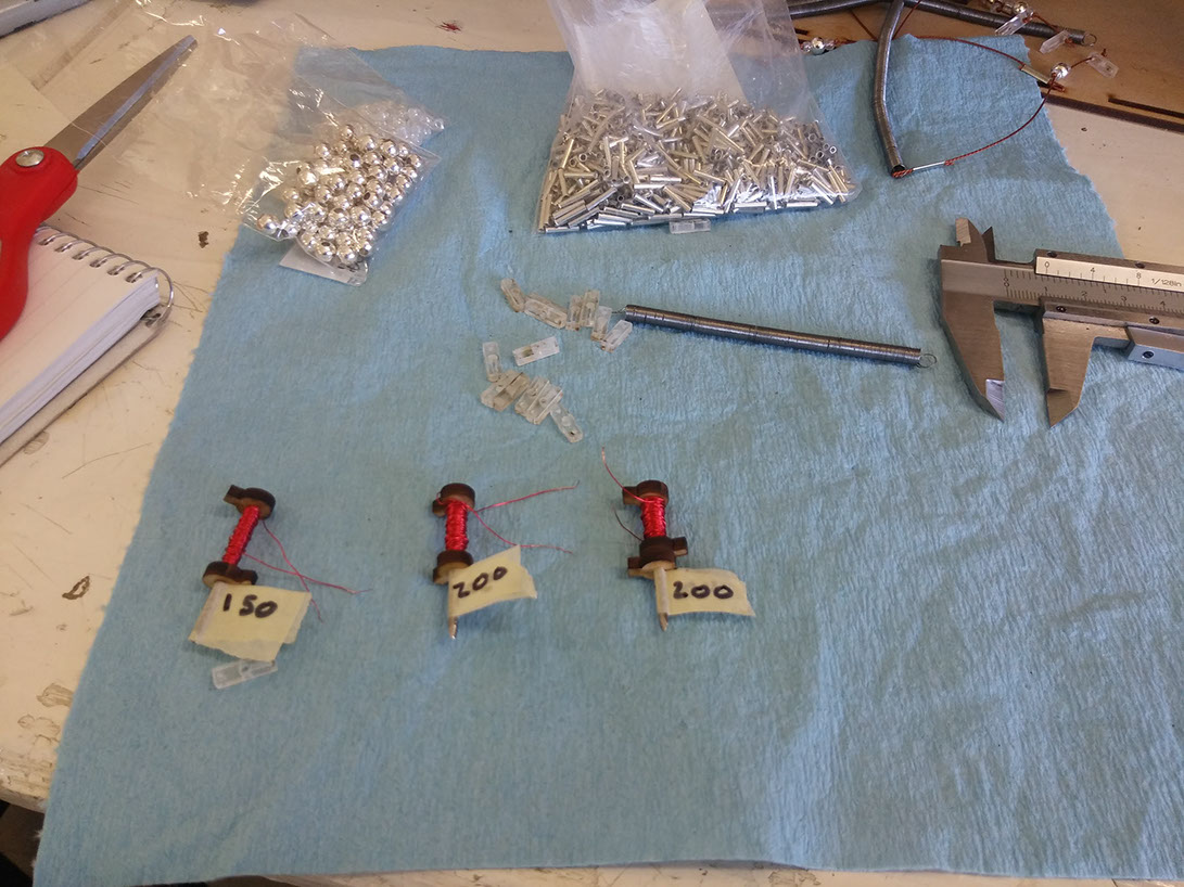
Another problem I faced was the making of this actuators, I needed to calculate the force needed to divert the ball, I got to the ecuation of magnetic field=((material permeability)(number of turns)(current flow))/length of the solenoid. Now, the current flow couldn't be over the current permited in the wire, if it were then the wire would melt. The correct wire to use was a AWG 36 magnetic wire.
The first coils where made by hand and counting the turns, I used an internal neodimium magnet to act with the magnetic field produced by the coil outside, the magnet moved a piece of thin wire atached to the string that acts as the headdle with a ball that is suposed to lock the position of the headdle.
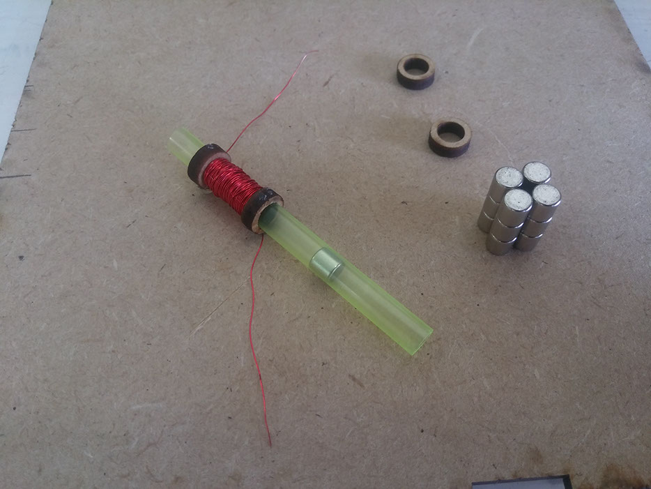
As you can see in the image below this actuator takes a lot of space and is prone to get stuck and fail, also this mechanism uses two springs for each headdle, wich is really really expensive when you try to make as much headdles as possible.
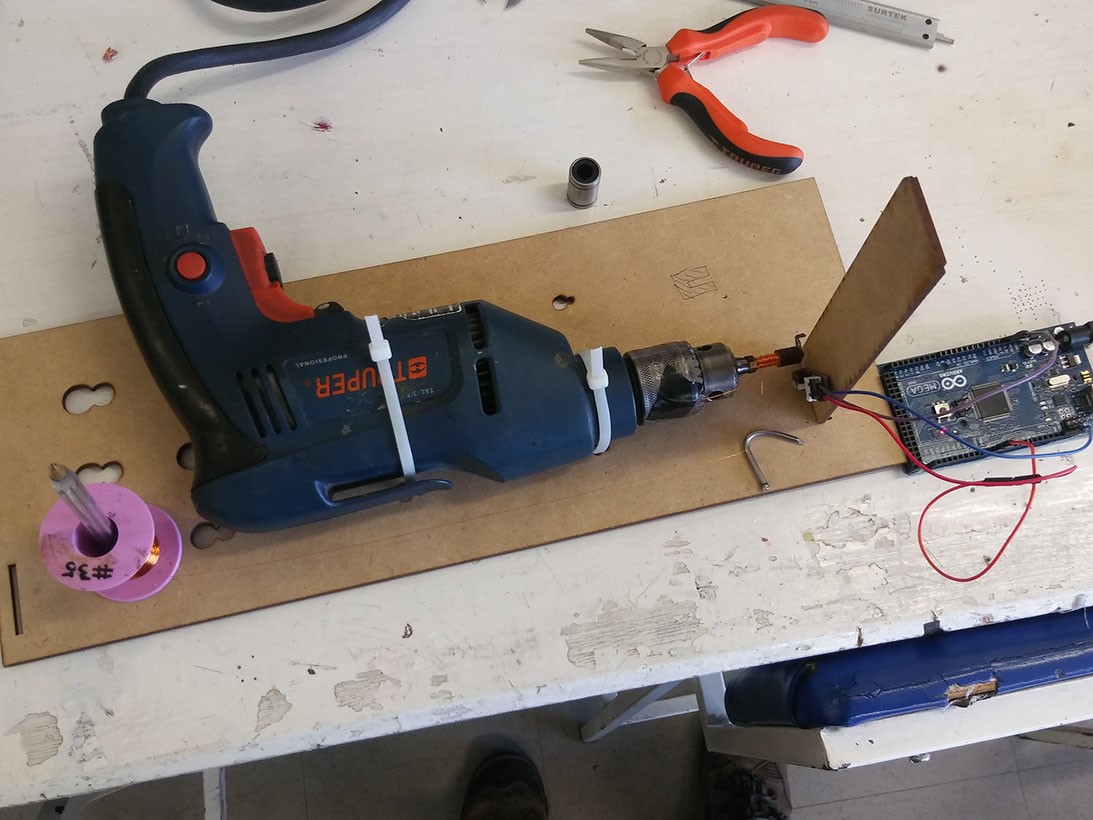
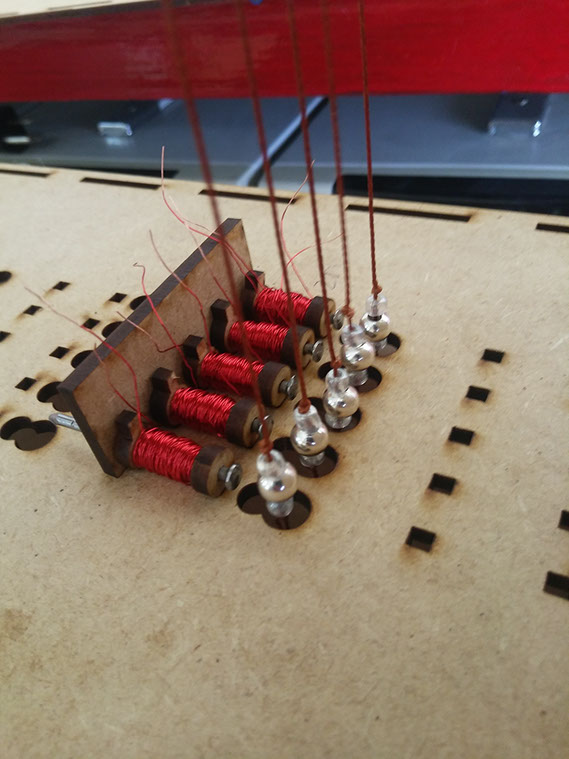
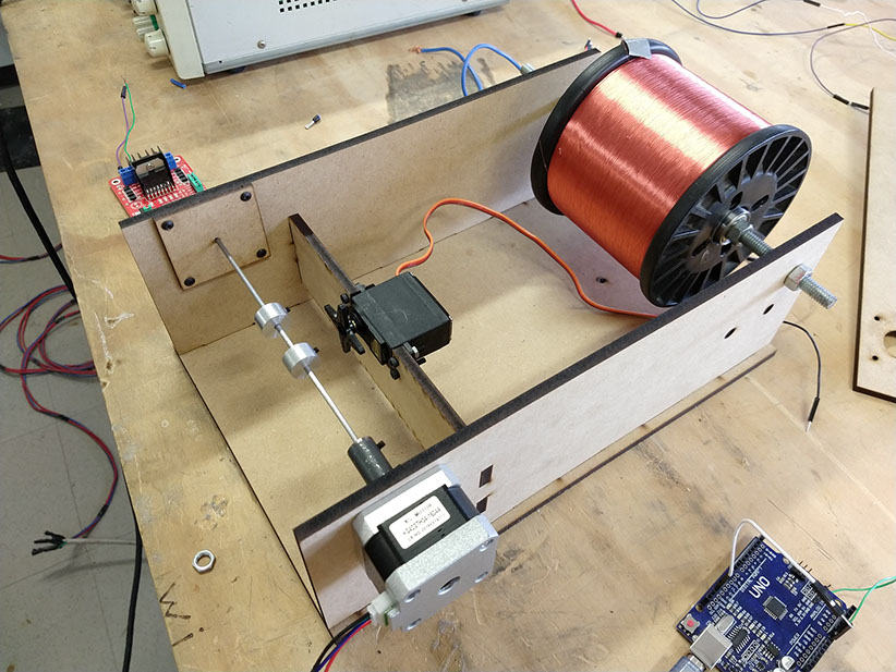
To make the next coils I used a drill, a limit switch and an arduino to count the turns of the coil to do quick tests for the current draw, magentic force and heat disipation.
With this type of electromagnet and making the ball ferromagnetic I can reduce the space a lot but now I need something to push the balls to the electromagnet becouse it is not stong enough.
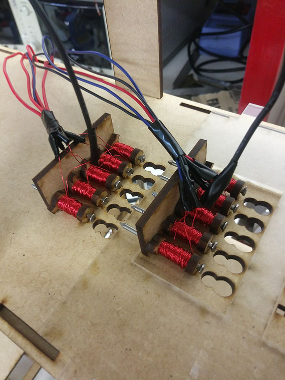
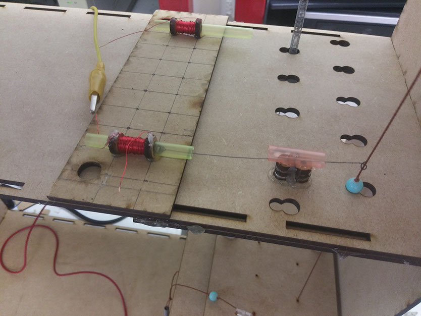
This is the first functional prototype, It works with individual switches and activates the number of electromagnet shown in the switch.
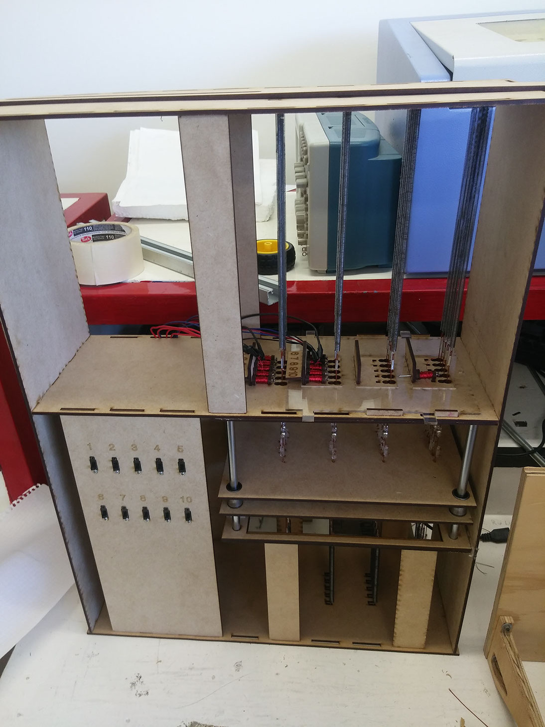
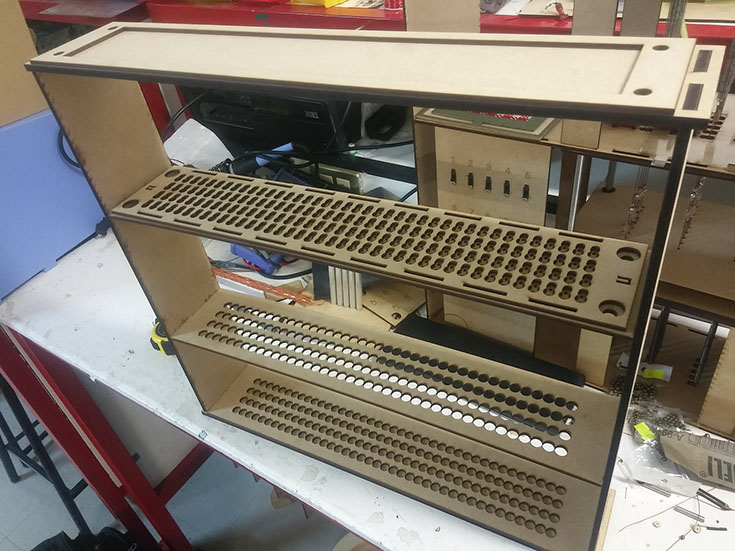
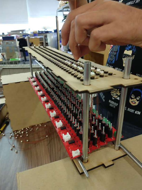
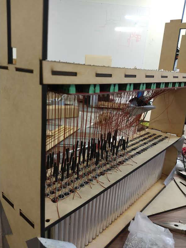
I took this mechanism and to make it a lot more space-efficient I rotated the electromagnets 90 degrees so the tip of the electomagnet is facing up and goes through the MDF.
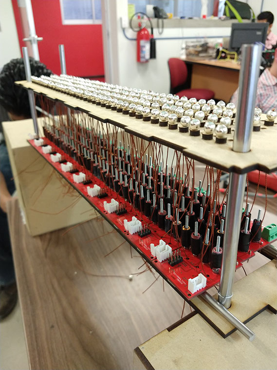
Now that I know I'll be needing 160 electromagnets (160 headdles) I need to make the coils as quickly and as consistent as possible, so with the help of a student named Rodrigo Salazar supervising the winding machine I designed we where able to make all the 160 coils.
For testing the electromagnets I used the board from week 14, I uploaded a program to turn the coil ON for 4 seconds and then OFF for another 4 seconds, with this program I can show how the mecanism works, take a look at the next video.
This is the program I used.
int mot = 2;
void setup() {
// initialize digital pin mot as an output.
pinMode(mot, OUTPUT);
}
// the loop function runs over and over again forever
void loop() {
digitalWrite(mot, HIGH); // turn the COIL on (HIGH is the voltage level)
delay(4000); // wait for a second
digitalWrite(mot, LOW); // turn the COIL off by making the voltage LOW
delay(4000); // wait for a second
}
You can download the board and the program HERE.
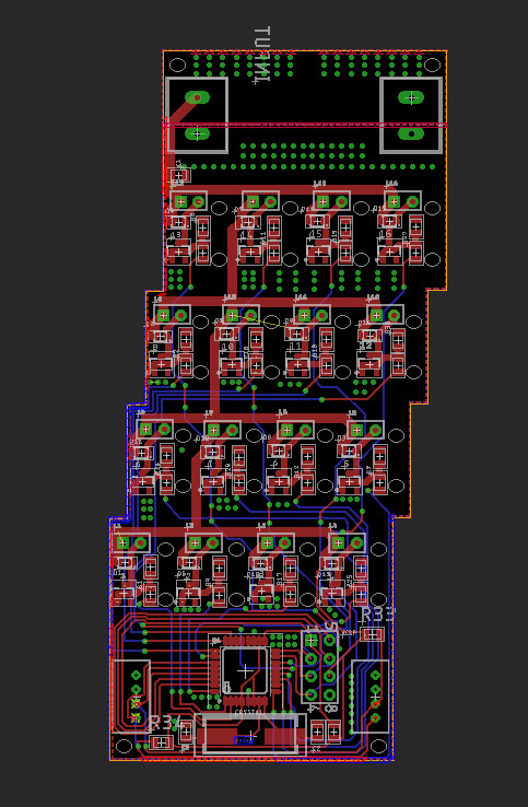
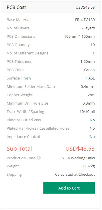
For making the circuits I tried to keep it inside de Fablab but we don't have the capability to make double sided 2 Oz circuits, and because it needs a lot of current (16 electromagnets per board working at 400 mA each) so I had to send the designs to providers, because I really want to show off the potential of this project with 160 headders at 4 headders per mm.
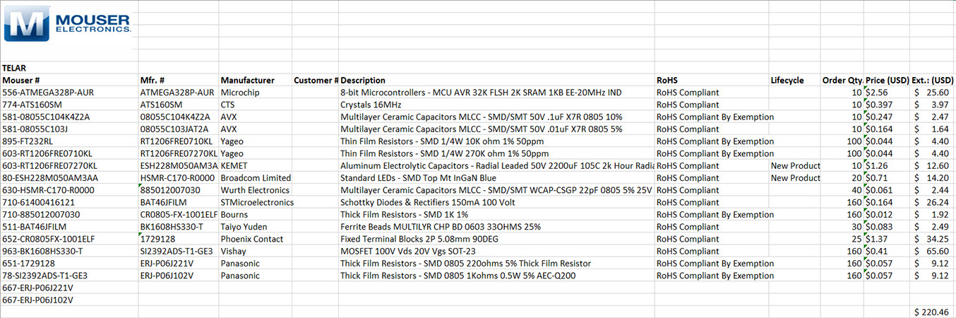
This is the component list, the provider was MOUSER electronics, you can click on the image below to acces the Excel list.
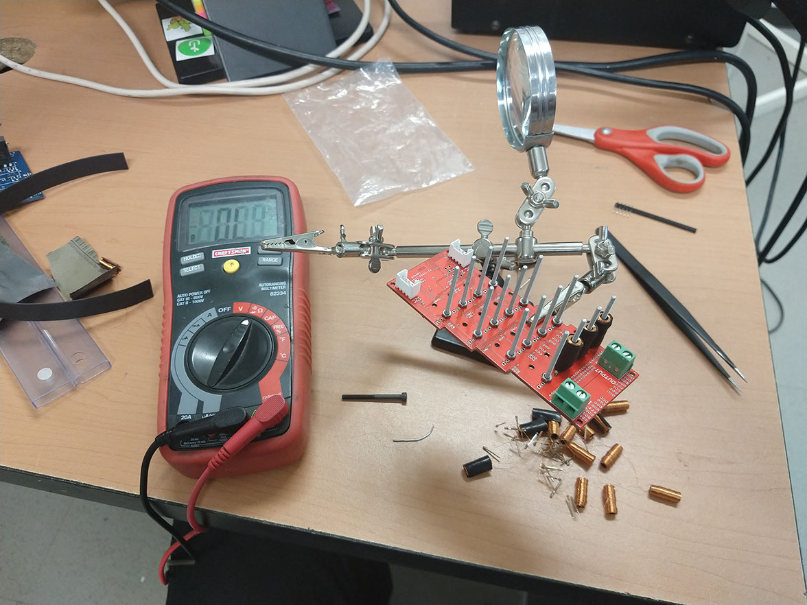
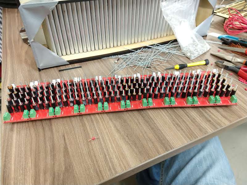
Soldering all the components was super hard, I asked for help to a student named Mario De los Santos, together we solder more than a 1,000 components to the boards.
To test the circuits the program made was turning ON and OFF specific electromagnets, if you watch the video at the bottom of this page called "funcion" you can see wich electromagnets are turned ON and OFF, it is kind of a zig zag pattern, and then the pattern changes to the other side.
int b1 = 4 ; //B16
int b2 = 3;//B15
int b3 = 12;//B14
int b4 = A3;//B13
int b5 = 5;//B12
int b6 = 6;//B11
int b7 = 7;//B10
int b8 = 8;//B9
int b9 = A2;//B5
int b10 = A1;//B6
int b11 = A0;//B7
int b12 = 9;//B8
int b13 = 10;//B4
int b14 = 13;//B3
int b15 = 12;//B2
int b16 = 11;//B1
int mov = 5000;
int mov2 = 10000;
void setup()
{
pinMode(b1, OUTPUT);
pinMode(b2, OUTPUT);
pinMode(b3, OUTPUT);
pinMode(b4, OUTPUT);
pinMode(b5, OUTPUT);
pinMode(b6, OUTPUT);
pinMode(b7, OUTPUT);
pinMode(b8, OUTPUT);
pinMode(b9, OUTPUT);
pinMode(b10, OUTPUT);
pinMode(b11, OUTPUT);
pinMode(b12, OUTPUT);
pinMode(b13, OUTPUT);
pinMode(b14, OUTPUT);
pinMode(b15, OUTPUT);
pinMode(b16, OUTPUT);
Serial.begin(9600);
}
void loop()
{
digitalWrite(b1, 1);
delay(5000);
digitalWrite(b2, 1);
digitalWrite(b1, 0);
delay(5000);
digitalWrite(b3, 1);
digitalWrite(b2, 0);
delay(5000);
digitalWrite(b4, 1);
digitalWrite(b3, 0);
delay(5000);
digitalWrite(b5, 1);
digitalWrite(b4, 0);
delay(5000);
digitalWrite(b6, 1);
digitalWrite(b5,0);
delay(5000);
digitalWrite(b7, 1);
digitalWrite(b6,0);
delay(5000);
digitalWrite(b8, 1);
digitalWrite(b7,0);
delay(5000);
digitalWrite(b9, 1);
digitalWrite(b8,0);
delay(5000);
digitalWrite(b10, 1);
digitalWrite(b9,0);
delay(5000);
digitalWrite(b11, 1);
digitalWrite(b10,0);
delay(5000);
digitalWrite(b12, 1);
digitalWrite(11,0);
delay(5000);
digitalWrite(b13, 1);
digitalWrite(b12,0);
delay(5000);
digitalWrite(b14, 1);
digitalWrite(b13,0);
delay(5000);
digitalWrite(b15, 1);
digitalWrite(b14,0);
delay(5000);
digitalWrite(b16, 1);
digitalWrite(b15,0);
delay(5000);
}
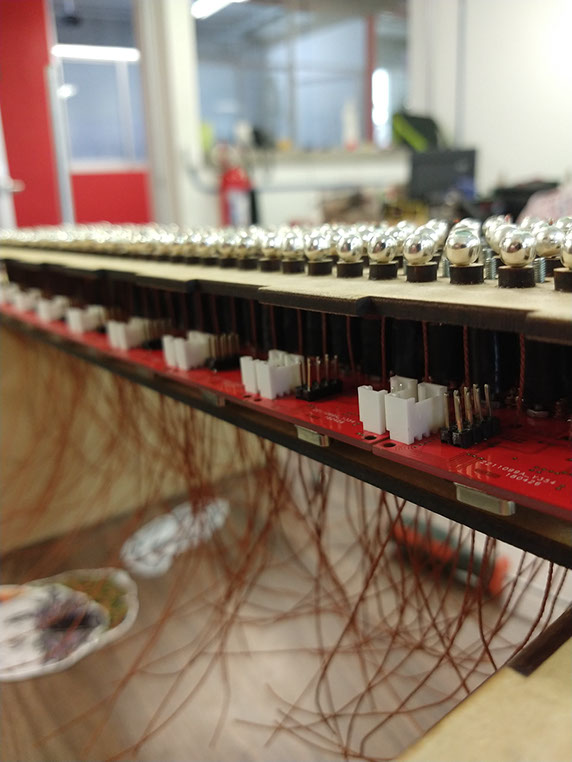
The screws act as the nucleus of the electromagnets.
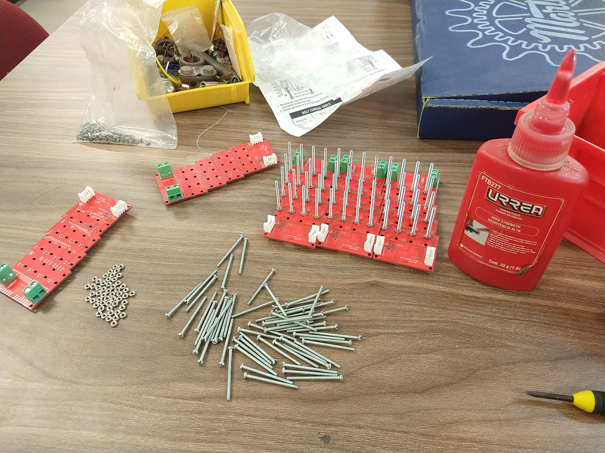
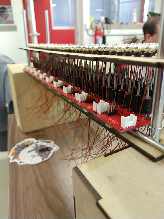
All the boards are connected together by voltage and ground terminals wich you can see as the green screw terminals in the image below.
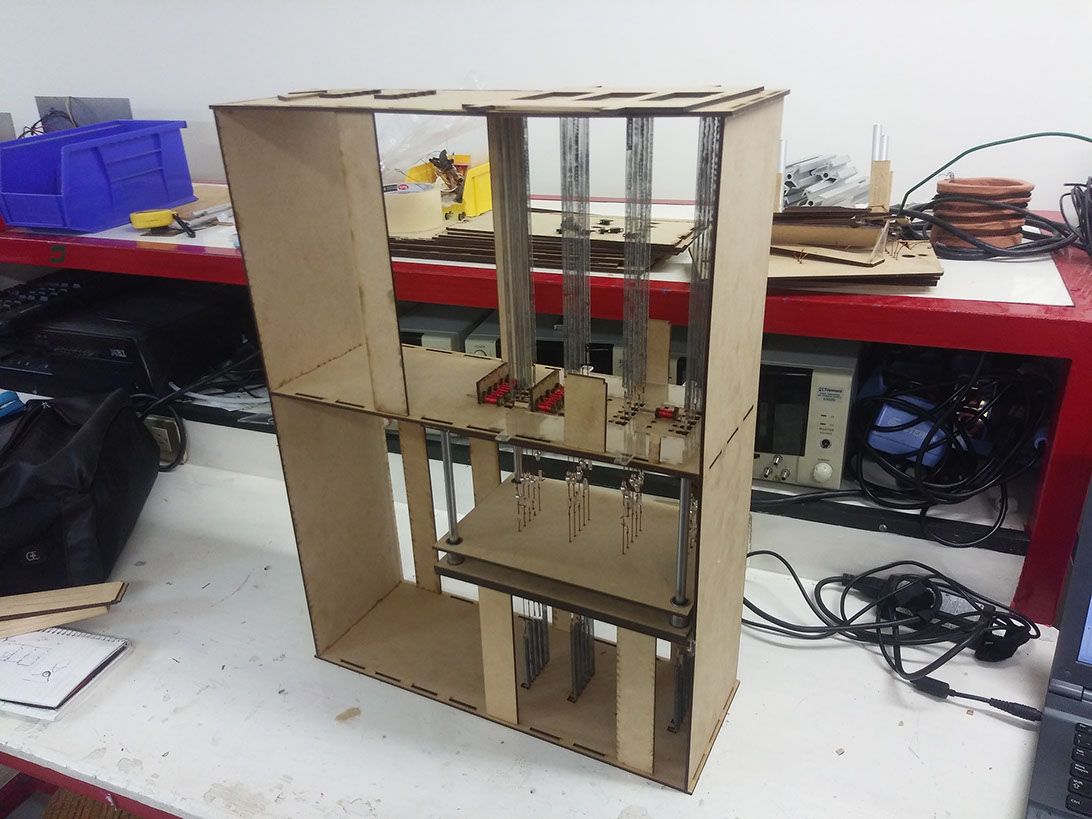
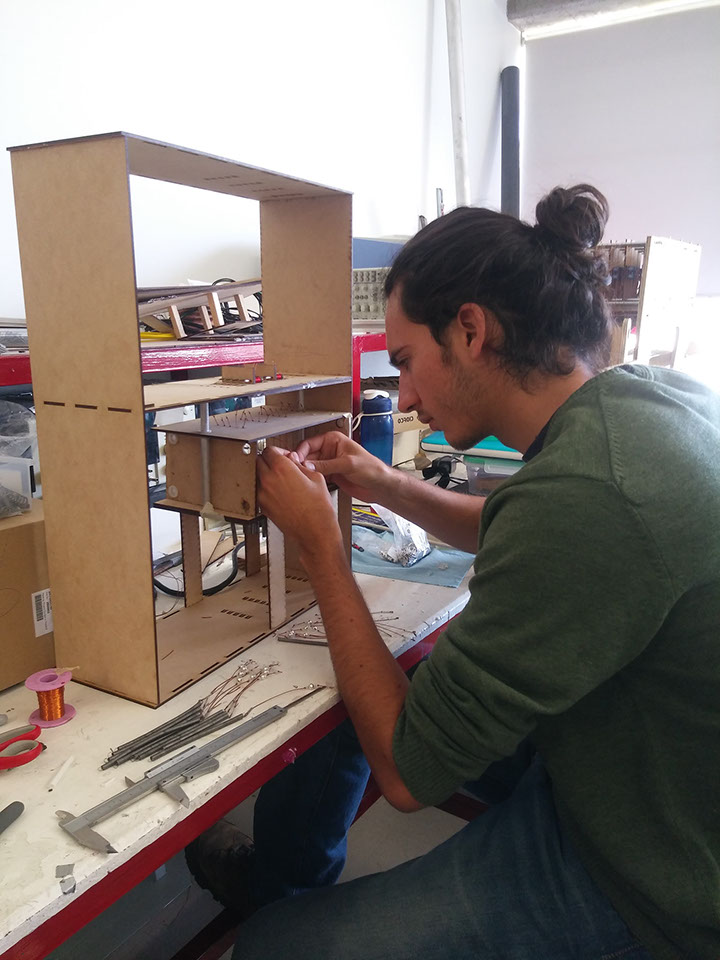
Pairing the electronics with the structure wasn't an easy task either, each string must go through the MDF and then through the circuits, then it is clamped to the headdles.
Bill of materials:
Circuit fabrication: $65.53 including shipping
Electronic components: $220.46
Laser cut: $25.00 including material
Linear bearings: $10.00
Aluminum tubes: $3.00
Headdles: 20.00
Bearing guides: $15.00
Magnetic wire: $15.00
Screws: $4.00
Metallic balls: $3.00
Strings: $1.00
Total: 381.99 US dollars.
If you would like to recreate this project for academic or personal porpouses you can download all the files necesary by clicking HERE