Week four: Computer-controlled cutting
Vinyl Cutting
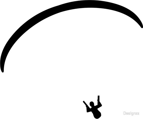
For the vinyl cutting I downloaded an image of a flying paraglyder, I used Adobe Ilustrator to convert the image to vectors which I could export in DXF format and cutted it in the CURIO.

Use the tool "pen" and trace the image using the curvature vectors, use as many curves as you need, don't try to do this quickly, take your time and the more lines you use, the better the quality.
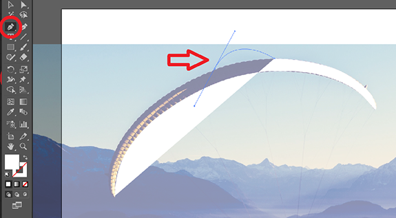
The pilot's body was a bit harder but with patience and trial and error I managed to get as many details as I could. This is a minimalistic design so I don't mind loosing the lines of the paraglider, I'm just focusing in the escence of paragliding
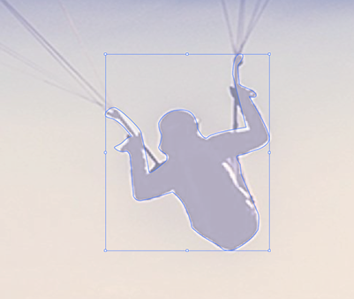
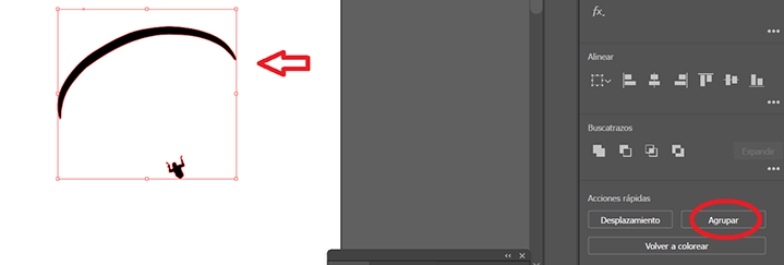
Hide the original image and change the filling color to black, then group both drawings so they become one. This step is not completly necesary but it helps you avoid loosing the reference in both drawings.
To save your drawing into something the cutter can read you have to export your file as a DXF format. You can then use the file for laser/vinyl cutting or engraving.
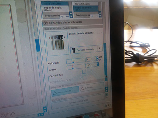
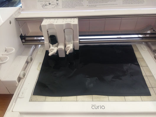
To set the CURIO I used the parameters we normally use with vinyl wich is 4 cm/s for speed and 10 for thickness, I pasted the vinyl in the surface of the curio and started cutting.
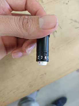
You don't need to set de zero X/Y machine because it will allways start to cut on the uper left corner, and for Z you have to set the number on the tool so it knows how much it will penetrate the material.
I then pasted it in my computer.
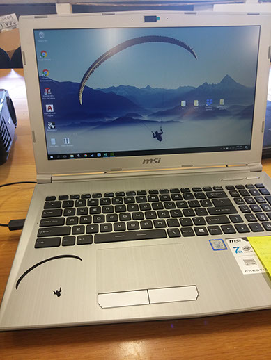
The result was really good IMO, I wanted something minimalistic but showing the escence of how a paraglider looks like mid-flight.
Press fit construction kit
The assignment for this week was to design and cut a parametric press fit construction kit.
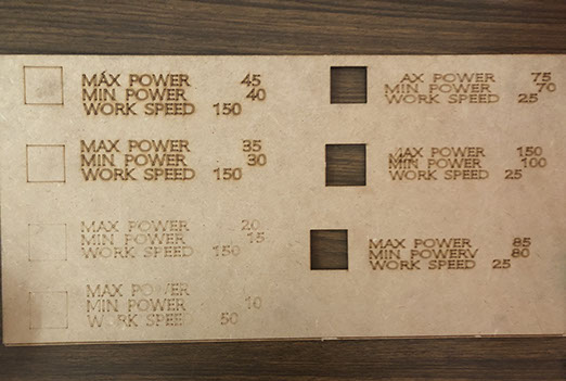
The first thing we did was to test the parameters in the lasercut which is a CAMFive Laser Up-Down System CO2 Cutter & Engraver CMA4032K, we did a test cut for 3mm MDF and these are the results.
We learned that the quality of the cut depends on the position of the laser relative to the table because the laser cutter needs to be alligned.
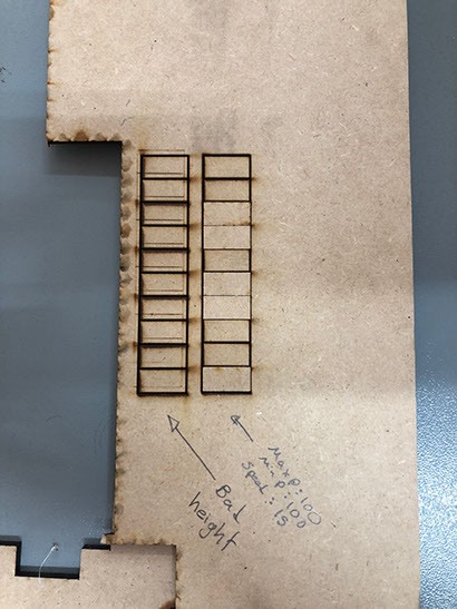
Then we did a test cut by cutting 10 consecutive rectangles so we could press them to each other and measure the space created, this space was about 2.9 mm, by dividing this space between the total of 11 spaces created for each cut we get that the kerf is about 0.26 mm, as I dont trust to much in this number because the laser isn't fully allinged, I used 0.2 mm as the kerf.
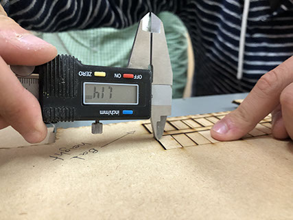
I used 65 for maximum power 60 for minimum and 23 mm/s for speed for cutting 3 mm MDF.
Design.
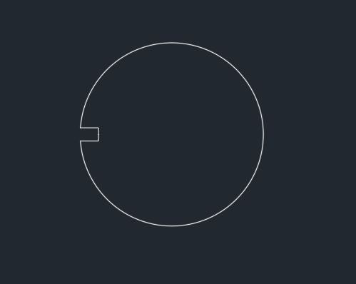
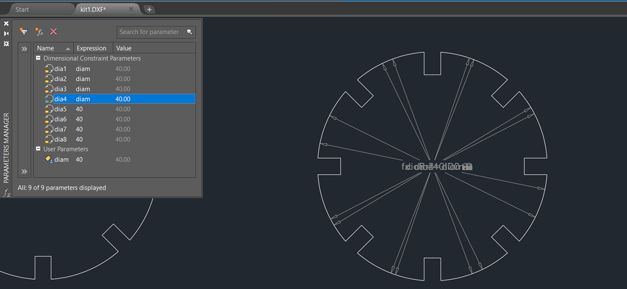
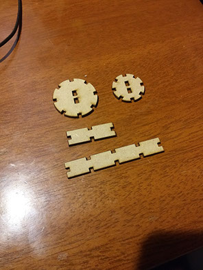
I wanted a circular piece with eight grooves and a center cut, so i first designed a circle and started to cut the grooves.
Then I gave it parametric constraints and used the "polar array" tool to cut the other grooves.
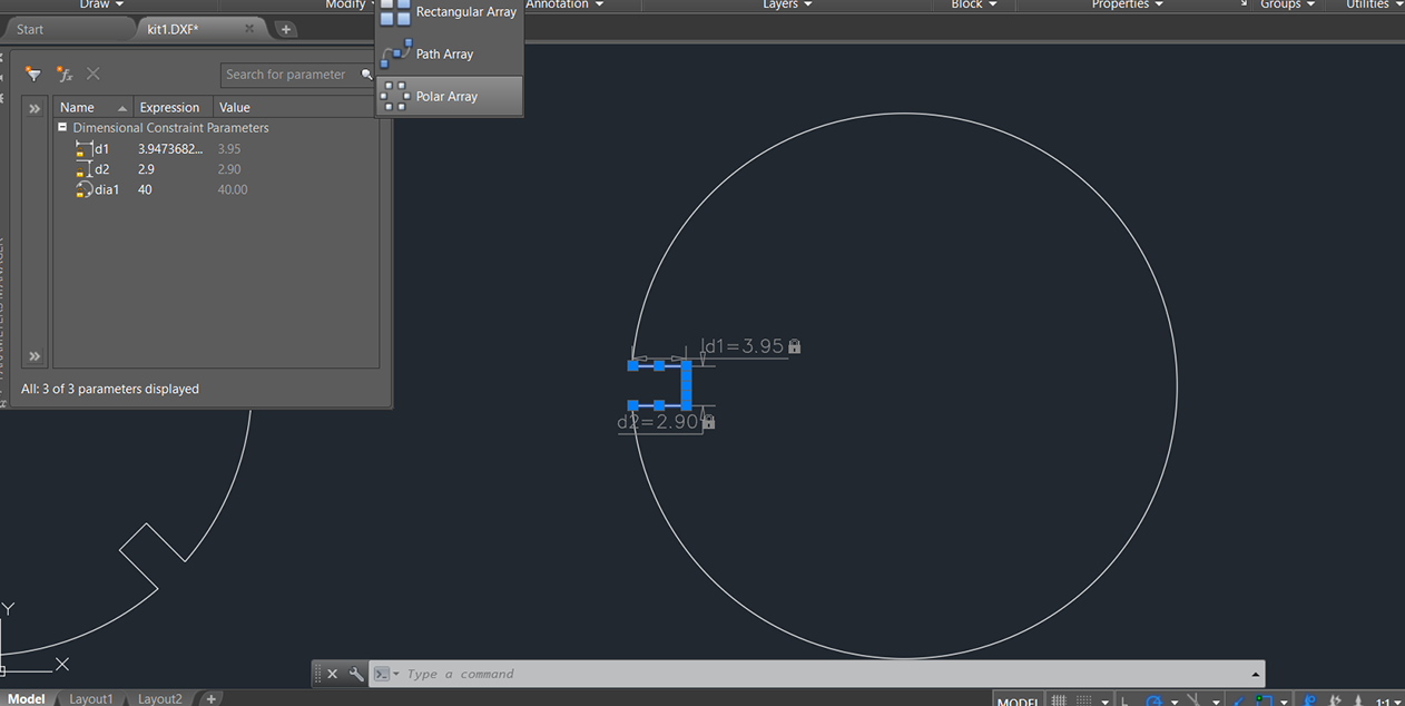
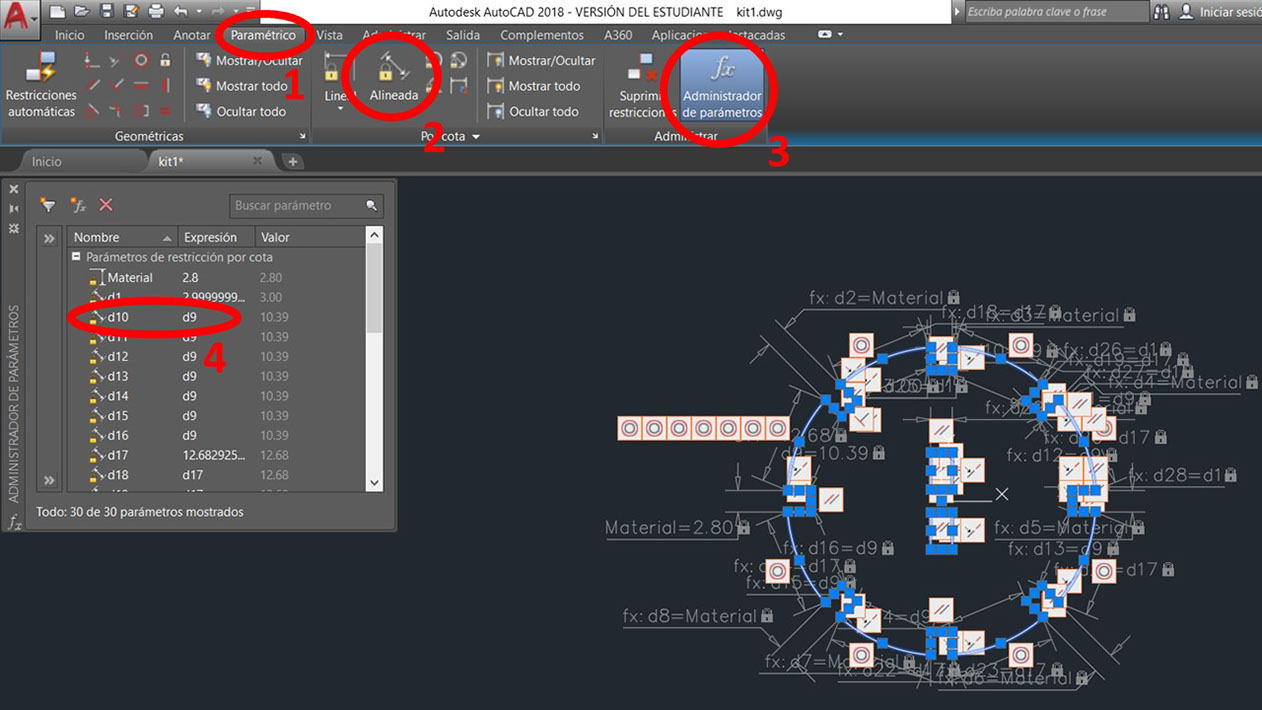
To link the meassurements of your design to parametric constraints you have to open the parametric tab (1) Choose constraint tool (2) Then make as many constraints as necesary to make sure you don't let any variable loose. Go to Parameter administrator and open the window (3) There you will find your constraints, you can modify them to be dependent to other variables, like d10 is iqual to d9 (4) so if I change d9 then d10 will change aswell.
This was the hardest piece in this kit, i made one a bit smaller and another two pieces for joining.
Laser Cutting
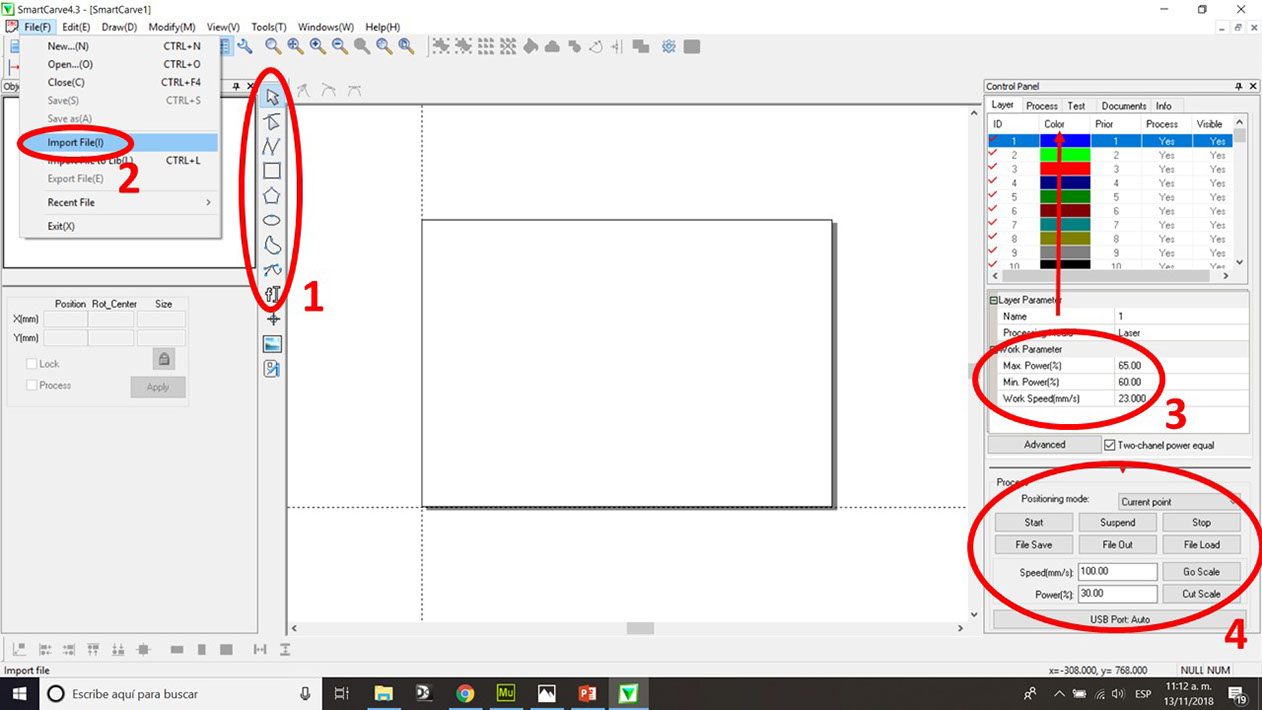
This is the software we use for the lasercut, it's called "smartcarve".
1. These are the tools to draw, I really don't use these, I like to design in another software and then import the DXF and just use it as a cutting software.
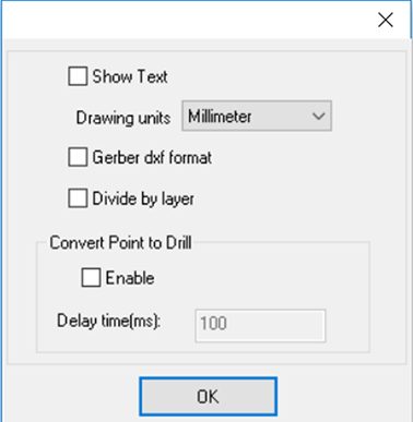
2. To import a file just click on "File(F)" and then "Import File(I)", you'll see a new window (next picture) where you have to choose the drawing units and then click OK.
3. Here we have work parameters, this is the power range the laser will be working at and the cutting speed. You have to do a test-cut as I previously did to know your own parameters.
4. These are the process tools, I normally only use the "Go scale", "Start" and "Stop" tools. "Go scale" is used to know physically the area of material you will be cutting in, the laser nozzle will draw a rectangle over your material.
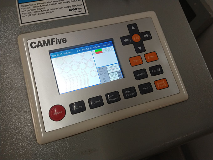
The next image on the right are the laser controllers, I used the arrows to set the X and Y zeros, and for Z you press "Z/U" center button and use the left and right arrow to upper and lower the table, the distance between the laser nozzle and the material must be 5 mm.
Then you just click "Start" on process tools and it will start cutting.
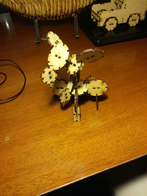
This is the complete set and here are some of the things you can build with it.
I even design two extra parts to build a car.
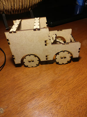
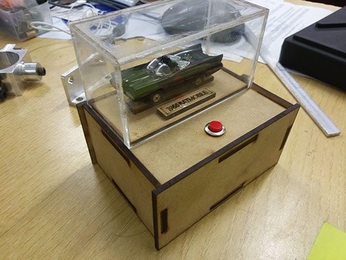
At first I didn't realize it was suposed to be a construction kit, so I made a parametric showcase for a batmobile and I think it's worth showing.