Week three: Computer aided design
First I started the 2D project by modeling a few sketches I had in mind for a little toy car showcase. I wanted to combine acrylic and MDF but I'll leave that to next week's laser cutting project, for now i'll just design the case.
I used the Autodesk license that Fab Academy provided to download autocad because I always wanted to learn how to use it.
I usesd the rectangle tool to make a five piece box for the acrylic part, I didn't want it to have press fit or any visible assembly points so they're just rectangles.
For the MDF box I want to use press fit but I still don't know how to calculate the kerf so I'll just leave the lips and modify them next week.
I already had the size of the car and a little button to make the car work (it's an electric car) so I based all the design in that.
I made four walls and a base all thinking in a 3 mm MDF sheet, again, I still don't have the kerf so these measurements might change next week.
I also took some time to make a little plate to give the showcase a little more personalization.
3D design
For the 3D project I wanted to do something useful and new. I practice some sports that use carabiners, like paragliding and rock climbing so I thougt in designing a quick release carabiner so I could keep my things secure and easy to access.
I used two diferent softwares, Solidworks and Catia so I could compare them. I tried to make the same steps in both.
I already had the idea of how big it was going to be and the mechanism used had to be simple and able to manipulate with just one hand, also I considered the part to be easy to manufacture using the mill and lathe.
I started by drawing a circle and extruding it to the desire lenght. Then using a face of the cilinder y draw another circle and extruded it aswell.
Then I extuded cut (pocket) two rectangles from a plane in both directions. I then also extruded cut another rectangle from the lateral face in one side.
Then I cut extrude (pocket) a rectangle and two holes to make the hinge and finaly filleted the weakest points to relief stress concentration.
I tried to make it with the least possible parts, so I ended up with a 3 parts assembly.
The next parts were easy, they're just a hook and a hollow cylinder so there's no interest in the process.
The cylinder works as a moving wall that blocks the movement of the hook, when you pull the cylinder up the hook gets free and rotates into the opening position.
There used to be a thread in two of the pieces but our printer wasn't capable of printing them correcly so I discarded the thread in the design.
Comments
Since I entered college I was fascinated for Catia, for me there was no other engineering software as good. Then I started working in the Fablab and here they prefer Solidworks, so a couple of months in, i'm in love with Solidworks and I am surprised I didn't took the time to learn it before. Solidworks is more visualy attractive and also has pop up menus when you make a selection and they are super super useful.
The final assembly looks something like this.
Click on image to download the part
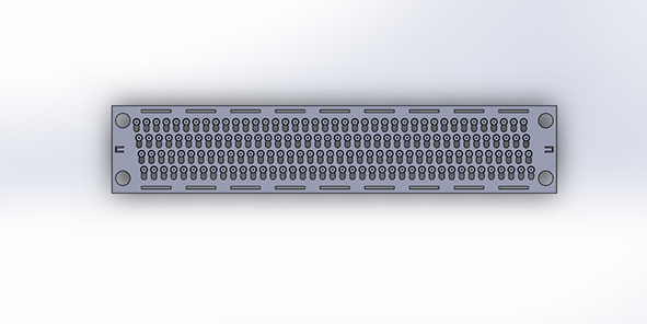
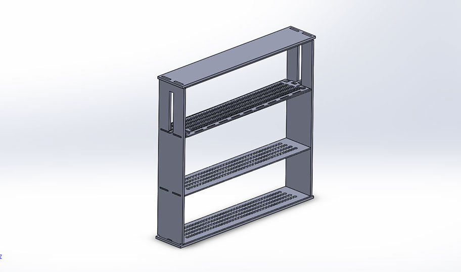
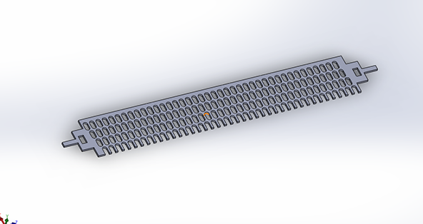
Final project
I made an assambly of what the fianl project should look like, as I explained in the final project section, it is a jaquard based digital loom that can control the design. I'm thinking on going with all MDF laser cut, we'll see.