Week twelve: Output devices
Group assignment: We measured the power consumption from the fan that powers my levitron project, at 8.4 volts it draws 89 mA or 0.089 A as it shows the video, which is not much.
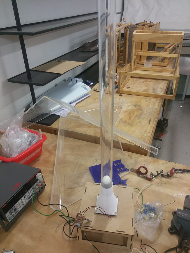
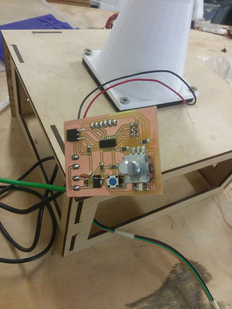
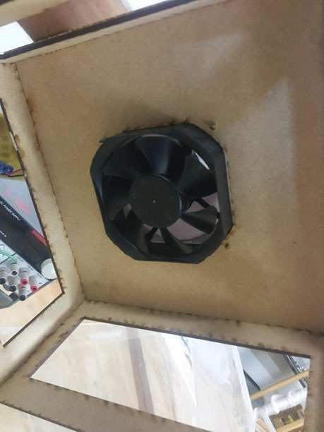
For Output devices I wanted something big and flashy, so I made a wind levitator, I made an MDF base with air intake space, putted a computer fan under it, covered the fan with a 3D printed nozzle and bought an acrylic tube.
The point is to mantain a styrofoam ball levitating inside the tube, you can either use the button or the potentiometer to control the speed of the fan.
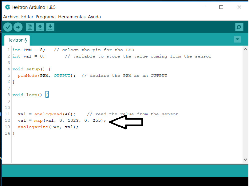
I used PWM to control the speed of the fan with the potentiometer, mapped from 0-1024 to 0-255.
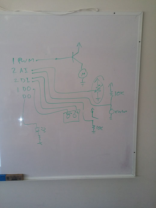
This is the first diagram made for this project.
Why I did this project? Well I recently took a friend to make an exam of his lungs and was told to blow on a stick, the stick conducted the air to a tube wich kept a ball levitating, so I thought it would be fun to make a sort of game with this principle.
I used:
- A button.
- A potentiometer.
- A LM3940 voltage regulator for 5v.
- A RFD16N semiconductro MOSFET.
- 2 screw terminals (1 for Vin and 1 for motor).
- An ATtiny 84.
- 6x1 pinheaders.
- 3x2 pinheaders.
- 3 0 Ohm resistors (for bridges R0, R1 and R2).
- 2 10 Ohm resistors (RBOTON and RTRANS).
- A 100nf capacitor (C1).
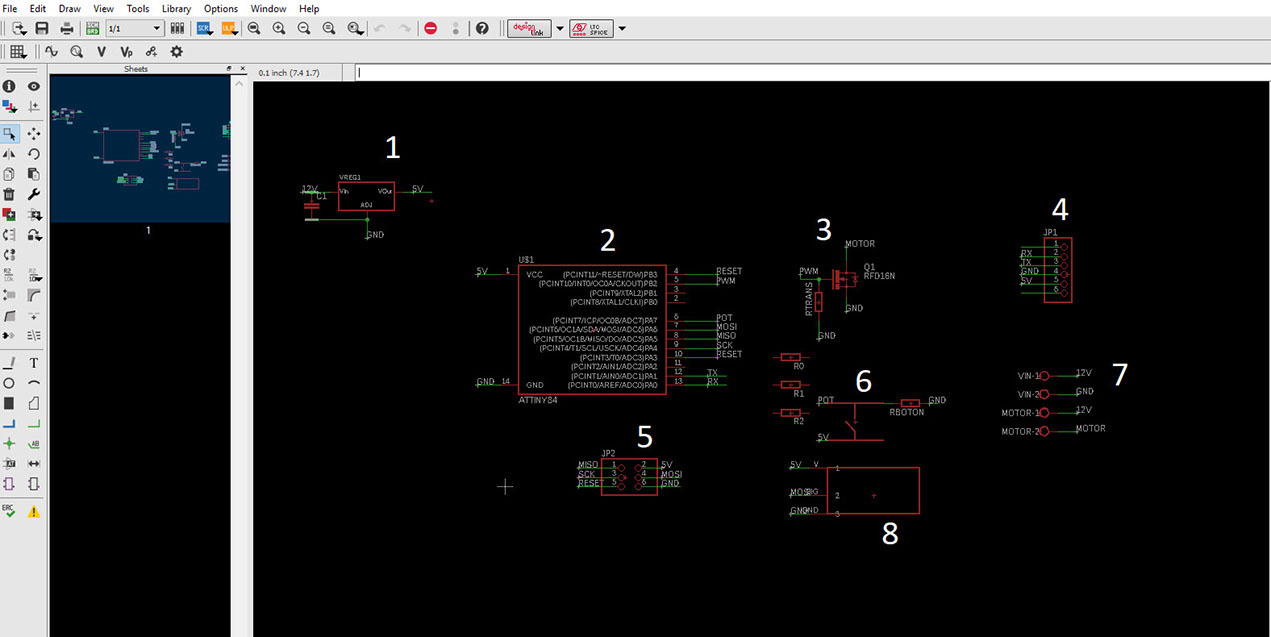
This is the Schematic:
1. This is the voltage regulator, it is used to get the source voltage used for the motor and lower it to 5V so all the electronic components can work.
2. This is the ATtiny84, it is used for controlling everything in the board.
3. This is an RFD16N MOSFET, it is used as a power gate, it draws energy from the source and opens every time the ATtiny84 gives it signal, with this component we are able to control the PWM to set the speed of the fan.
4. This is the female pinheaders to connect a bluetooth module for next week's assignment "interface and application programming.
5. This is the SPI connection pinheaders.
6. This is the button used for imputs.
7. This are the screw terminals for the Voltage source and the motor.
8. This is my potentiometer :) for imput also. (I'm so proud).
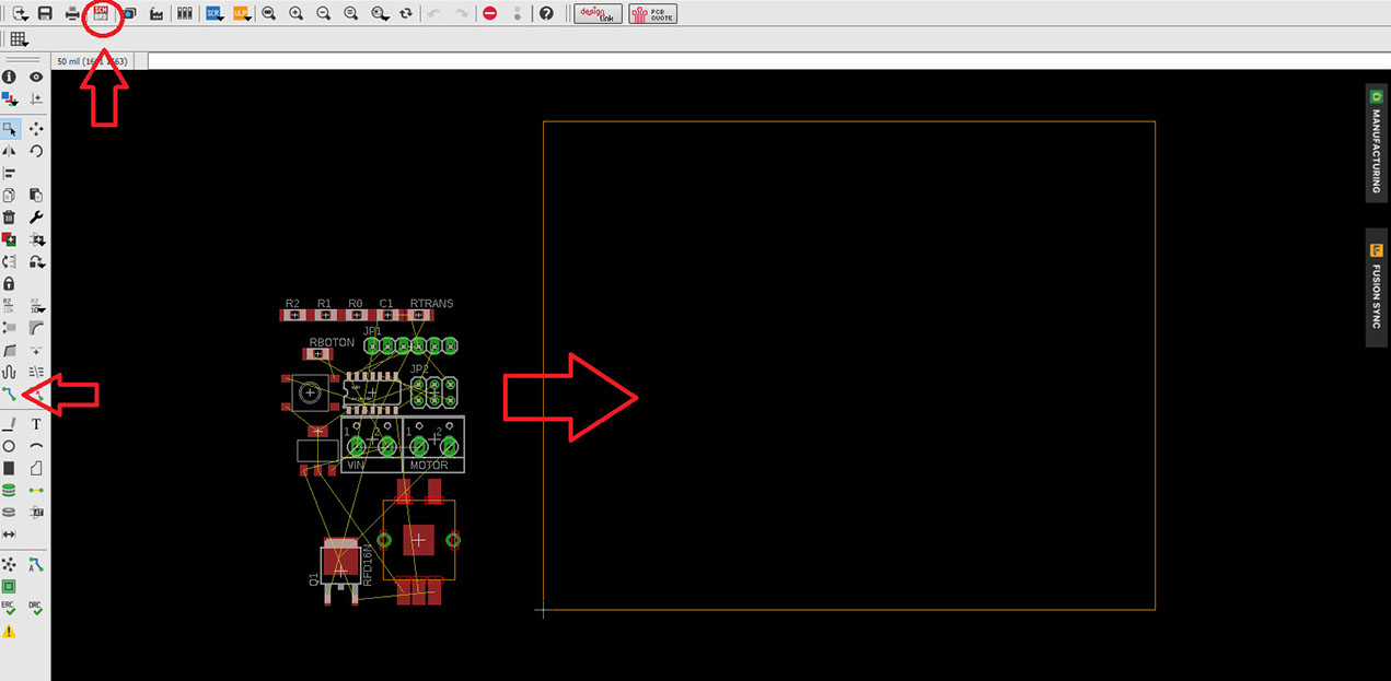
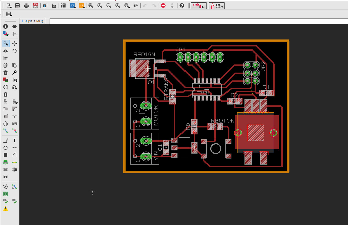
Change the window to board with the upper-right button, click on "ok" to start a new board based on the schematic, arrange the components as it is best suited for your board, and use the green path tool to connect everything by following the yellow lines between your components.
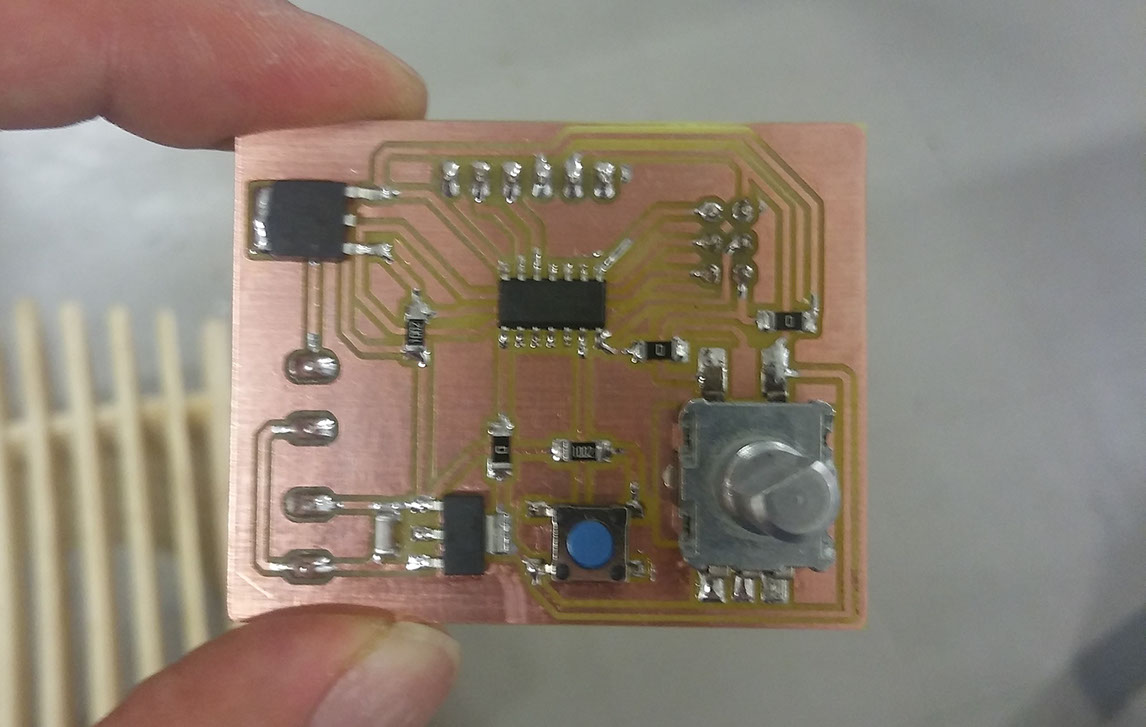
This is the completed board.
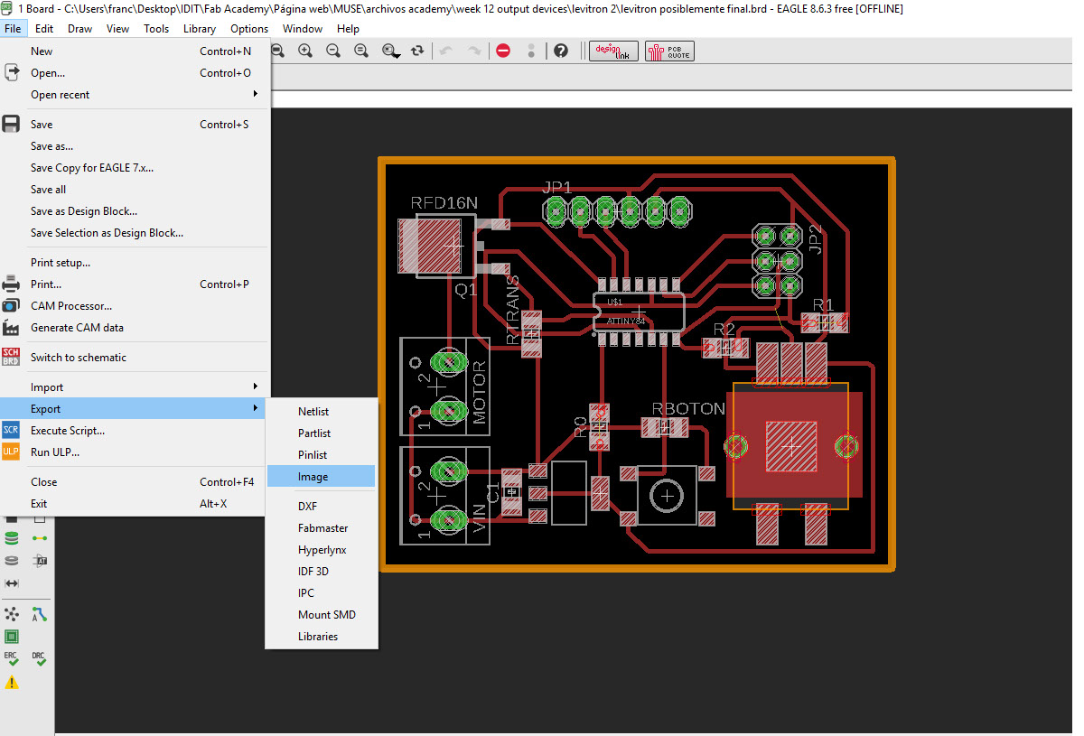
Export it as an image.
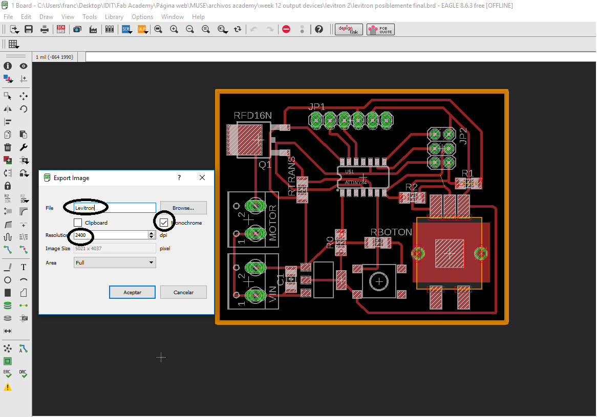
Don't forget to give it a name, mark the monochrome box and put the highest resolution.
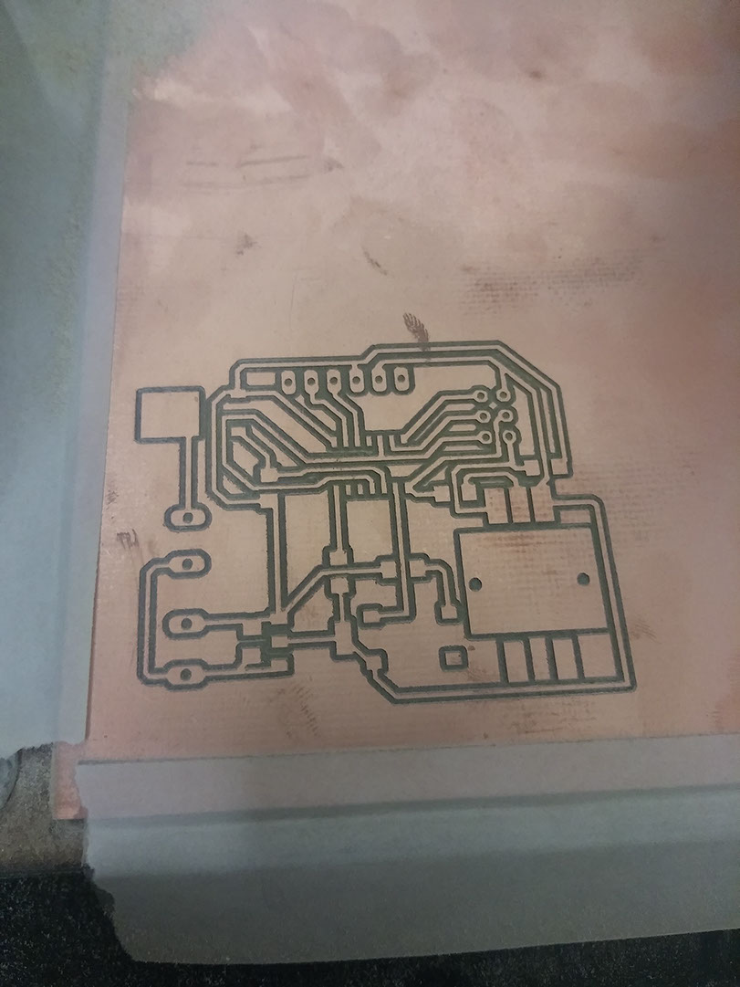
Load the .PNG file to the modela and engrave it with the parameters, speed: 1 mm/s jog: 1mm diameter: 0.3 mm offset: 3 overlap: 0.5 error: 1.1 Intensity:0.5 Z: -0.1 mm
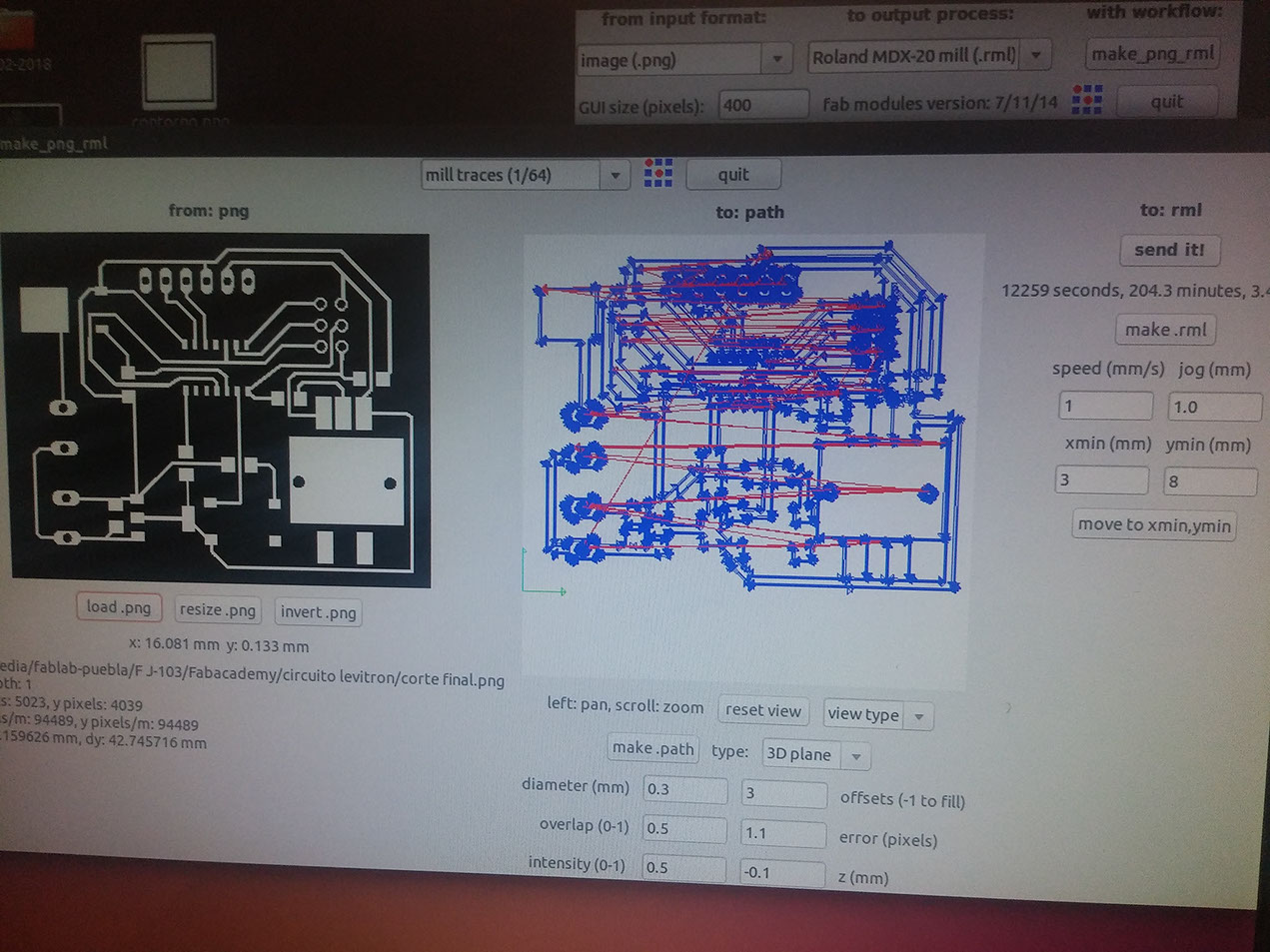
If everything went fine it wold look like this, now run the cutting program.
For the program I used the program from arduino: https://www.arduino.cc/reference/en/language/functions/analog-io/analogwrite/ and changed the variables, and added a mapping from the potentiometer to the PWM.
Download the files here
My experience with this project was really rewarding, I learned that complicated things such as PCBs have to be made slowly and with patience, I made a lot of mistakes, this board should have been the same board as the "inputs" one, but as I explained in WEEK ELEVEN a lot went wrong, even in this board I forgot to put a capacitor from the output of my voltage regulator, I had to solder a normal capacitor right in the pads.