Electronics Production
.jpg?crc=529461652)
.jpg?crc=4236108755)
.jpg?crc=535830914)
.jpg?crc=3955986675)

.jpg?crc=344801797)
.jpg?crc=3779411804)
.jpg?crc=338592587)
.jpg?crc=4107698684)
.jpg?crc=4040880606)
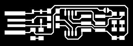
1.- Doing the PCB.
To begin with this assignment I chose a design from the ones that were provided in the class description. I liked this design , and it seemed easier to make, so I chose to Use it for the practice.
I went to the machine we were going to use for milling. I proceeded to paste a copper plated board with double sided tape. Then we opened the program Terminal Konsole from the PC connected to the machine and typed sudo fab, and the password required for the program to start. I am aware this is an older version, but it is the one our Fab Lab is using at the time, so I had no other choice.
I imported the .png files to the program, and was told it already had the proper parameters for the traces, so i went ahead, clicked make "path", then make .rml then send it. It took about 14 minutes to mill the traces. Then I exchanged the tools, so I could proceed to cut it, using the same origin. I imported the other file, set the parameters to tool width 0.79 mm, gave it the origin I was using for the other one, set the speed to 2 instead of 4, and repeated the same steps to send the file to the machine. I have no pictures for the cutting part of the process because my phone's camera stopped working, I am currently considering asking some of the people taking the Fab Academy in Puebla to lend me their pictures of this part.
2.- Soldering.
To do this, I first needed the components that I was going to use. I went again to this site to look for the list and the person in charge of the Fab Academy in our Lab gave them to me. The list of components is as follows:
- One ATiny 45.
- Two 1k ohms resistors.
- Two 499 ohms resistors.
- Two 49 ohms resistors.
- Two 3.3v zener diodes.
- One 10mF capacitor, this one was supposed to be 100nF but we did not have any, so we had to bodge it together.
- One green LED.
- One red LED.
- Two sets of 3 pin headers, we did not have the appropriate ones shown in this site, but we had to bend the tips and bodge them together, again.
I had a little bit of experience soldering, so I was not completely lost on how to star. However, it was my first time soldering surface components, so I was a little nervous because of how tiny they are. I started by taping my PCB to the table I was going to solder in so it does not move or I do not move it by mistake. I started with soldering the ATiny 45, because it was the closest one to the center and had the most places to solder. Then I began moving outwards with soldering the components, except for the pins, I put them in last because they were just too big and they would just get in the way. To solder the components I first left a bit of solder in the pad, and then heated it a bit, when it was melted I placed the component so it held for a bit, then Soldered the other side and revisited the first side so I could complete the process.
I was so concentrated with soldering that I forgot to take pictures of all of the process, but after I finished soldering the pins, I applied a bit of solder to the usb connection parts, so it could be easily picked up by the port.