Assigment:
-Group assignment:
Characterize the specifications of your PCB production process
-Individual assignment:
Make an in-circuit programmer by milling the PCB, then optionally trying other processes
We used Roland Modela MDX-20 to mill the PCB, I used Brian's design to build the FabTinyISP. This machine is a mini CNC milling by its size is commonly used to mill PCB. Using this machine is a way to do not contaminate the planet using other methods to print PCB like inmmerse your PCB on ferric acid.
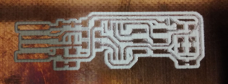
First I download the images of the FabTinyISP from this page: http://fab.cba.mit.edu/classes/863.16/doc/projects/ftsmin/index.html
There are 2 images, one is for engrave and the other is for cut also there are one tool to engrave and one for mill.
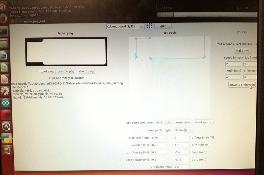
I opened the program to use the modela to start engrave my FabTinyISP, I putted the next parameters to engrave it, click on make.path, click on make.rml and send it
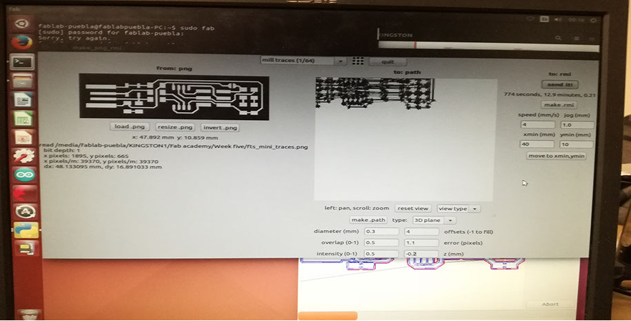
This window appears when I clicked on send it
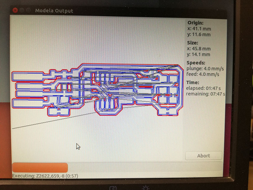
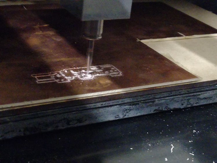
Now I uploaded the other image to start milling the PCB and change to the other tool to milling and putted other paramethers because is another tool.
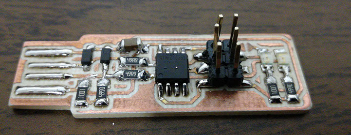
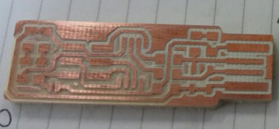
This was the result of my PCB
Soldering the electronics
I used the next components:
-1x ATtiny45 or ATtiny85
-2x 1kΩ resistors
-2x 499Ω resistors
-2x 49Ω resistors
-2x 3.3v zener diodes
-1x red LED
-1x green LED
-1x 100nF capacitor
-1x 2x3 pin header
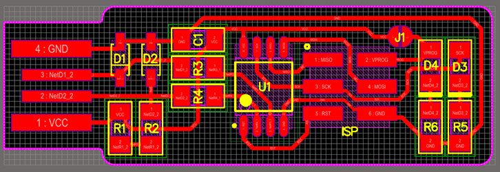
I followed the board image below as a reference for component values and placement. First I soldered the ATtiny because I thought is going to be more difficult than the others and it was like that. It was my first time soldering on board, I learned that first you need to put some solder on the pin on the board and after that put the component and solder one side.
This was the result soldering all the components. For my first attempt I think it was not to bad, well I think so...