16
Machine design
What I learned: How to actuate and automate the machine.
Sources and inspiration used:
What I did:
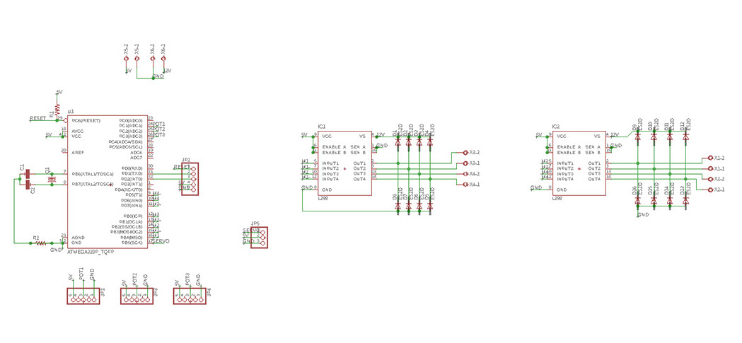
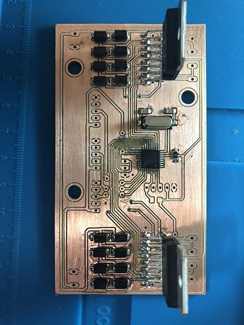
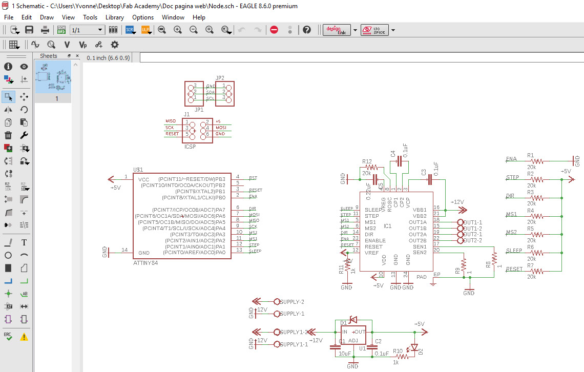
I designed the SCH file. with guidance of the fab. Below you can find the SCH file used for the machine. The components used are: Atmega328, two multiwatt 15 lead (L298), a crystal, diodes, resistors, pinheads, capacitors, clamps.
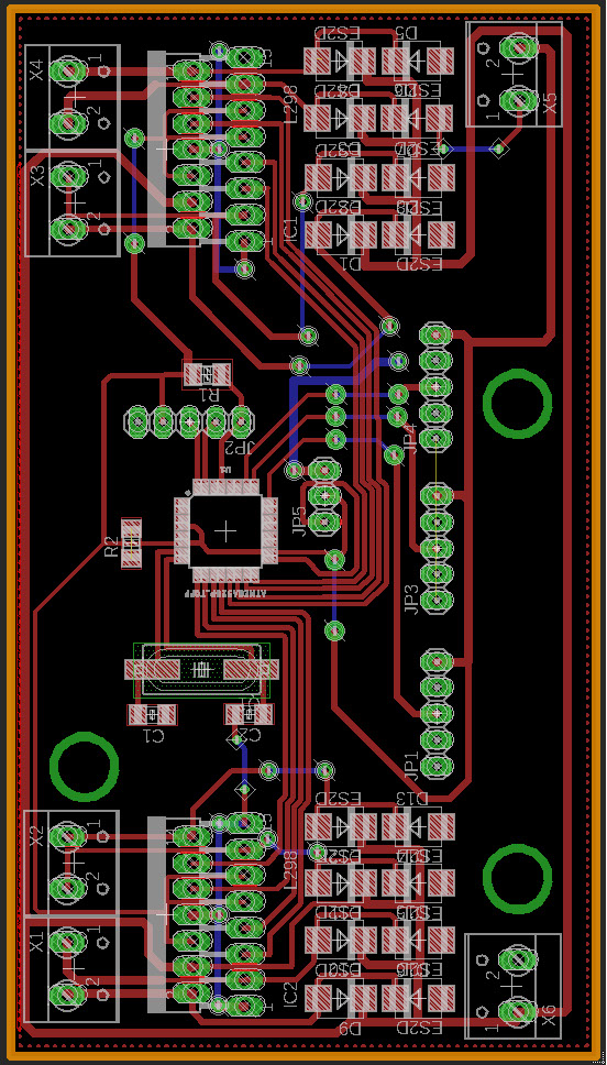
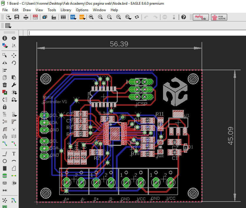
I was also part of the process to create the BRD file, both files can be found below.
Click on the image
to download file
Click on the image
to download file
We also needed to use the circuit that was already made in an earlier assignment, you can quickly access that assignment by clicking in image below.
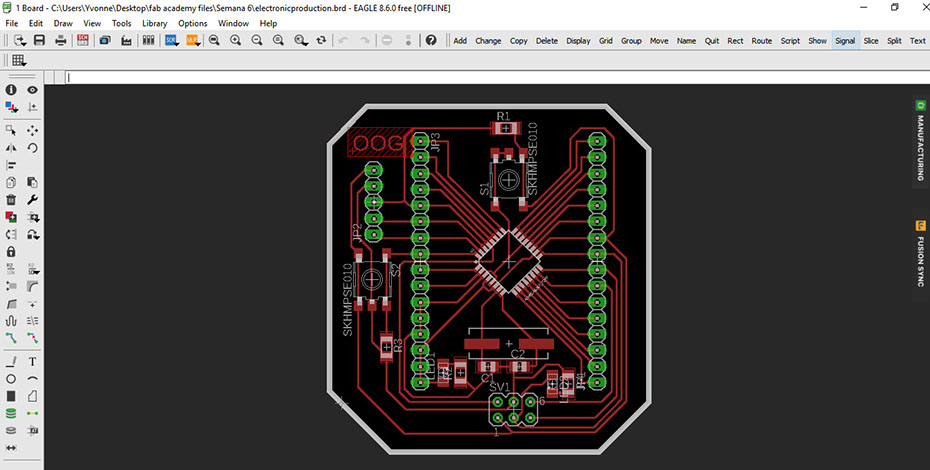
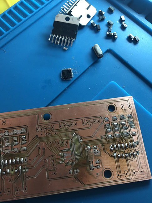
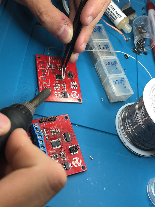
It is important to note that to make the first circuit pictured in this site, we had to consider the second one. So that all the pins fit in the write way. We started welding the components to the new circuit, but we realized that there was a mistake in the routes, due to the material the routs didn't work. So we had to un-weld everything and cut again the circuit, below you can see the process.
In the video below you can see us testing the machine. These tests consist of testing from the serial monitor. A number is pressed and then the motor moves. If you press another number, it stops. Everything happens from the computer, direct in interface, for that reason we do not use a button.
Click on the image
to download file
Click on the image
to download file
This is the master programm
This is the slave programm
#include <Servo.h>
#include <Wire.h>
char code='x';
int cmd=0;
Servo act;
void setup() {
// put your setup code here, to run once:
act.attach(9);
Serial.begin(9600);
Wire.begin();
}
void loop() {
// put your main code here, to run repeatedly:
if(Serial.available())
{
code=Serial.read();
}
if(code=='0')
{
Wire.beginTransmission(0x1);
Wire.write(3);
Wire.endTransmission();
delay(1);
Wire.beginTransmission(0x2);
Wire.write(3);
Wire.endTransmission();
delay(1);
}
if(code=='1')
{
Wire.beginTransmission(0x1);
Wire.write(1);
Wire.endTransmission();
delay(1);
}
if(code=='2')
{
Wire.beginTransmission(0x1);
Wire.write(2);
Wire.endTransmission();
delay(1);
}
if(code=='3')
{
Wire.beginTransmission(0x2);
Wire.write(1);
Wire.endTransmission();
delay(1);
}
if(code=='4')
{
Wire.beginTransmission(0x2);
Wire.write(2);
Wire.endTransmission();
delay(1);
}
if(code=='5')
{
act.write(45);
}
if(code=='6')
{
act.write(55);
}
}
#include "TinyWireS.h" // wrapper class for I2C slave routines
#define i2c_addr 0x2
int stp=1, dir=7, ms1=2, ms2=3, slp=0, ena=10;\
byte rcvd=0;
int i=0;
void setup()
{
pinMode(stp, OUTPUT);
pinMode(dir, OUTPUT);
pinMode(ms1, OUTPUT);
pinMode(ms2, OUTPUT);
pinMode(slp, OUTPUT);
pinMode(ena, OUTPUT);
digitalWrite(ms1, LOW);digitalWrite(ms2, LOW);
digitalWrite(ena, LOW);digitalWrite(slp, HIGH);
digitalWrite(dir,1);
TinyWireS.begin(i2c_addr);
}
void loop()
{
if(TinyWireS.available())
{
rcvd=TinyWireS.receive();
if(rcvd==1)
{
digitalWrite(dir,1);
digitalWrite(stp,1);
delay(10);
digitalWrite(stp,0);
delay(10);
}
if(rcvd==2)
{
digitalWrite(dir,0);
digitalWrite(stp,1);
delay(10);
digitalWrite(stp,0);
delay(10);
}
if(rcvd==3)
{
digitalWrite(dir,1);
for(i=0; i++; i<200)
{
digitalWrite(stp,1);
delay(10);
digitalWrite(stp,0);
delay(10);
digitalWrite(stp,1);
delay(10);
}
}
if(rcvd==4)
{
digitalWrite(dir,0);
for(i=0; i++; i<200)
{
digitalWrite(stp,1);
delay(10);
digitalWrite(stp,0);
delay(10);
digitalWrite(stp,1);
delay(10);
}
}
}
}
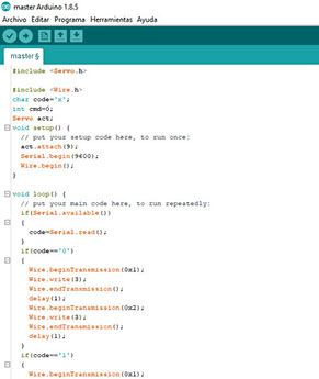
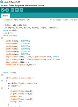
I also helped program the master and slaves programs so the machine could work, below is the explanation of what each program does.
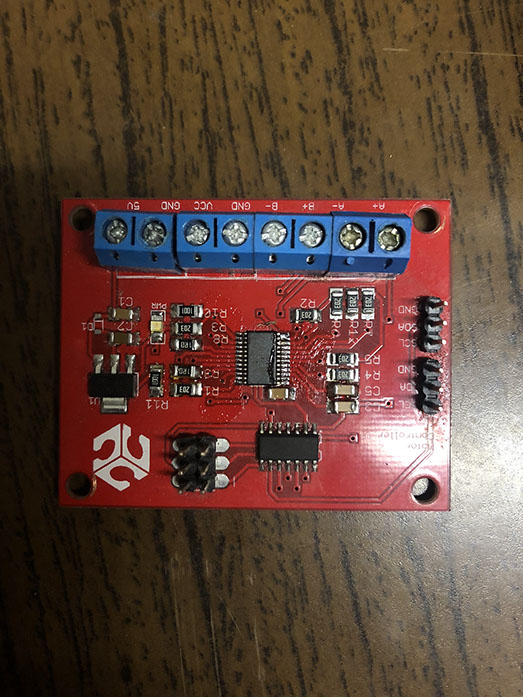
We used a local Fabhouse circuit, the design is from Fablab Puebla but it was sent to Ryspee to be manufactured.
Characteristics of the FabHouse circuit:
Base material FR-4TG130
in two layers
PCB dimensions Width: 1.6 mm
red soldermask with white legends
Hasl finish
2 ounces of copper
6000 spaced
Minimum drill of 24000
microcontroller A4982
45x56 mm
Click on the image
to download file
Click on the image
to download file
The components are: pins, ATiny84, resistors, capacitors, screw terminals,TSSOP-24, IC1.