3

Computer aided-design
What I learned:
I learned to used AutoCAD and Solid Works, to design 2D and 3D models. In each software I designed both 2D and 3D parts.
Sources and inspiration used:
For the 2D model in AutoCAD (Excercise 13): https://autocadparatodos.blogspot.mx/2013/10/EjerPropBas-01.html For the 3D in AutoCAD (Excercise 8): https://autocadparatodos.blogspot.mx/2015/01/EjerProp3D-02.html For the 2D model in SolidWorks: https://www.youtube.com/watch?v=gmUwrFUzL6k
For the 3D model in SolidWorks: https://www.youtube.com/watch?v=3CGKno1Djmk
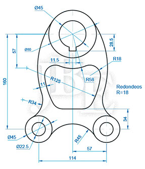
What I did: 2D in AutoCAD
I started by drawing a vertical line of 160, and a horizontal line of 57 to the right. You must click twice enter to release the tool. Later the center and diameter option is used to make the circles. After drawing the arc that must be tangent to the diameter 80, its center must pass through the point at a distance of 57, the radius of the circle is 136. For this, the Offset tool is used. Afterwards a third circle of 96 is drawn, the intersection of both objects is the center of the circle of radius. 136 you are looking for. With a button to delete or cut the unnecessary parts are chosen to remain alone with the desired arc. The option fillet with a radio and multiple option is used to form the figure. New and use the Trim command to trim unnecessary objects. After using the mirror command, all the objects are selected from right to left and the mirroring loop passes on the middle axis, and the image is copied. Again, the fillet with a radius of 45 is used to join the arch between both sides. Again the line is executed to generate the upper notch in the circle, it moves to the intersection. The trim and enter command is executed again to finish.
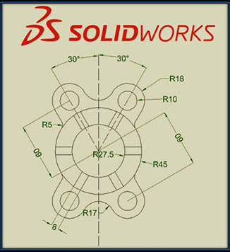
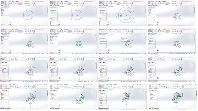
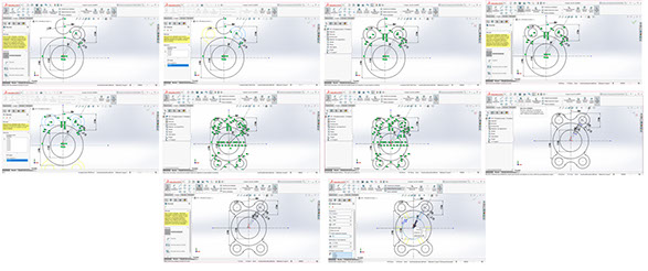
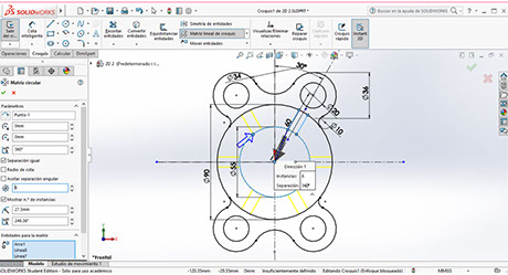
What I did: 2D Solidworks
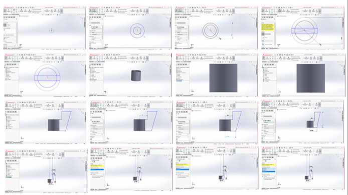
You start by putting SolidWorks in millimeters. A sketch is generated in a raised plane, a circle with radius 22.7 is generated. An intelligent dimension with a diameter of 55 millimeters is drawn, an exterior circle with a diameter of 90 millimeters is drawn. Vertical and horizontal construction lines are plotted with respect to the circles. At 30 ° of the vertical axis, a vertical line is constructed. Afterwards, a circle with a diameter of 20 millimeters is drawn. The distance between centers must be 60 millimeters. After an arc of radius of 18 millimeters, to draw it a circumference of 36 millimeters is drawn. You can see that there is a rounded, to make them and draw a circle with a diameter of 10 millimeters, the circumference will be tangent to both circles, choosing the circles with click on control and the place where they will be tangents adding to the relationship, click on accept. After a semicircle is drawn first with a circle centered on the vertical axis, with a diameter of 34 millimeters, both circles are tangent, then the first and second circles are selected with control and with the tangent option. Subsequently, the excess lines are eliminated. Then on the vertical axis with symmetry of entities, the arc and the circumference and the rounded part with respect to the vertical axis are selected to draw the missing part. Subsequently, the remaining entities are cut. Again the previous step is made but this time with horizontal axis. Finally, there are parallel lines with a space of 8 millimeters, the equidistant option is used, the entity is selected bilaterally and the remaining entities are cut out. It is important in linear sketch matrix, circular sketch matrix with circumference parameter, choose the lines and define them 6 times.
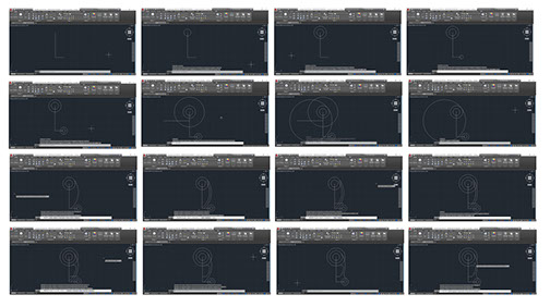
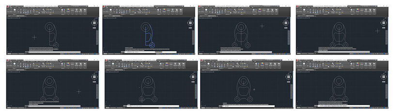
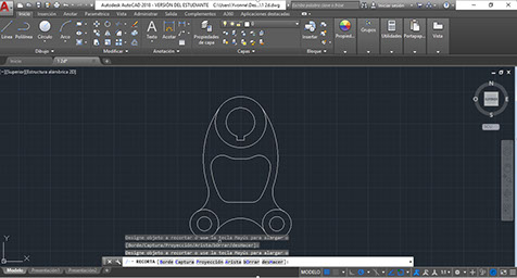
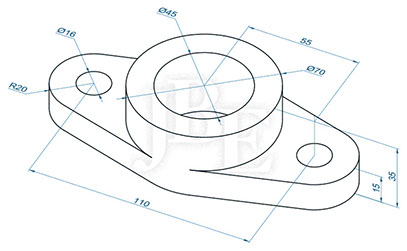
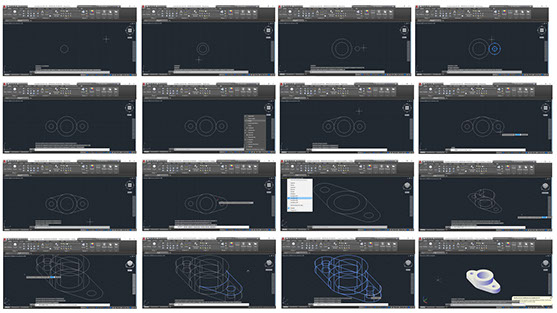
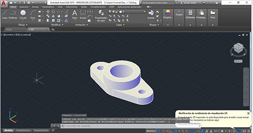
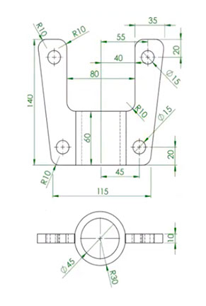
What I did: 3D AutoCAD
I began by drawing a circle of diameter 45 and another of radius 35. The circle command is executed to elaborate the above. Then at a distance of 55 two circles are drawn, one of radius 8 and another of 20, again press 20, move to the right and dial 55, with this the center is typed. It is copied by choosing both circles and moves to the left by typing 110 and enter to end the command. With the line the tangent is made, that option is activated and the center and dial are deactivated. Later the line is executed to join the pieces. Subsequently, with Trim, unnecessary arcs are eliminated. To perform the extraction, an isometric southeast view is chosen. The Presspull tool is chosen, and inside the area it goes upwards and typed 35 and enter. Repeats with 15 and with 15, double enter. With Solid Union, the parts are selected and enter is pressed. Subsequently, the excess parts are eliminated. It expands to the virtual conceptual style and the exercise is over.
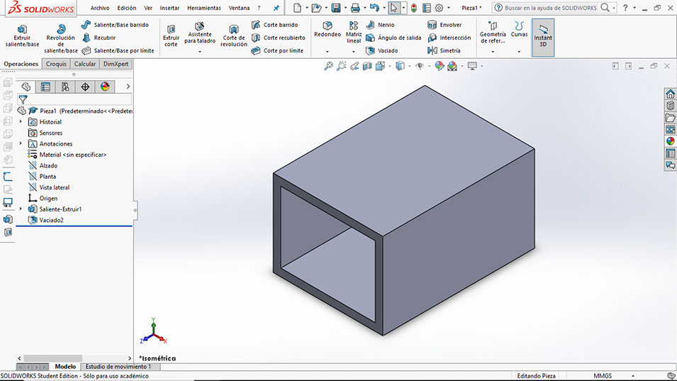
What I did: 3D Solidworks
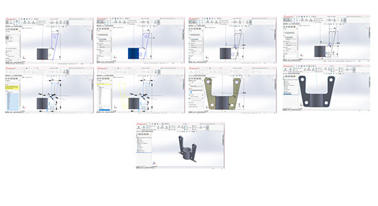
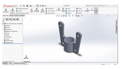
I began by drawing the hoop of the top view. In sketch two circles are drawn, one with a diameter of 45 millimeters and the other 60 millimeters. Subsequently a center rectangle is made up to where it collides, the excess entities are cut out. To release the tool, you must click on escape. The excess parts are eliminated and the circumferences with the straight parts remain. Later in operations the piece is extruded. The next step is to create a plane that passes through the middle of the circle and in a raised plane the symmetry is drawn with respect to the center. Constructively, then a line becomes a part of the drawing. Later, the figure is drawn with straight lines and inclinations. Once you have the above, the means of each part of the drawing are given. Then with sketch rounding the entities are rounded. Subsequently the circumferences are created, these have a diameter of 15 millimeters. The distance between the circles and their respective diameters is defined with intelligent dimension. With symmetry of entities, everything that has been drawn and placed with respect to the vertical axis is selected to generate the mirror of the figure. The width of the piece is changed to 10 millimeters, in the medium plane.
Click on the image
to download .dwg file
Click on the image
to download .dwg file
Click on the image
to download .sldprt file
Click on the image
to download .sldprt file
Right click and save as here
to download .dfx file
Right click and save as here to download .dfx file
Right click and save as here to download .dfx file
Right click and save as here to download .stl file
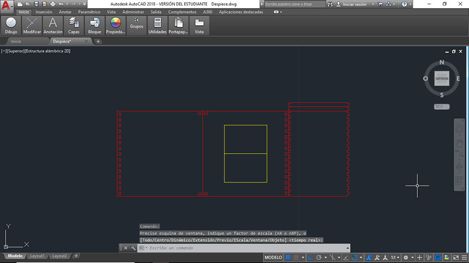
Below you can find the sketch made to model the parking lot for my final project. It consists in two parking spaces and walls, so the laser light can be seen either if the parking space is available or not. This model will be cut with laser in MDF.
Click on the image
to download .dwg file
Right click and save as here for .dfx file
Many say that SolidWorks is more effective when working on designs in three dimensions and AutoCAD is the way to go for 2-dimensional design. Personally, I really liked both software’s, I had a lot of fun learning how to use them. I agree that Cad is easier when modeling in 2D, I liked Solid because the interface is way easier to use, I like the colors (white background). I must say that even though I think Solid is easier, Cad runs faster in my computer… sometimes Solid would crash. I like using CAD for models that will be cut in laser, and I like to use Solid for models that will be 3D printed.

I also made a 3D model of what the parking model might look like.
Click on the image
to download .SLDPRT file
Right click and save here to
to download .STL file