4
Computer- controlled cutting
What I learned:
I learned the process to design n Autocad things that can be cut in vinyl or with laser. I also learned to make those designs parametric so I can change once measure and the whole piece changes it's size without loosing ti's shape. The designed made for laser cut is press fit, that means that there is no need to use glue, nails or anything else to put its pieces together.
Sources and inspiration used:
To create the star I made use of the following tutorial: https://www.youtube.com/watch?v=xxvmPXbsocY
For the press fit design I found inspiration in the next link: https://drive.google.com/file/d/0B3r-ySD7arYCVExiSnl3TW5fdEk/view
For the construction kit, I found inspiration in the next link: http://unitbcn.com/
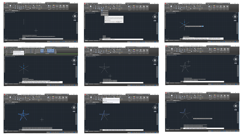
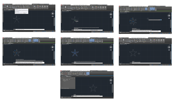
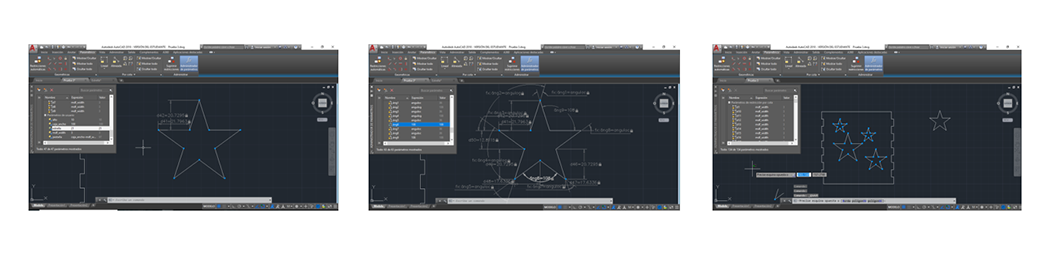
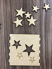
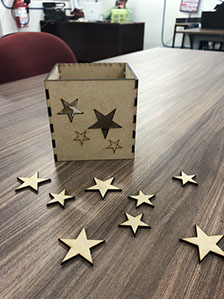
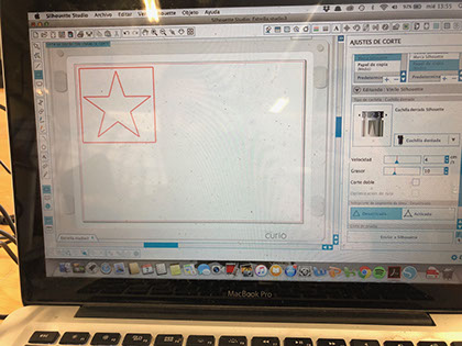
What I did: I started to draw a star in Autocad. To create a star in Autocad, you start using the line tool, a line is made to give you the measure you want. In this case we started with a line of 30. The line is given a polar matrix, the line is selected after Enter and then the rotation point is selected, so it has the polar matrix. It is reduced from 6 to 5 so that the star has 5 points. Again with the line tool the points are joined as shown in the image. Press F8 to place the line diagonally. The excess lines must be trimmed, selected with the trim tool. Then a polar pattern is applied to the drawing, the image is selected and Enter is pressed, then the rotation point is chosen. This is how the star is obtained, it looks a little disordered so again the number must be adjusted to 5. Finally, the internal zone is selected and deleted. It is important to join all the sheets so that a complete figure is formed and you can cut it in vinyl.
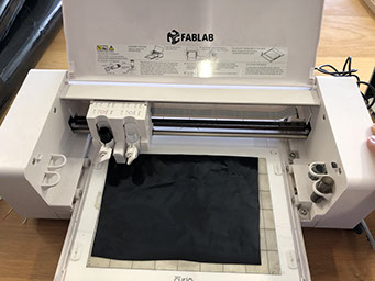
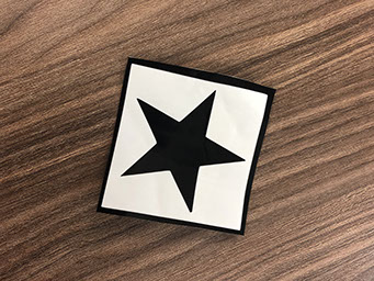
The machine used is a Curio vinyl cutter, and it uses the Silluette Studio Software. First the design screen is blank, to show the guides, you must select how cut border in settings. First I had to export th file made in Auto Cad, to a .dxf extension, so the vinyl machine recognizes the figure. I used the curio software to import the file and afterwards I set both the size as the parameters for the machine. That means define how tall or width will my star be. The software is quite friendly , just click on the blade icon to open cut settings. There you can select the material type .Once I have everything done, I placed the vinyl paper and made sure that there were no bubbles. I send the machine to cut the design and afterwards I have a star.
The parameters used to cut in Curio were 4 cm/s for speed and 10 for thickness. I used those because I was told by my instructor that they are the ones usually used for vinyl.
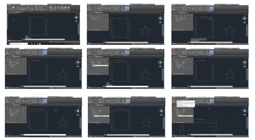
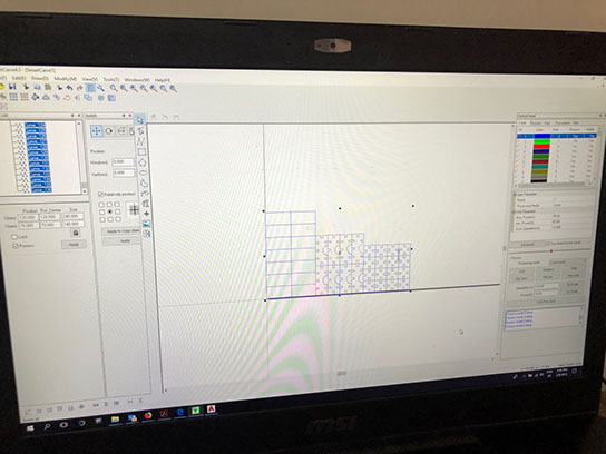
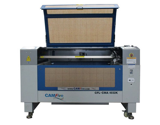
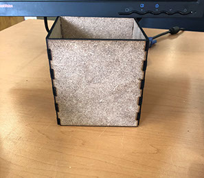
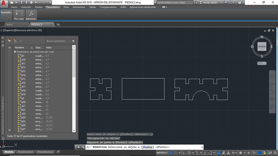
What I did: I started to work in AutoCad, I first decided to make one side of the box (all sizes are the same so as long as the first one is right all the others should fit perfectly). I decided to make the box 100 units long and each fit 10 units, but later on I learned that I should use the width of the material I will use and so I changed it to 3 units. After the drawing was finished, in the parametric ribbon, I used the coincidence tool to link all the line together, so that when I change one measure, the lines don't separate one from another. After that I used the lineal tool to create restriction parameters by dimension. I had to chose every single line, after being done with doing that, I created user parameters. The parameters I made were one for the straight line above and under the figure, one for the width of the material and another for the length of the fits. Once I was finished with doing that, I changed the numbers in the user parameters and I gladly saw that the shape resized itself without losing its form. As a group we first characterized the lasercutter we made test to see how the machine works. Sadly the box didn't fit perfectly, it was a little loose on the edges. The machine we used is a CAMFive Laser Up-Down System CO2 Cutter & Engraver CMA4032K Working Area 40x32" Cutting and Engraving Machine for Wood Acrylic and More. To create a parametric file in AutoCad you just have to choose the parametric option and click on the line you want to make it able to change its size or material later on. Its a process that takes a bit of time at the beginning but once its done it makes your work a lot easier. Using the parametric option means that the piece you make can be scalable. To do the parametric design you have to click in the parameters management and also apply a restriction tool while selecting the line you want to make parametric (as I have previously said). On the other hand to change the parameter value you must type and change the name of the user parameter, to later on modify it. As shown in the pictures below.
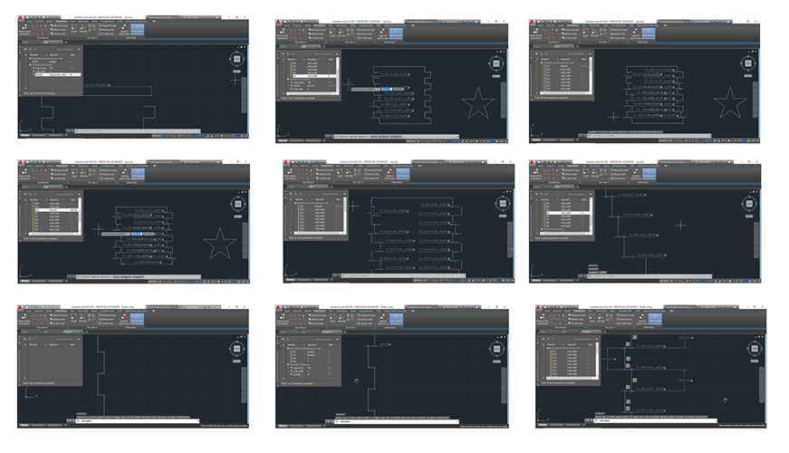
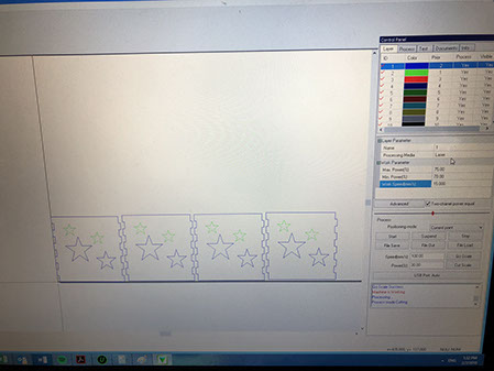
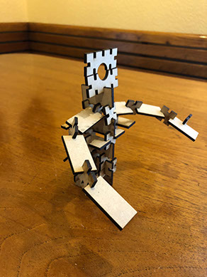
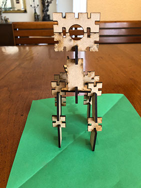
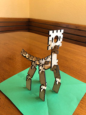
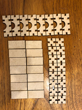
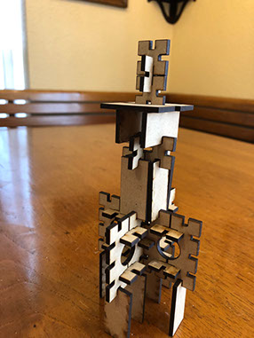
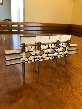
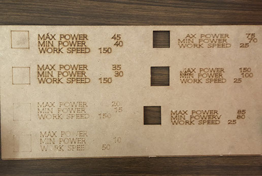
What I did: I made a press fit project, it looks something like a puzzle, the idea is to be able to build different figures while using your imagination. Below you can see a robot, a dinosaur a tower and a wall. The process to make this pieces was the same that I used to build the stars lantern. I believe the file can be bettered by changing the size of the pieces that have arcs so they will have the same measures as the rectangles ,and at the same time be the same size as the double of the squares. This way it will all fit better. To cut I used the parameters shown in the image below, I chose the Max power 75, min power is set to 70 and the work speed is 25. Below you can appreciate the different combinations to get a different result regarding cutting.
It is very important to note that all this files are parametric (you can see it in the picture below), that means that you can change the value in the ribbon to the left and the whole object will change its dimensions. The parametric tool is very useful because you can make size changes or material changes very easy. You do not have to make the hole object new, just change the values.
Click on the image
to download file
Click on the image
to download file
Click on the image
to download file
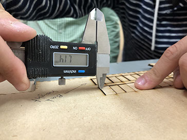
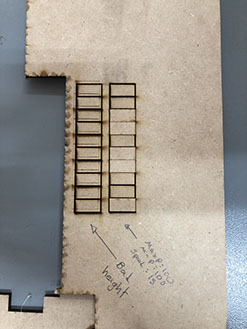
I must note that it is very important to know the width of the laser beam before cutting. To know that I had to measure the material and then we made rectangles to measure the space that was burned between each rectangle.
I realized that it was lost about 2.9 mm so the laser beam measures about 0.3 mm. For the parameters of the machine, I used 75% for max power and 70% for the min power as 23 for speed.
Right click and save as here to download .dfx file
Sadly the star box didn't fit right, it was a bit loose. That happened because the male and female parts, measured the same. I adding 0,3mm to the male part, I didn't modify the female part though, this way I got a tight union. Below you can find the corrected file with a correction in the kerf.
Click here to download .dwg file with correction
Right click and save as here to download .dfx file with correction
This pressfit did fit, but in some parts it was a bit loose, so I corrected the file to make it fit better.
Click here to download .dwg file
Right click and save as here to download .dfx file
Right click and save as here to download .igs file
Right click and save as here to download .igs file
Right click and save as here to download .igs file
Click here to download .dwg file
Click here to download .dwg file