6
3D scanning and printing
What I learned: How to print in 3D both a physical product (scanned with pictures in ReCap Photo), and one designed from scratch in AutoCad.
Sources and inspiration used:
Template used to test 3D printing: https://www.thingiverse.com/thing:1019228
Tutorial used to make the 3D print: https://www.youtube.com/watch?v=MzNJI3CY47s
Link to download Autodesk ReCap Photo: https://www.autodesk.com/products/recap/overview
Rostock MAX: https://www.3dhubs.com/3d-printers/rostock-max
DWS 3D Printer: http://www.dwssystems.com/
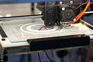
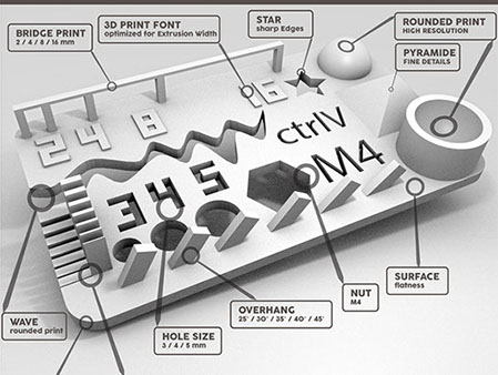
What I did: As a group assignment we chose a template with different forms to print and this way be able to test the printer and see its capabilities. The piece was tested at the time of printing to see the overhangs, closed angles, separations, and that we discovered the capabilities of the printer. An FDM printer was used.
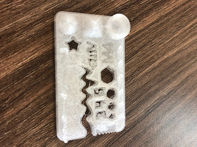
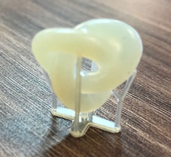
I decided to print the image below in wax because later on I would like to turn it into a pendant. I also decide to use that image because with other methods it would not be easily made. The spaces between have not enough space for the tool to enter and work. That could also damage the piece. In the test we made, ypu can see that the overhang bridge didn't have the expected resolution.
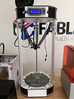
The machine used to 3D print that piece is the Rostock MAX, here are its specifications:
PRINTER TYPE FDM
MATERIAL ABS, PLA, Exotics
BUILD VOLUME 28 x 28 x 375 cm
MIN LAYER HEIGHT 20 microns
EXTRUDER HEAD 1
PRINTING SPEED 100 mm/s
OPEN SOURCE Hardware & software
CAN YOU USE 3RD PARTY MATERIAL? Yes
HEATED PLATFORM Yes
FILAMENT DIAMETER 1.75
ON-PRINTER CONTROLS Yes
CONNECTIVITY USB
Those specifications are the ones that appear in the website from the 3 printer. What they mean is that the printer can build forms from 28 x 28 x 375 cm. It works with and open source hardware and software(it means it is licensed in such a way that it can be studied, modified, created, and distributed by anyone). It also works at 100 m per second and you can use other materials other than from the firm that made the machine. The platform is heated so the piece doesn't brake while being built. The diameter of the filament is 1.75 and the printer has controls on it, so you can work easier not only relying in the computer.
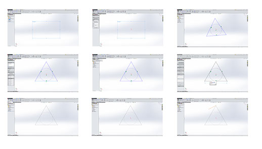
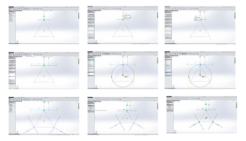
What I did: I started by choosing the top plane and Sketch. Use polygon and draw a triangle, afterwards I chose the horizontal tool and with smart dimension I changed the measure to 60 mm.
Then I selected the 3D sketch line and draw three lines. With the smart dimension I changed the length of 40 mm and selecting three lines I made them equal. Afterwards I chose the top plane and made the distance 20. With the sketch tool I draw a vertical line at the top and a horizontal one passing through the origin, making it midpoint. Once that was done I used the smart dimension tool to change the measures to 20.
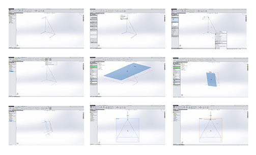
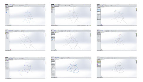
With circular sketch pattern I selected both lines from the center point and I clicked in the calculate button. In 3D Sketch with the tool centerline I connected different points while selecting two lines and making them tangent. With the spline tool I connected the points to make the infinite structure. I clicked the reference geometry and choose the plane option. I
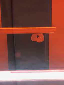
selected the 3D structure and selected the sketch with smart dimension in 40 mm. I hid the plane and chose the swept boss /base option selecting the path. I hid all the background planes and sketches and changed the color of the figure. I used a DWS digitalwax 3D printing machine.
I decided to 3D print the piece shown below because the CNC is not the correct machine to be used because of the geometry of my piece. A three axis CNC is not able to cut the piece unless I rotate the piece manually. Maybe with a fifth axis I could but the fabrication wouldn't be easy. Just above the knot the CNC tool wouldn't be able to enter and it would destroy the top of the piece.
What I did:
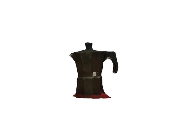
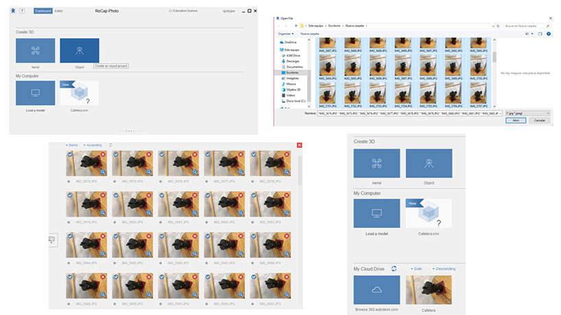
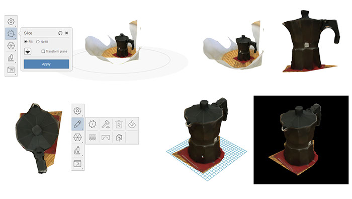
To make the scan in 3D, I chose a figure to scan, in this case it was a coffee machine. First I downloaded Autodesk ReCap Photo, once installed I took pictures around the coffee machine. I uploaded these photos in the software, I waited a few minutes and the model was ready. I edited it a bit to remove the unnecessary parts and exported it as an image. I decided to use the software stated, because it is easy to use, you just have to take multiple pictures around something and its done. Built I must say it didn't end up quite the way I expected it, I thought it would be cleaner. An other option to 3d scan is to use other app or an actual 3D scanner.
I used photogrammetry, that means I took several photos of the same thing from different angles. And that way I built up the image. However, the reconstruction might not be the best, because sometimes there are no visual patterns to detect.
On the other hand I could have used a 3d scanner, those are more expensive. They use infrared light projection to construct geometrically, no special light setup is needed, opposed to photogrammetry. I used my phone to scan, it was a lot of fun but I had to give it a couple tries before I got the final image nd that was a huge disadvantage . That is because I couldn't just go around the coffee pot, I had to have some sort of angle so I could photograph the sides as well as the top. I couldn't upload all the images I wanted because the software has a limited amount of images it accepts, I couldn't upload more than 145. On the other hand, the mothod I used (scanning by taking pictures with my phone) had the advantage that it was really easy to do and also cheap, the software didn't cost a thing and I already had the phone).
Sadly as you can see, my scan wasn't perfect, it had rough edges, and it looked a bit weird, but I love that I could scan it, my guess is that with professional equipment I could have a perfect coffee machine.
Click on the image
to download file
Click on the image
to download .dwg file
Click on the image
to download file
This image shows the test file follow this link:
https://www.thingiverse.com/thing:1019228
Right click here
to download .stl file
.jpg?crc=233040945)
.jpg?crc=4182569928)

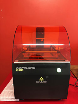
3D Printing Method: Laser Stereolithography
Working Area: Ø 180x180 mm
Laser Source: Solid State BluEdge® BE-1300X
Slice Thickness* 10-100 microns
Scanning Method: Galvanometer
Software: Fictor® XFAB Edition, Nauta® XFAB Edition
Input File Format: .stl, .slc, .nauta, .fictor, .mkr, .3dm,
.3ds, .ply, .obj, .lwo, .x
Machine Size: 400x606x642 mm
Operating Temperature and Humidity: 20°-25°C / 60%
Power Supply: 24V DC with AC 240/100V / 50-60 Hz external supplier included
Operating System: Windows7 or higher
Memory: 2 Gbyte
Graphics Card: compatible with OpenGL
I/O Interfaces: 1 USB port
Connectivity: 1 active internet connection
Recommended Configuration: Dual Core Processor or above, memory 4 GB
Cylindrical work area: ø 180 mm.
Compact design for desktop use.
Printer with “Plug and Play” USB connection.
Simple and intuitive interface.
Patented work platform with instruments for easy removal of models.
TTT (Tank Translation Technology) patented system, which optimises the tank consumption, increasing its duration.
Automatic heating system and material temperature control.
BluEdge® proprietary laser.
No calibration required.
Proprietary 3D editor: NAUTA® XFAB Edition with automatic generation of support structures.
Parametric technology.
Simplified support removal, with no risk of model damage.
Wide range of importable 3D formats.
Fictor® XFAB Edition printer management software
Main Features and specs from FAB 2500SD DWS 3D printer