7

Electronics design
What I learned: I redraw a board, adding a button to turn a LED on and off.
Sources and inspiration used:
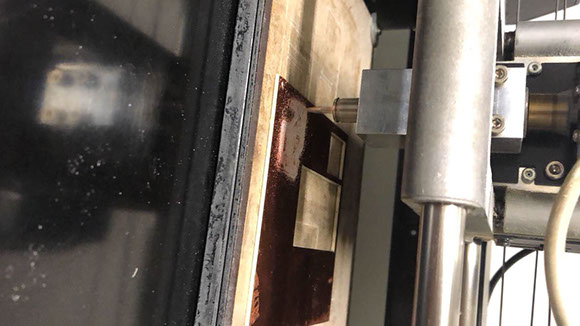
What I did: First as a group we tested the equipment to observe the operation of a microcontroller circuit board. What this board will do turn on and off a light while pushing a button.
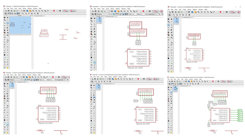
I'm still a newbie designing, so I decided to build a simple circuit, with big routes (so it would be easier for me to weld. I looked on the Internet what each pin made for the Atiny45, so I could connect it to either the Led or the button. Once I managed to connect everything, I started to make the routes, it was difficult at the beginning because I had to be able to make paths that didn't overlap, and that was quite a task for me.
Then downloaded EAGLE, a PCB Design and Schematic Software from Autodesk. I chose to use Eagle from Autodesk to design because it is very visual and somewhat easy-to-use PCB design and schematic software. After that I used Neil's Hellow Board as inspiration.
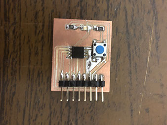
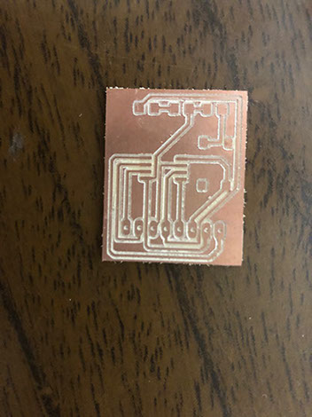
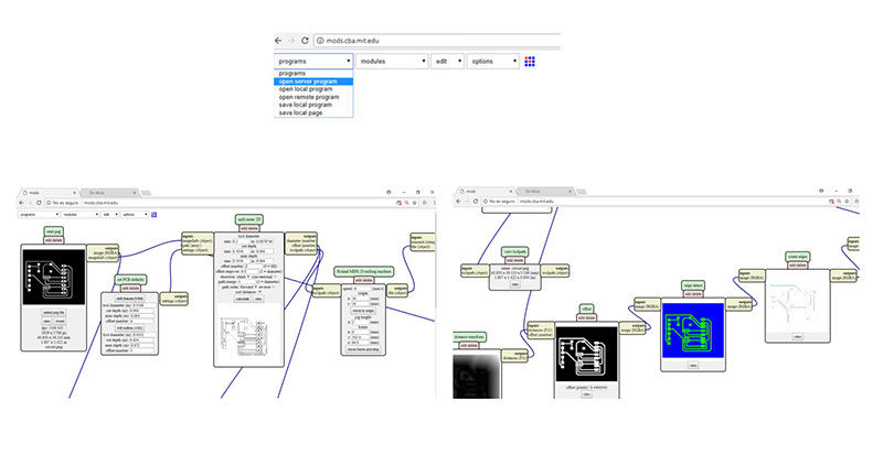
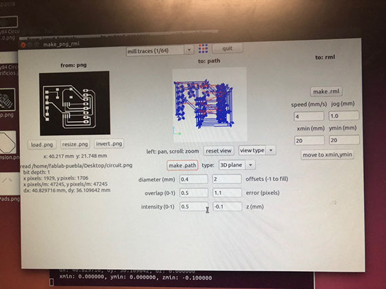
This circuit has a TINY45-20-SMT, (is the micro-controller) Pinhead 1x08 (to connect it to power and also to connect it to the programmer so I can later on program it), two Resistors R1206, tact and a LED_1206 (to turn it on and off). I tried to use mods.cba.mit.edu to cut the circuit, but mostly with the drivers, so I had I used the milling machine. A tact is a button, so when pressed it sends information to the program to do different things, like to turn on a Led.
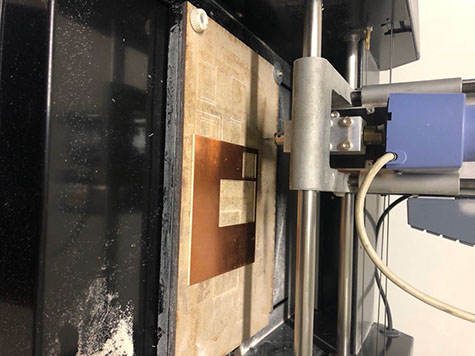
I also had trouble trying to cut the circuit, it wasn't well attached and it moved. When I tried to program the circuit I realized that the design was not the best, therefore I couldn't program it. But later on I was able to reflow the solder and program it. Sadly I didn't take any picture of that.
I used an internal oscillator, that's why I didn't use a crustal. I tried to use a Fab Modul, but I had trouble with the drivers and thats why I had to use the old version. I also calculated the resistance for my LED with the formula V=ri. In the data sheet I cheeked that the maximum current is 100 ma, and because I don't like working with the maximum of energy I calculated that a resistance of 100 could work with 50 ma because it has 5V, working to half it's capacity.
On the other side, the button has a high resistance in pull down mode, so when it is pressed the button read a HIGH.
Click on the image
to download file
Click on the image
to download file
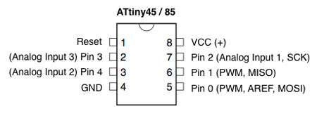
Here you can visualize the Atiny Pinout
The resistors needed have a value of 220 ohms and 10 ohms (the number written on each is 2200 and 1002). The resistor above the takt has the value of 1002

Click on each image
to download .png file
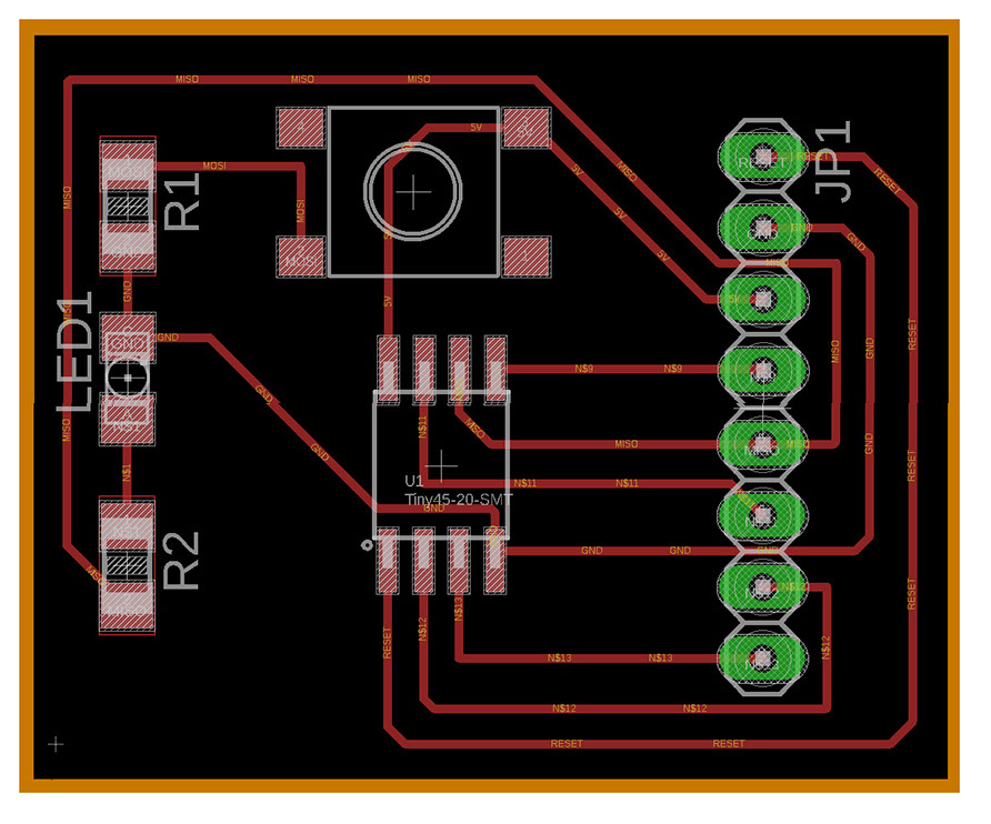
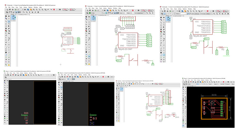
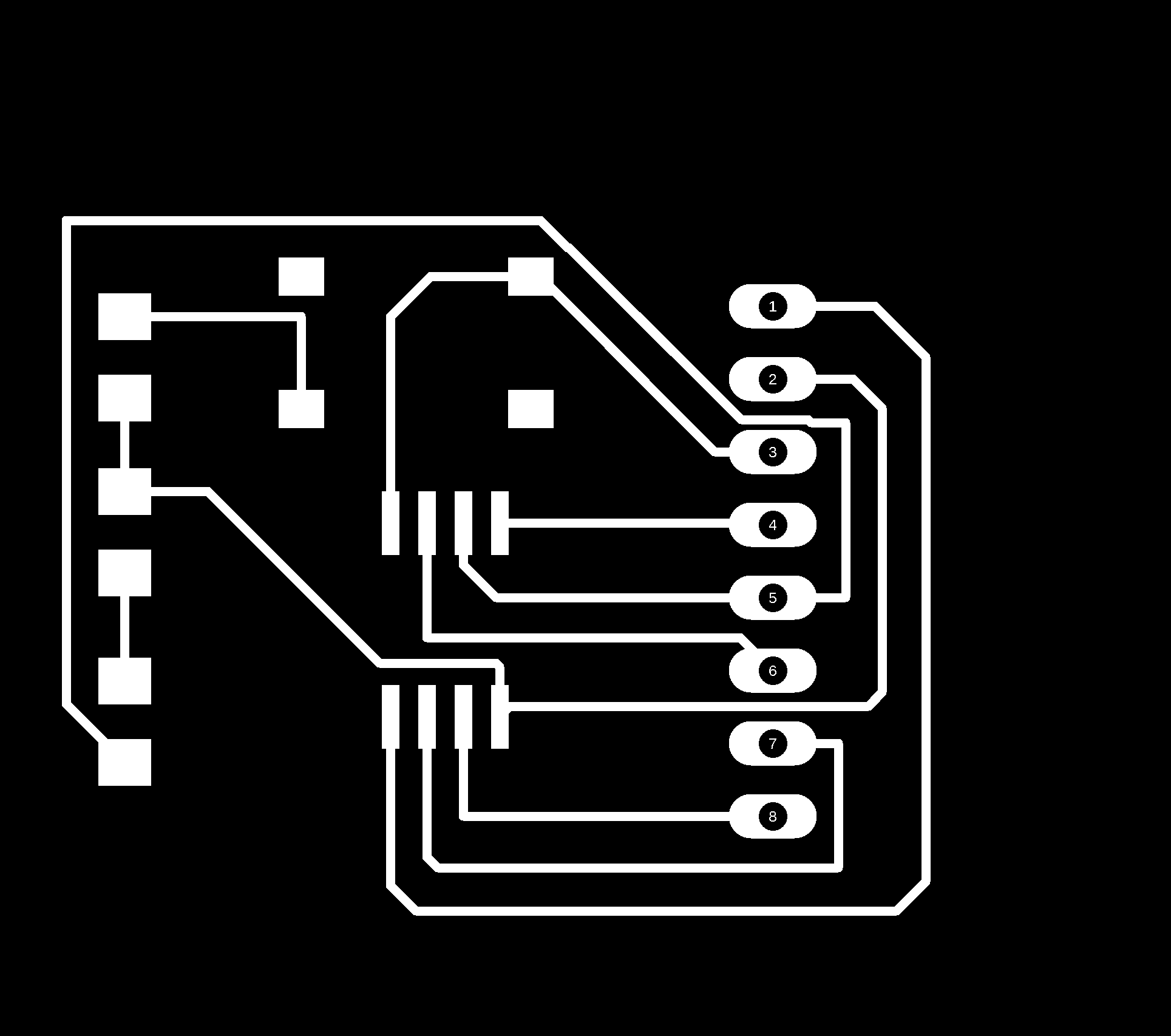
This picture shows the traces and which component goes in which place
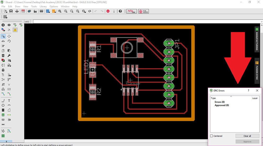
This picture shows if there are DRC errors (you can find that tool at the bottom of the left side menu)