Team Work
Mechanical and Machine design
What we learned:
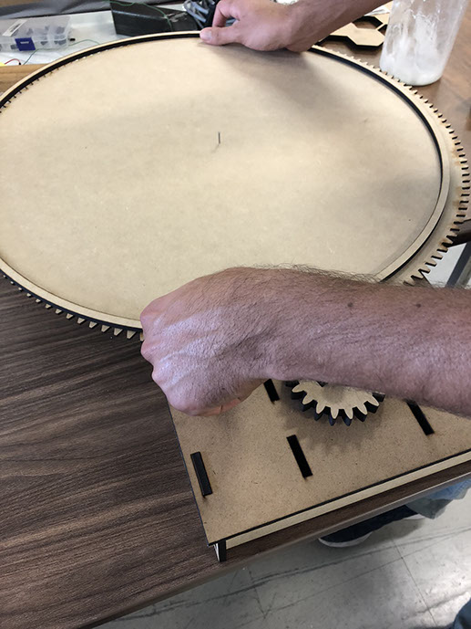
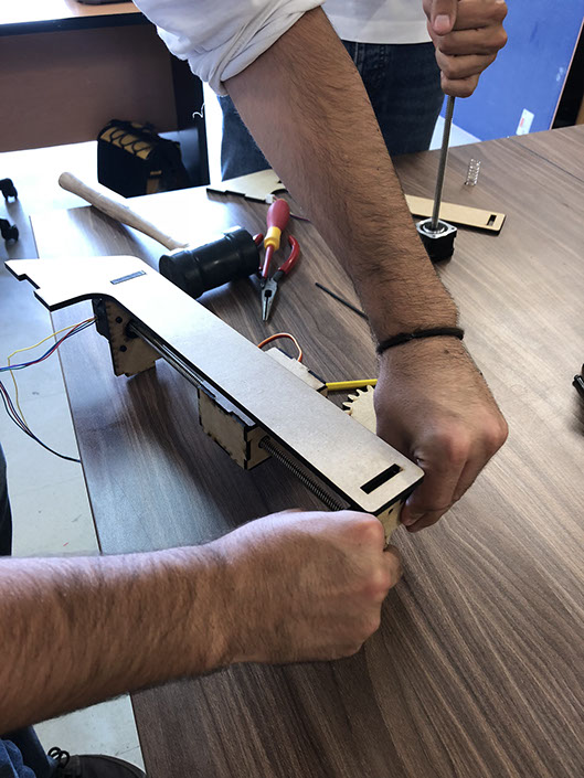
As a group we designed a machine that includes a mechanism, actuation and automation. We built the mechanical parts and made sure it operated manually. Later we actuated and automated the machine.
Sources and inspiration used:
Sand spining art https://www.youtube.com/watch?v=pH4X8TwVmzI
Mathieu Laporte: http://archive.fabacademy.org/2017/echofab/students/99/week11.html
Gaurang Shetty: http://archive.fabacademy.org/2017/fablabriidl/students/377/assignment111.html
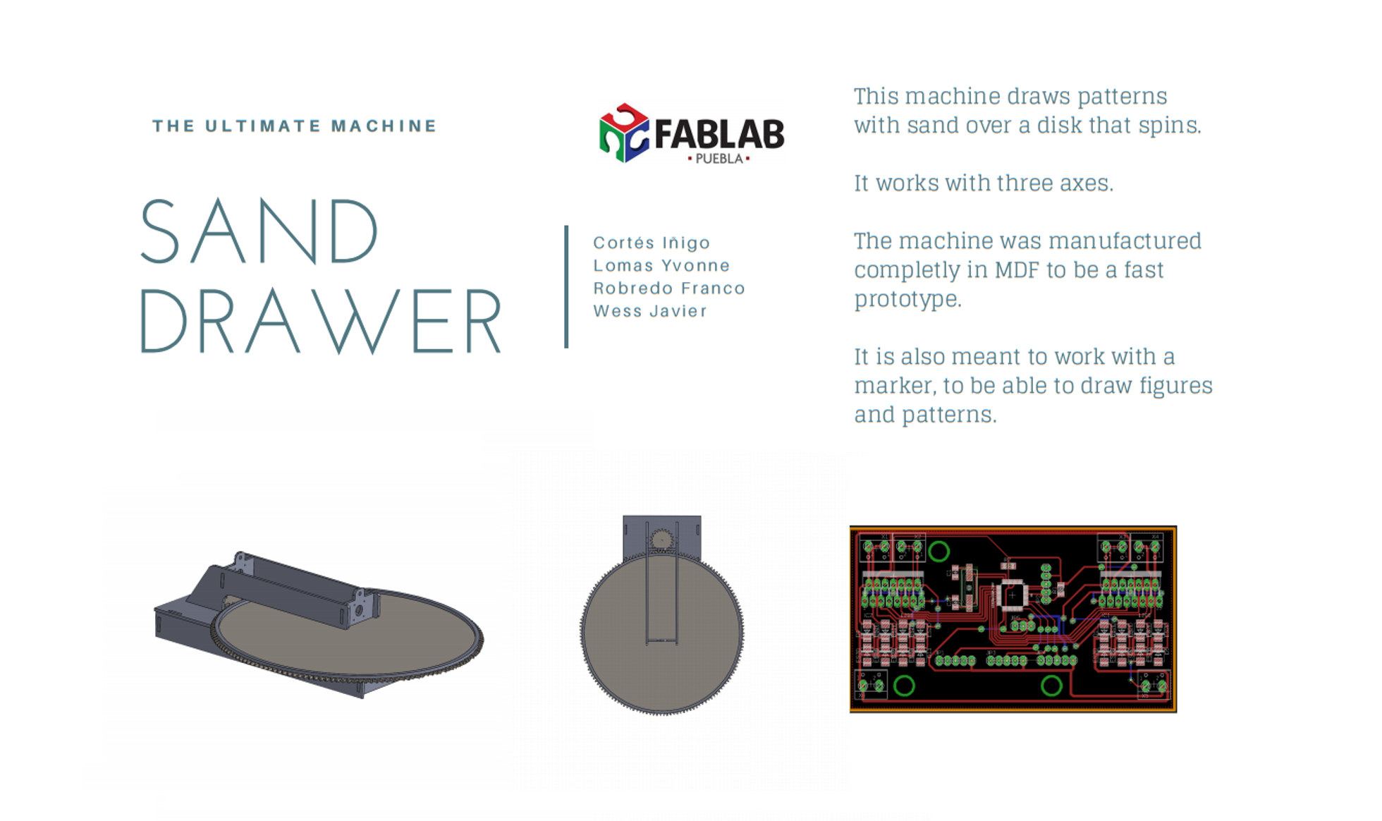
What we did: First, we decided which kind of machine we were going to build. We chose to make a machine that draws patterns with sand over a disk that spins. Below you can see where we took inspiration from.
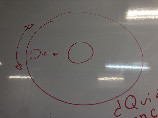
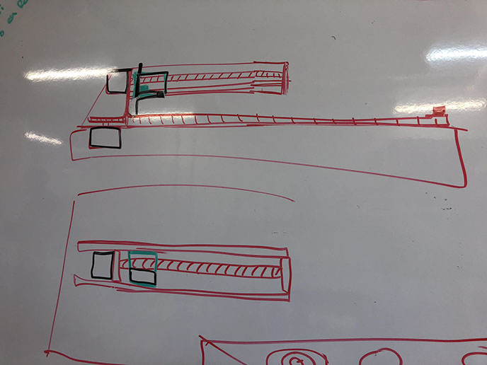
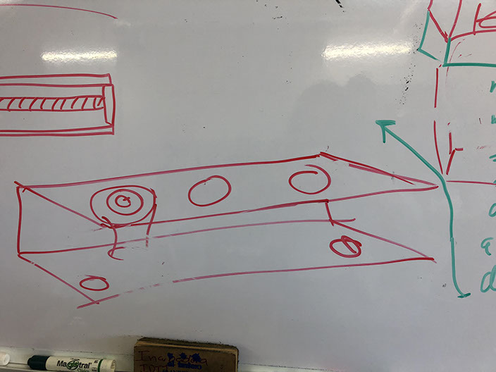
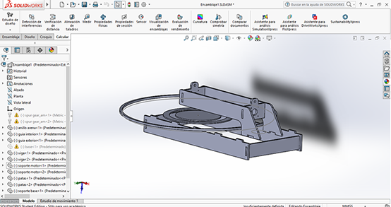
Then we started to brainstorm and sketch the ideas for the machine. Below you can see the sketches we made. The main idea is to build the disk and the structure, then with a code we can instruct the machine to draw the patterns.
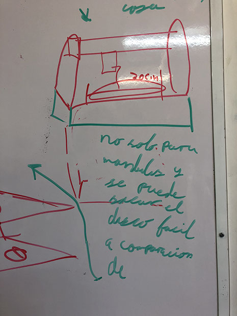
The CNC machine that we created is for drawing on sand or engraving with a marker. We were inspired by the project of Guarang Shetty which is an XY plotter that can draw on a paper. We are also inspired by the project of Mathieu Laporte, his machine has X and Y axes, it is meant to draw in the sand using a metal ball and a magnet on top of one of the axe. It'll use G-code to make simple shapes on the sand.
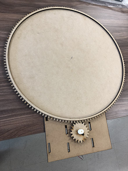
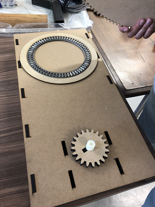
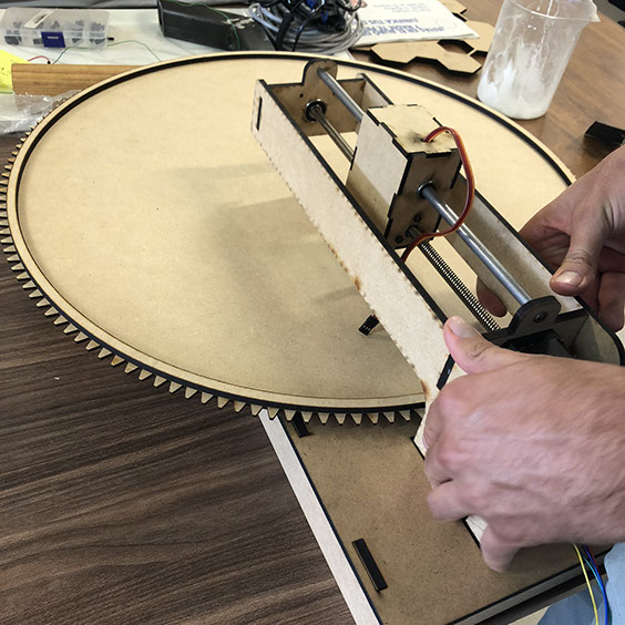
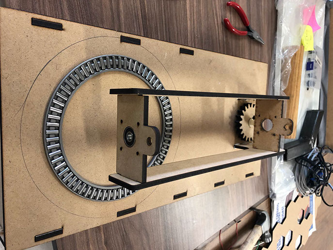
We seek to develop a similar but simpler machine that meets the expectations of working with three axes. The machine was manufactured in MDF to be a fast prototype.
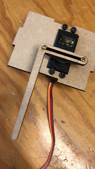
We got the metal bearing for the project and we used the engines that our guru gave us.
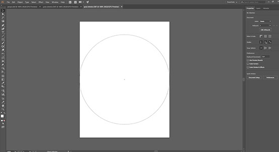
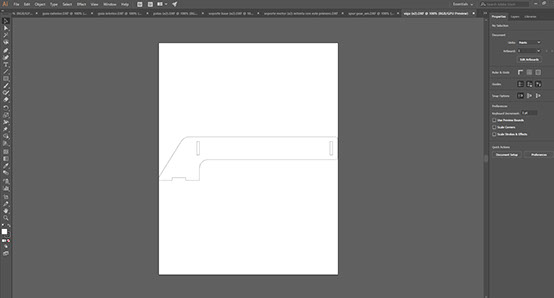
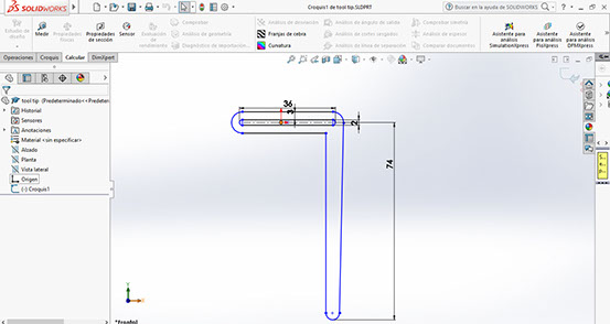
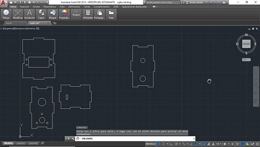
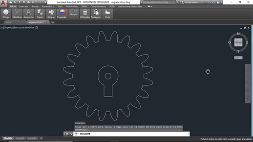
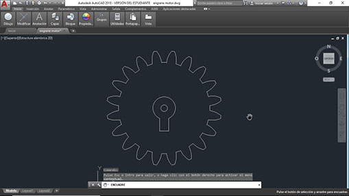
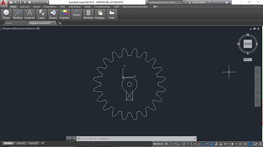
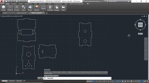
Below you cans see the the Solidworks files in SolidWroks format and also in DFX
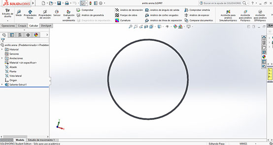
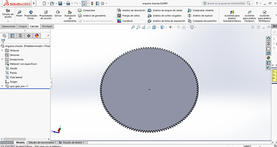
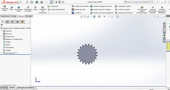
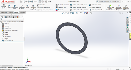
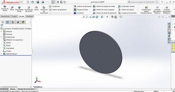
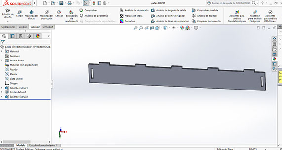
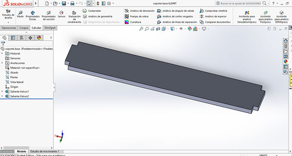
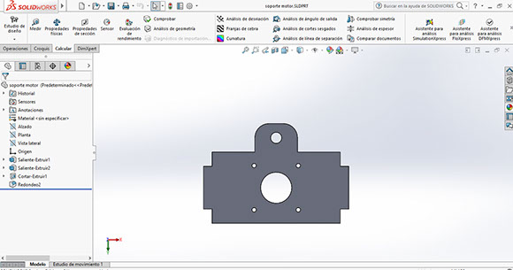
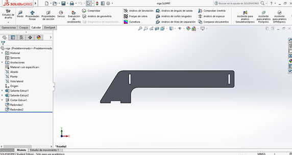
Click on each image
to download Solidworks and AutoCad file
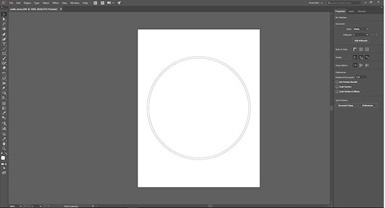
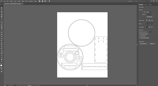
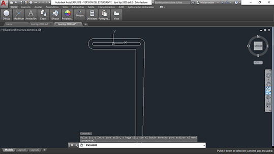
Click on each image
to download DFX file


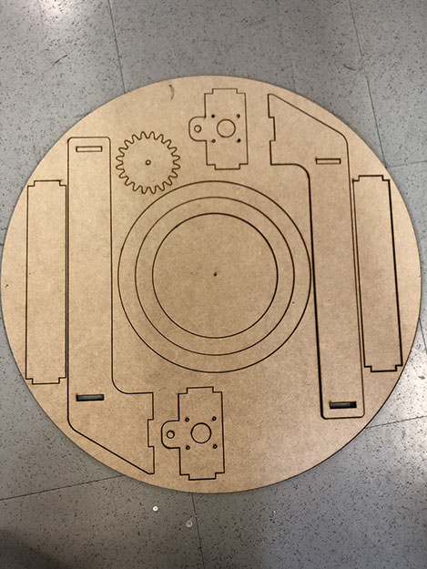
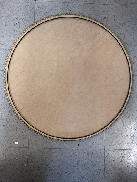
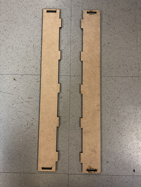
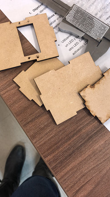
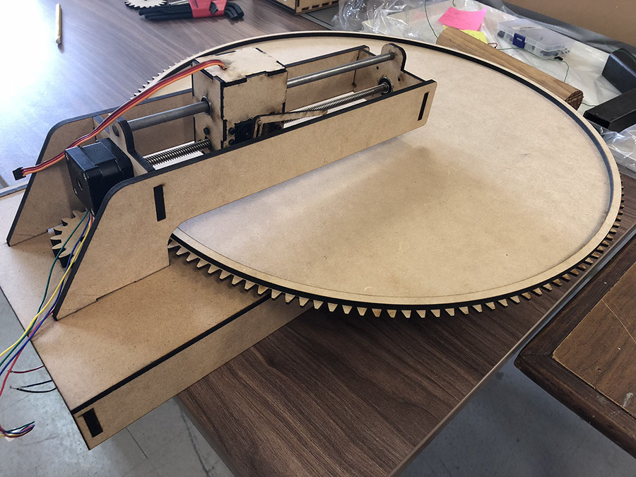
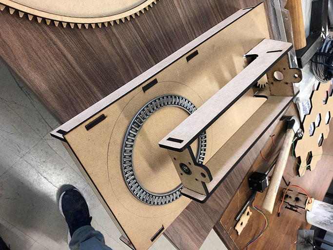
Below you cans see the MDF pieces cut with laser

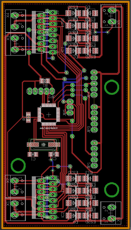
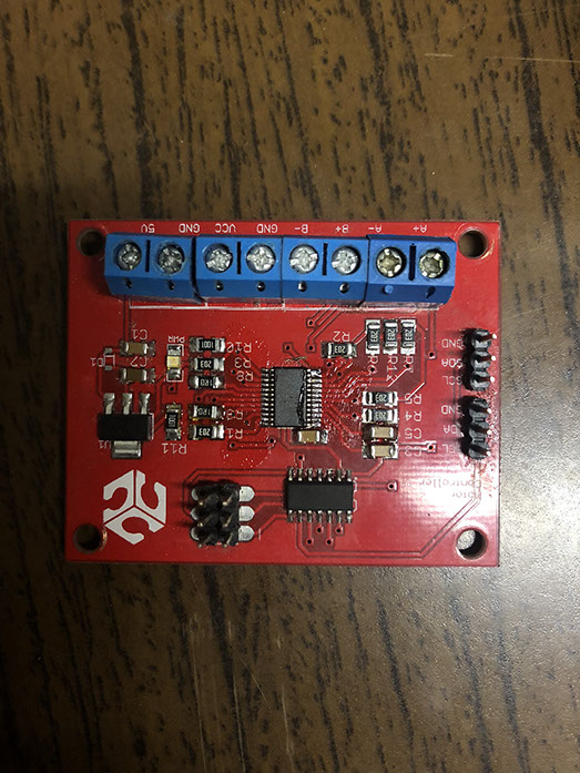
Below you can find the BRD and SCH files used for the machine. The components used are: Atmega328, two multiwatt 15 lead (L298), a crystal, diodes, resistors, pinheads, capacitors, clamps.
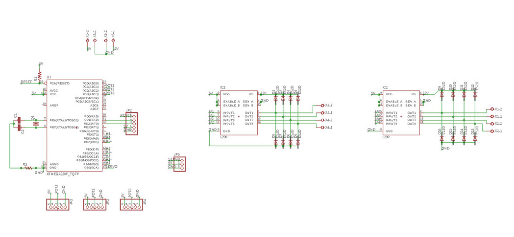
Click on the image
to download file
Click on the image
to download file
We needed two programs to run the machine, the first one to move the disk with a constant movement. The second program is to create the drawings. The programs were made in Arduino, below you can find the files.
Click on the poster to download file
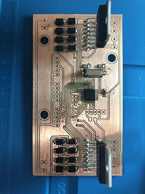
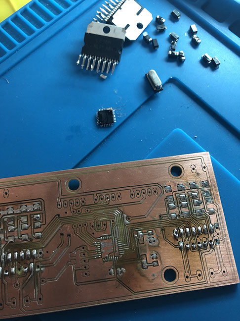
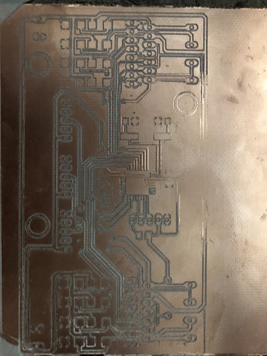
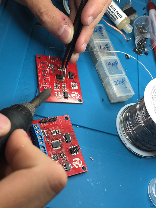
It is important to note that to make the first circuit pictured in this site, we had to consider the second one. So that all the pins fit in the write way. We started welding the components to the new circuit, but we realized that there was a mistake in the routes, due to the material the routs didn't work. So we had to un-weld everything and cut again the circuit, below you can see the process.
We then decided to use an Inhous eFab Modus live circuite, made in Puebla. Due to technical complications. You can find the circuit below.
We cut in laser a sheet of paper where we could make a drawing.
In the video below you can see us testing the machine. These tests consist of testing from the serial monitor. A number is pressed and then the motor moves. If you press another number, it stops. Everything happens from the computer, direct in interface, for that reason we do not use a button.
It worked
Click on the image
to download file
Click on the image
to download file
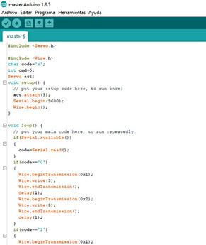
This is the master program
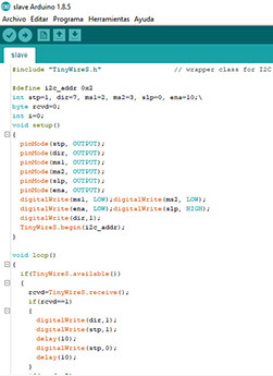
This is the slave program
#include <Servo.h>
#include <Wire.h>
char code='x';
int cmd=0;
Servo act;
void setup() {
// put your setup code here, to run once:
act.attach(9);
Serial.begin(9600);
Wire.begin();
}
void loop() {
// put your main code here, to run repeatedly:
if(Serial.available())
{
code=Serial.read();
}
if(code=='0')
{
Wire.beginTransmission(0x1);
Wire.write(3);
Wire.endTransmission();
delay(1);
Wire.beginTransmission(0x2);
Wire.write(3);
Wire.endTransmission();
delay(1);
}
if(code=='1')
{
Wire.beginTransmission(0x1);
Wire.write(1);
Wire.endTransmission();
delay(1);
}
if(code=='2')
{
Wire.beginTransmission(0x1);
Wire.write(2);
Wire.endTransmission();
delay(1);
}
if(code=='3')
{
Wire.beginTransmission(0x2);
Wire.write(1);
Wire.endTransmission();
delay(1);
}
if(code=='4')
{
Wire.beginTransmission(0x2);
Wire.write(2);
Wire.endTransmission();
delay(1);
}
if(code=='5')
{
act.write(45);
}
if(code=='6')
{
act.write(55);
}
}
#include "TinyWireS.h" // wrapper class for I2C slave routines
#define i2c_addr 0x2
int stp=1, dir=7, ms1=2, ms2=3, slp=0, ena=10;\
byte rcvd=0;
int i=0;
void setup()
{
pinMode(stp, OUTPUT);
pinMode(dir, OUTPUT);
pinMode(ms1, OUTPUT);
pinMode(ms2, OUTPUT);
pinMode(slp, OUTPUT);
pinMode(ena, OUTPUT);
digitalWrite(ms1, LOW);digitalWrite(ms2, LOW);
digitalWrite(ena, LOW);digitalWrite(slp, HIGH);
digitalWrite(dir,1);
TinyWireS.begin(i2c_addr);
}
void loop()
{
if(TinyWireS.available())
{
rcvd=TinyWireS.receive();
if(rcvd==1)
{
digitalWrite(dir,1);
digitalWrite(stp,1);
delay(10);
digitalWrite(stp,0);
delay(10);
}
if(rcvd==2)
{
digitalWrite(dir,0);
digitalWrite(stp,1);
delay(10);
digitalWrite(stp,0);
delay(10);
}
if(rcvd==3)
{
digitalWrite(dir,1);
for(i=0; i++; i<200)
{
digitalWrite(stp,1);
delay(10);
digitalWrite(stp,0);
delay(10);
digitalWrite(stp,1);
delay(10);
}
}
if(rcvd==4)
{
digitalWrite(dir,0);
for(i=0; i++; i<200)
{
digitalWrite(stp,1);
delay(10);
digitalWrite(stp,0);
delay(10);
digitalWrite(stp,1);
delay(10);
}
}
}
}
We could better this machine by writing a more complex code so we can draw more shapes other than circles. We could also cut the machine in another material, a more solid one like steel. On the other hand we would like to try this machine using sand.
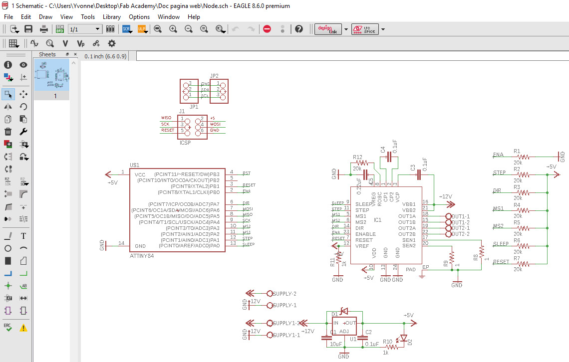
We used a local Fabhouse circuit, the design is from Fablab Puebla where I designed it but it was sent to Ryspee to be manufactured.
Characteristics of the FabHouse circuit:
Base material FR-4TG130
in two layers
PCB dimensions Width: 1.6 mm
red soldermask with white legends
Hasl finish
2 ounces of copper
6000 spaced
Minimum drill of 24000
microcontroller A4982
45x56 mm
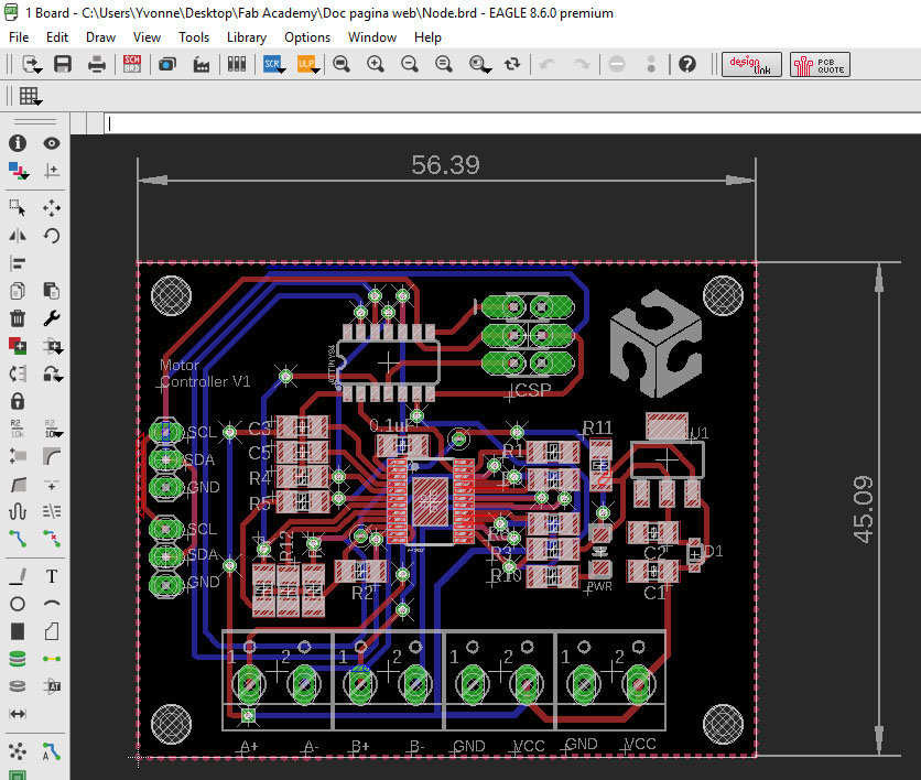
Click on the image
to download file
Click on the image
to download file
The components are: pins, ATiny84, resistors, capacitors, screw terminals,TSSOP-24, IC1; 2 L298
2 16 pinhead , 2 4 pinhead , 18 Resistor, 10 con-wago-500 , 1 Led, 3 Tact, 10 SMA-DO214AC
A possible improvement for the future is to build the machine in steel and use the water cutter machine (I would also love to learn how to use it). Maybe the design can be a bit changed so it is not that big (it's hard to find a spot to place the machine), it could be more portable.
The components are:
12 con-wago-508
1 ATmega328
2 Resistor
1 Crystal
2 Spiceprefix
4 5 pinhead
1 3 pinhead
2 L298
16 ES2D
The components are: