The concept
When I was eating my soggy breakfast cereal, a thought came to my mind. How can I enjoy my breakfast and take my time eating without being left with soggy serial. My idea was to make a device that you can put on any metal spoon that would add milk to each spoonful of cereal. To avoid sogginess the bowl of cereal would not contain any milk. With a press of a certain motion the device dispenses milk into your spoon so the cereal doesn't get soggy and you save cereal if you get stuffed. I remembered seeing a
video
from
William Osman
where he created a anti soggy cereal spoon. I wanted to develope his idea further so it was more of a commercial product, smaller in the hand (than osmans).
Then I sketched up how the idea was going to be layed out.
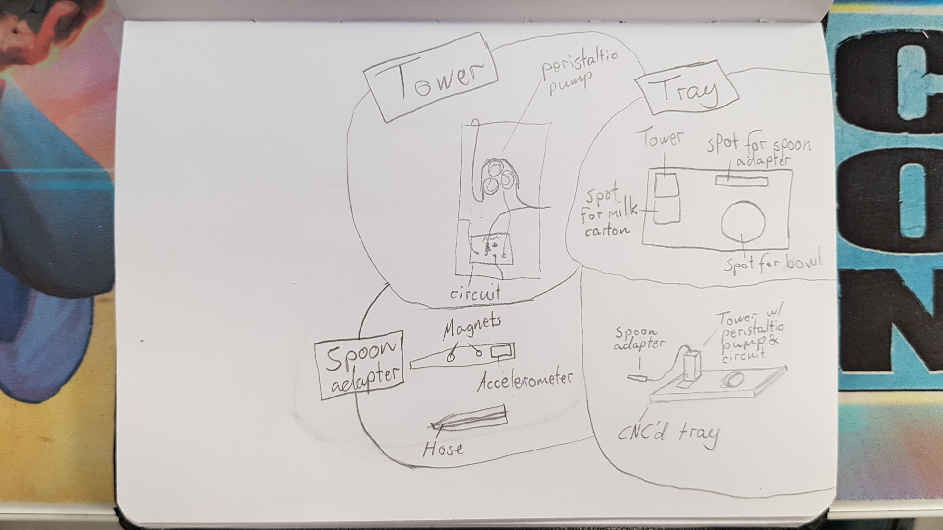
The Holder
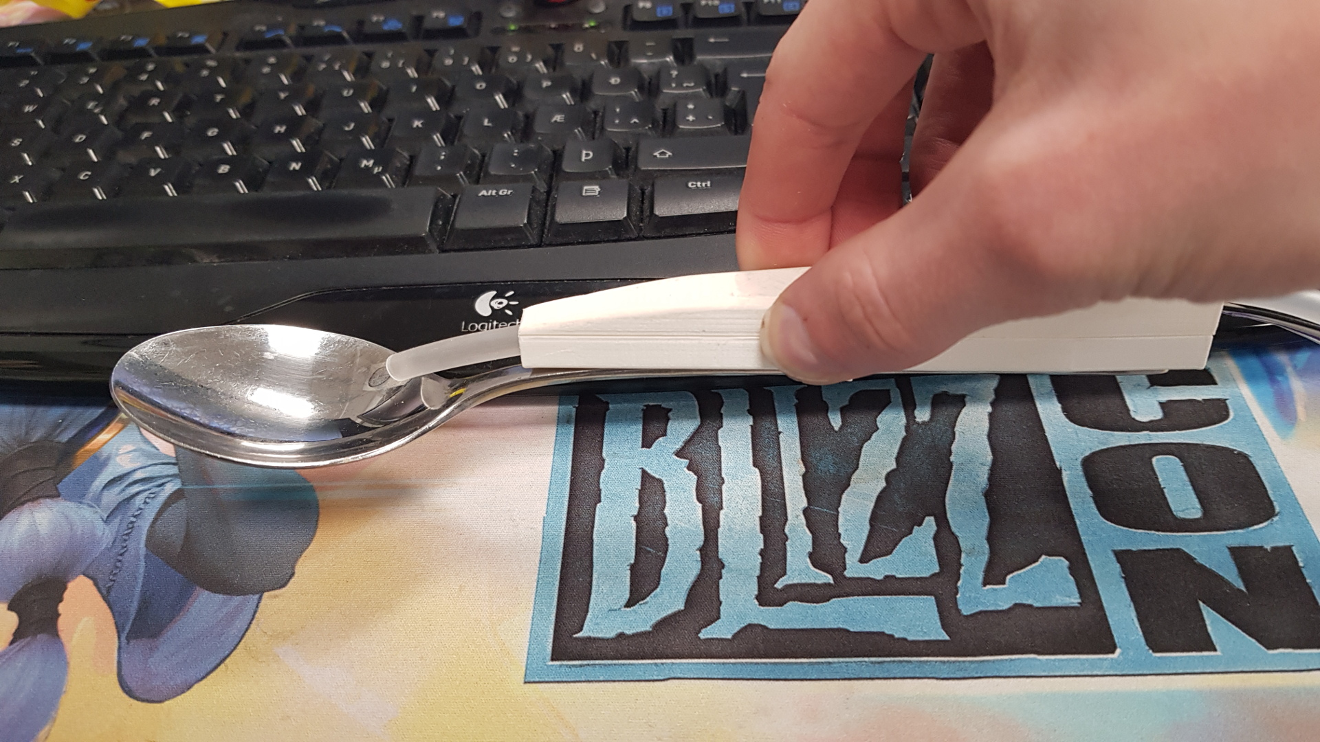
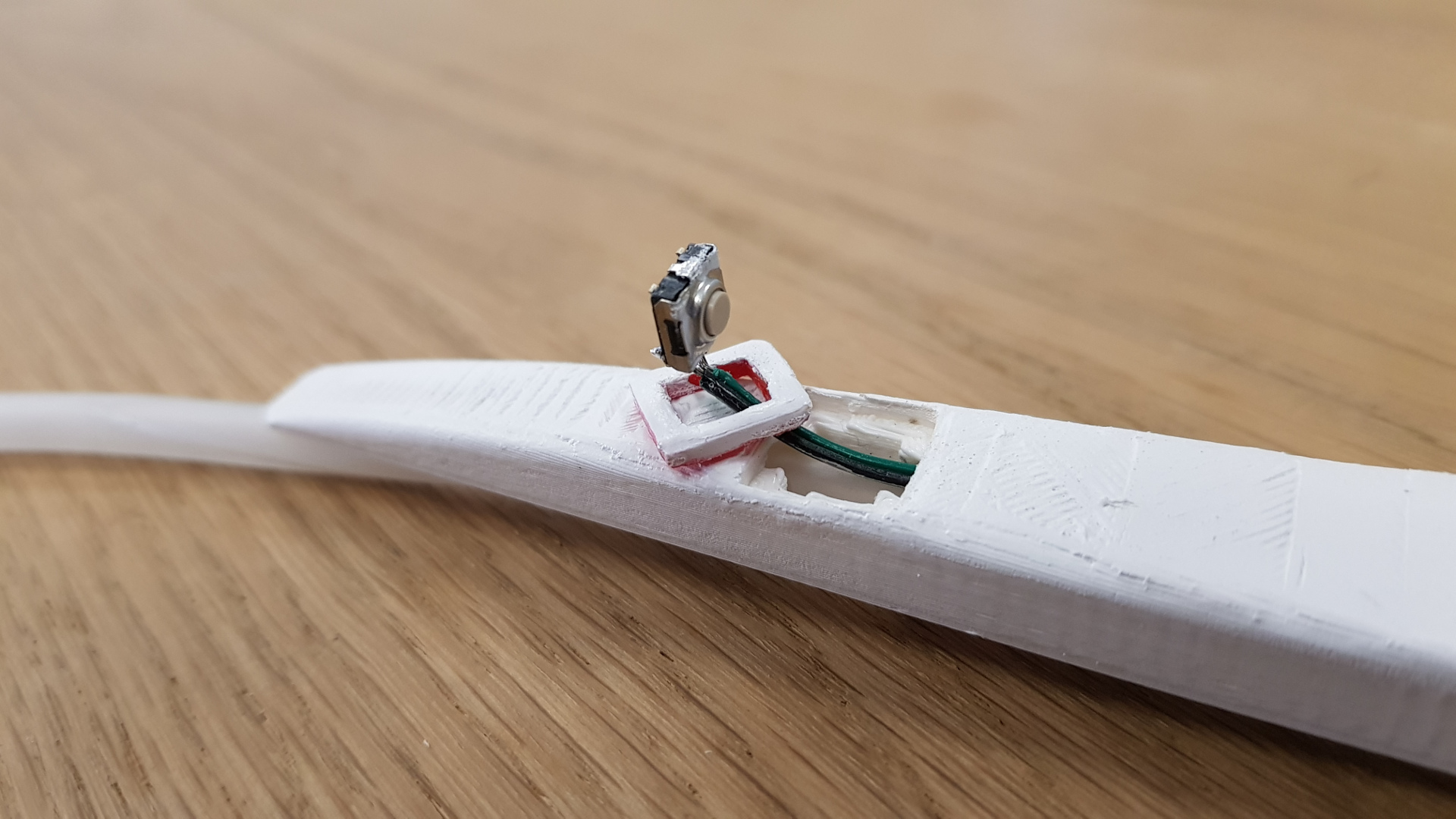
When the user is holding the spoon with the holder and makes a dipping motion, returns with the spoon flat, the pump will engage and dispense milk into the spoon. I designed it to fit nicely in the hand. To have it safe for food I added magnets so the user can use a metal spoon so it can be changed. The holder was 3d printed.
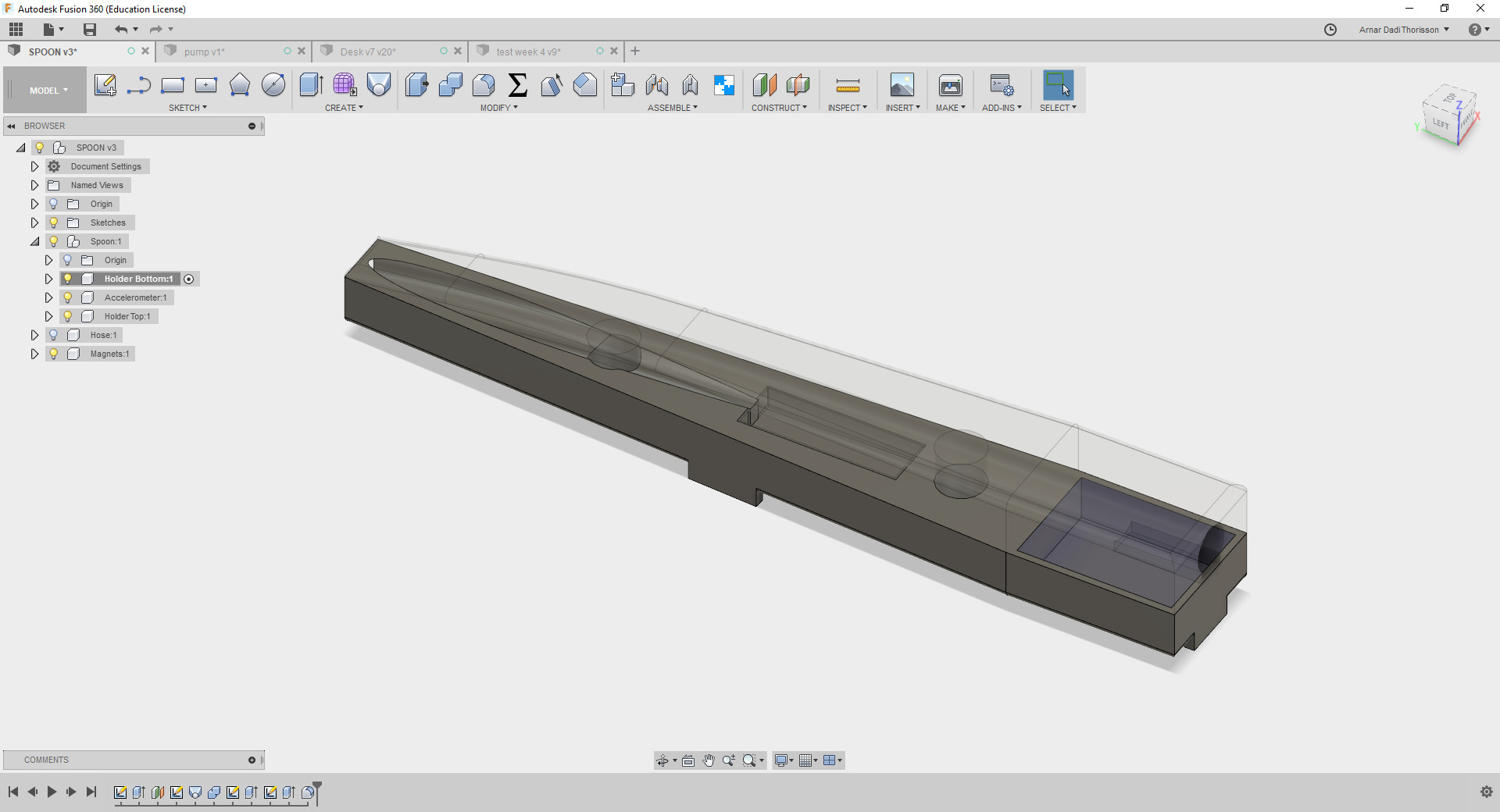
 I designed the spoon holder in fusion. I had to print it couple of times since the printer over extrudes a little so I added 0.3mm to every design that is supposed to be a tight fit so no glue or extra parts were needed.
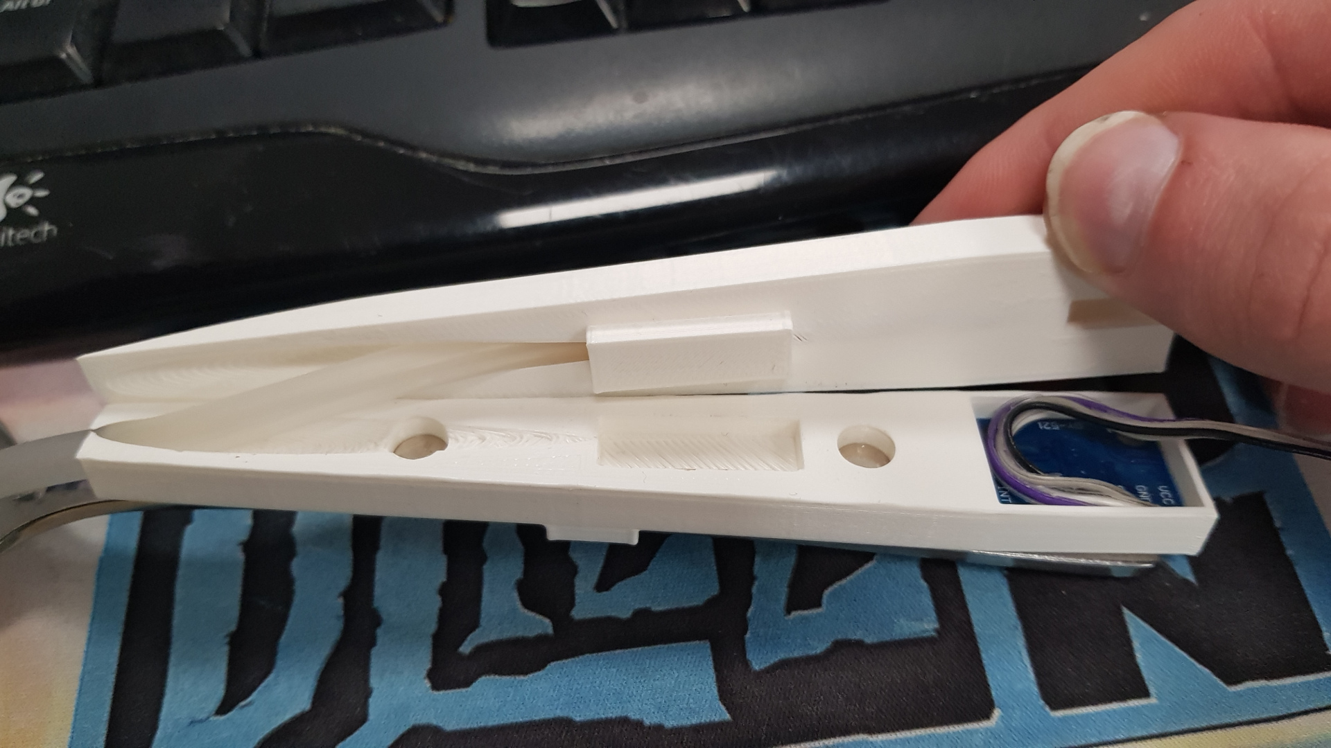 Later on I added a button.
 (þjappa myndum)
The Peristaltic Pump
The pump feeds the milk from the milk container, through the silicone tube into the spoon. Pumps similar to these are rather expensive and are used in the medical field to pump a precise amount of nutrition straight into the patient's stomach. When the pump rotates it presses the tube creating a vaccum and causing it to suck the liquid through the tube.
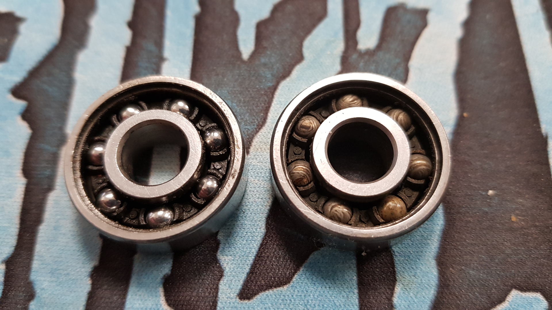
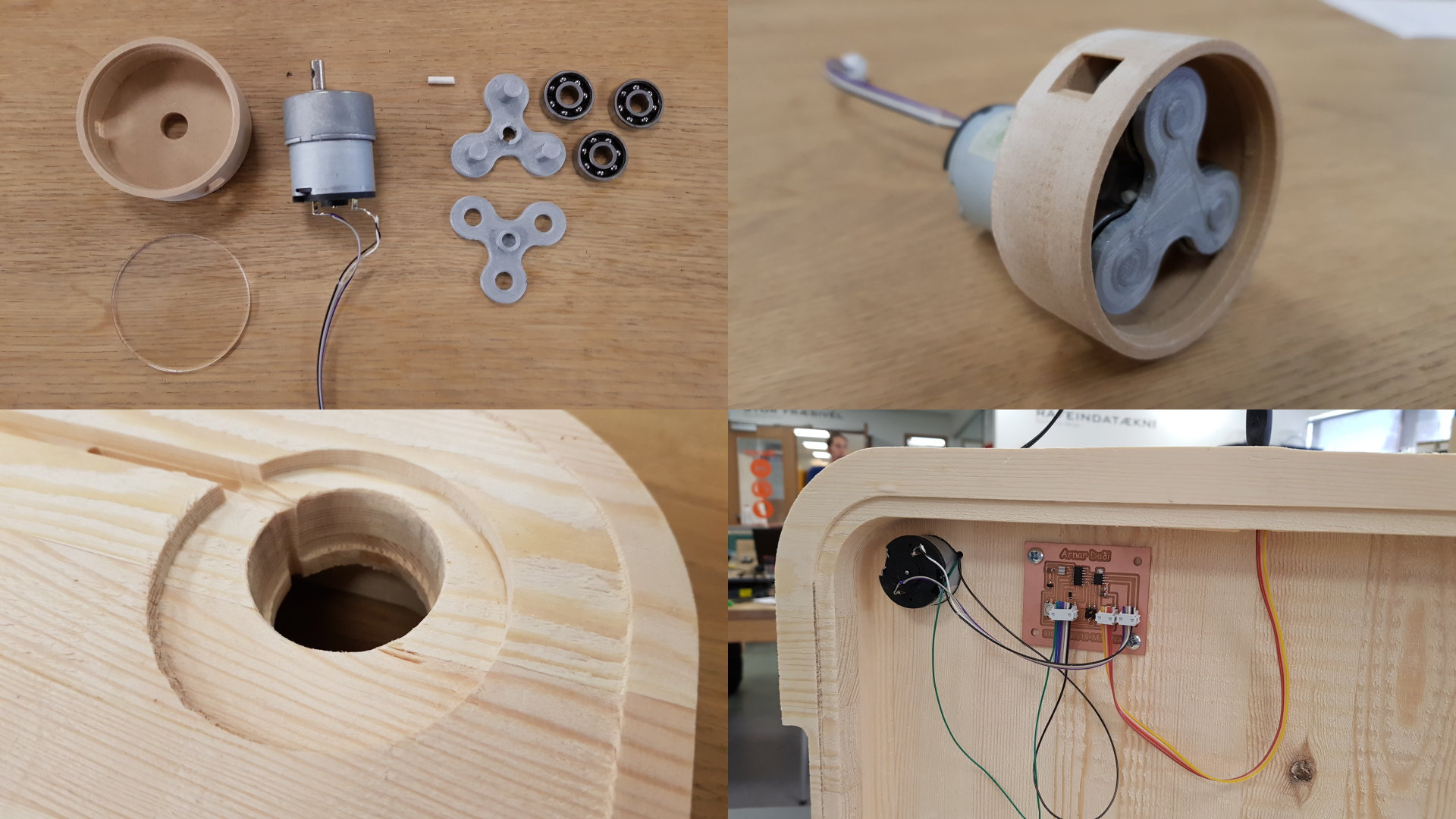
 In William Osman's video, he has a peristaltic pump controlling the flow of the milk. I decided to make my own variation of this but with a DC motor and skateboard bearings that I found laying around at my home. I will design a 3d printed casing and holder for the bearings.
All my designs are based on a core which is a triangle and each bearing is placed in the corners. Everything is around these 3 corners, which are anchored to just 1 corner.
In William Osman's video, he has a peristaltic pump controlling the flow of the milk. I decided to make my own variation of this but with a DC motor and skateboard bearings that I found laying around at my home. I will design a 3d printed casing and holder for the bearings.
All my designs are based on a core which is a triangle and each bearing is placed in the corners. Everything is around these 3 corners, which are anchored to just 1 corner.
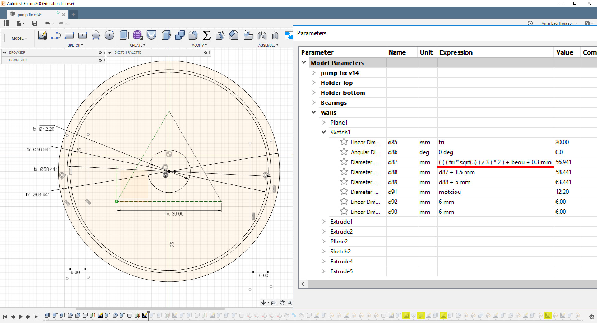
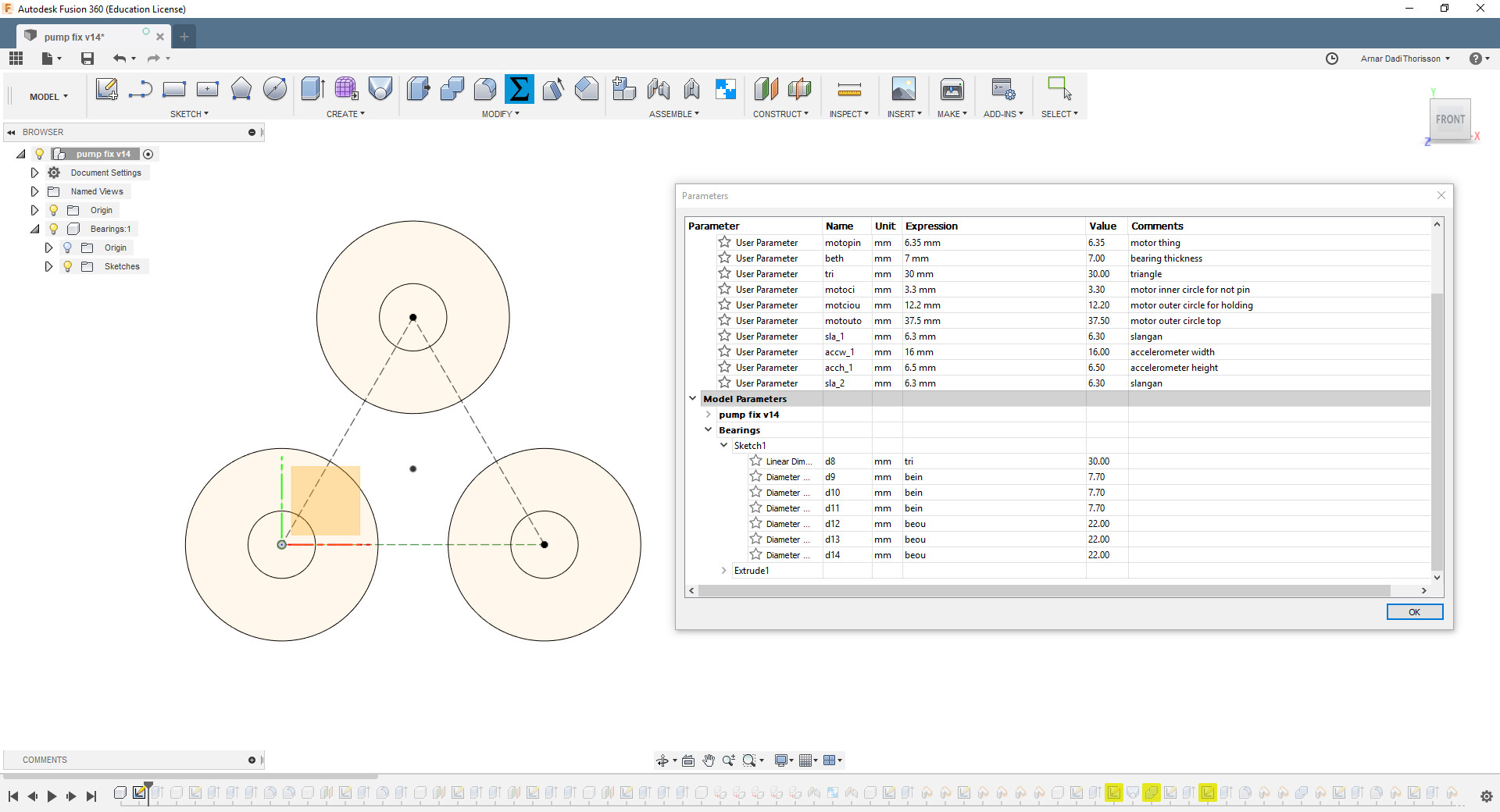 The holder (around the bearings) is built up out of a straight circle with extrusions of one triangle and fillets. There were a few remakes that I had to go through to get the parametric settings behaving correctly. I really wanted the casing and the bearings design to be parametric, in case I would end up with a different size of bearings or wanted to resize the whole design. My solution was in
this math eqation to find the equilateral triangle.
It works through putting the length of the triangle in the equation to get the equilateral triangle diameter. I gave the inner wall of the casing some space so the tube would fit in between.
The holder (around the bearings) is built up out of a straight circle with extrusions of one triangle and fillets. There were a few remakes that I had to go through to get the parametric settings behaving correctly. I really wanted the casing and the bearings design to be parametric, in case I would end up with a different size of bearings or wanted to resize the whole design. My solution was in
this math eqation to find the equilateral triangle.
It works through putting the length of the triangle in the equation to get the equilateral triangle diameter. I gave the inner wall of the casing some space so the tube would fit in between.
 The bearings were really old and dirty but I managed to salvage 3 of them by cleaning and re-greasing them.
 Explain 3d print process
The tray
rephrase beginning
To present the prototype, hide the circutboard and place the motor in something. I decided on designing a wooden tray. I found some scrap pieces of wood in the FabLab and with the assistance of the local high school wood teacher, the scraps got plained and glued together for me, so I could start shopbotting with a nice thick block of wood.
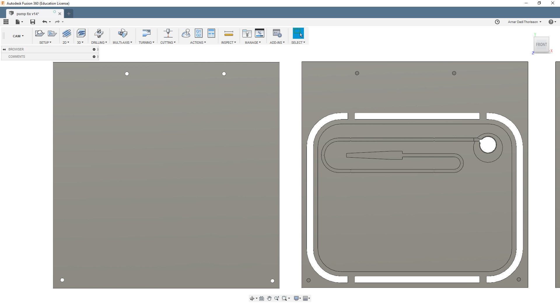
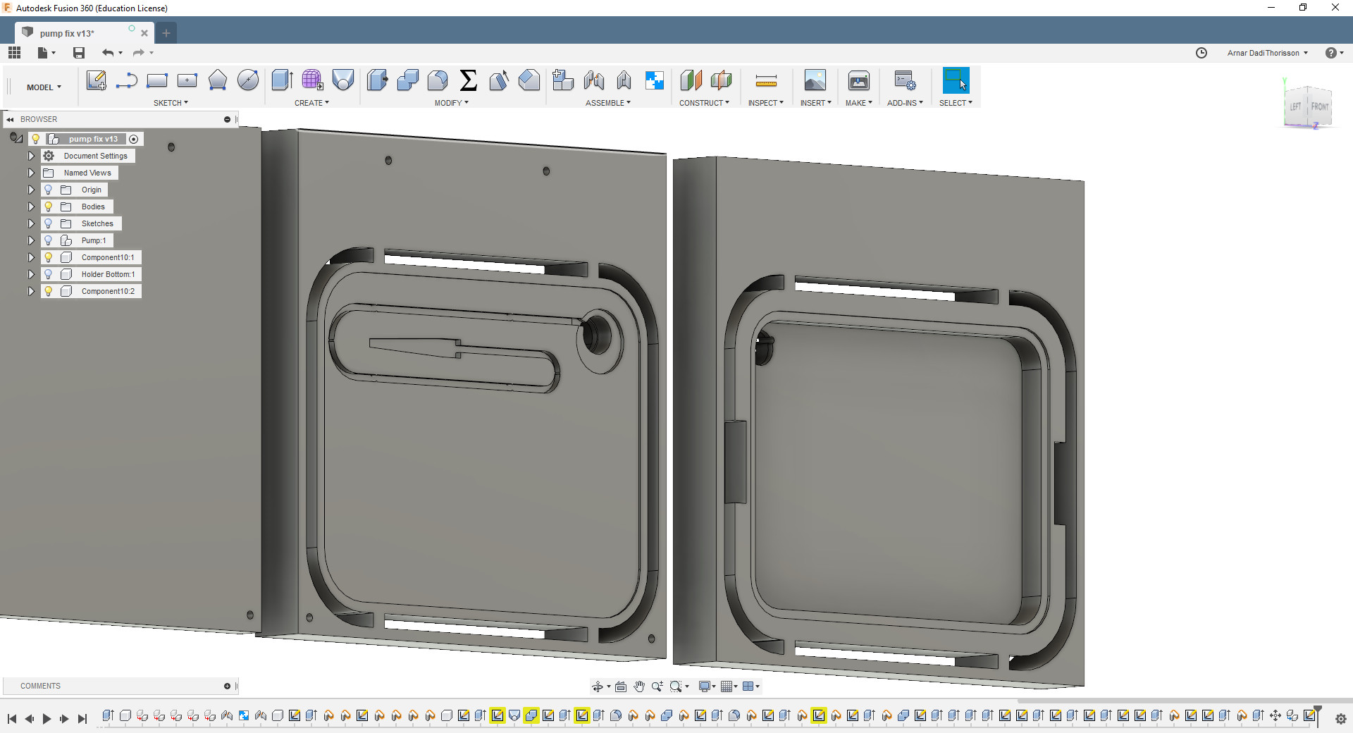 The design was set up in fusion as a 2 sided milling job. What I encountered in that journey was that I had trouble with was making the toolpaths in fusion with the 2d adaptive tool cam. I kept on getting the
Warning: "Lifting retract plane to feed plane".
The error was more than likely to cause damage to either tool, machiene or project. It kept rendering inefficient milling, mixing the order of cutting out the hole for the motor. (Smoothing toolpath before clearing out toolpath).
The design was set up in fusion as a 2 sided milling job. What I encountered in that journey was that I had trouble with was making the toolpaths in fusion with the 2d adaptive tool cam. I kept on getting the
Warning: "Lifting retract plane to feed plane".
The error was more than likely to cause damage to either tool, machiene or project. It kept rendering inefficient milling, mixing the order of cutting out the hole for the motor. (Smoothing toolpath before clearing out toolpath).
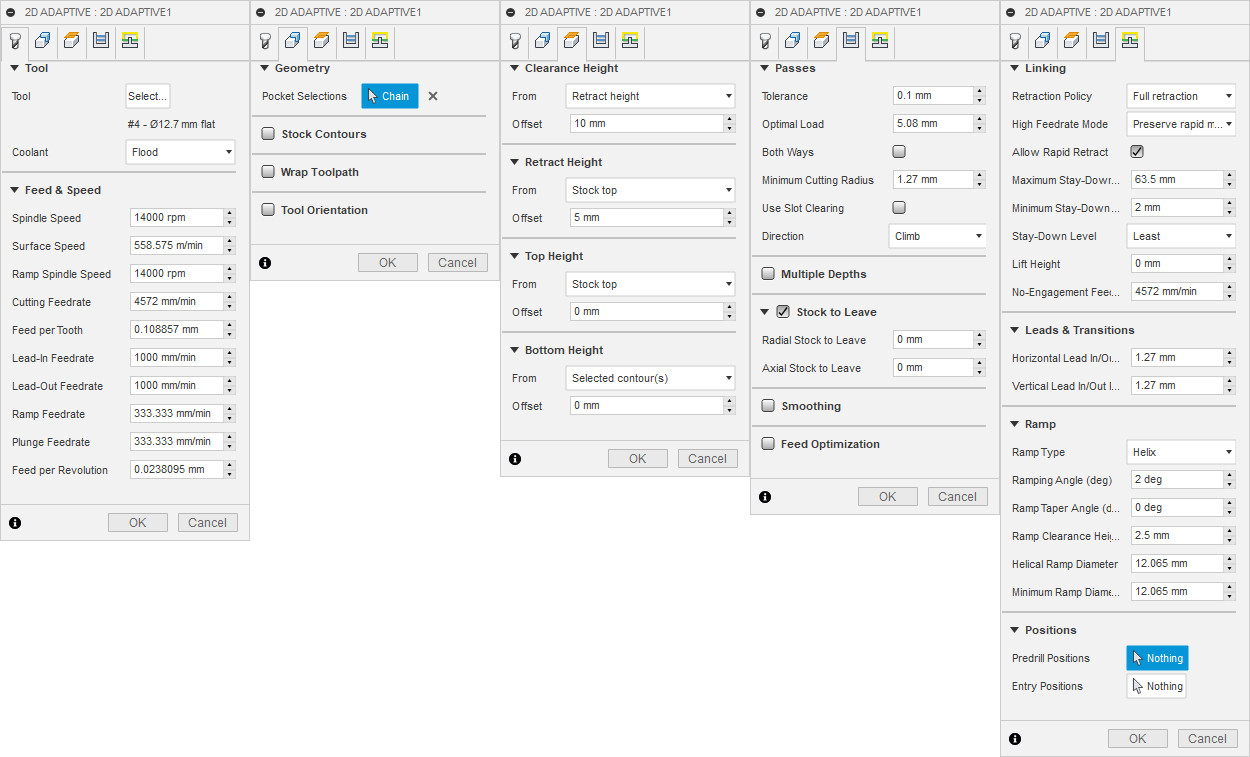
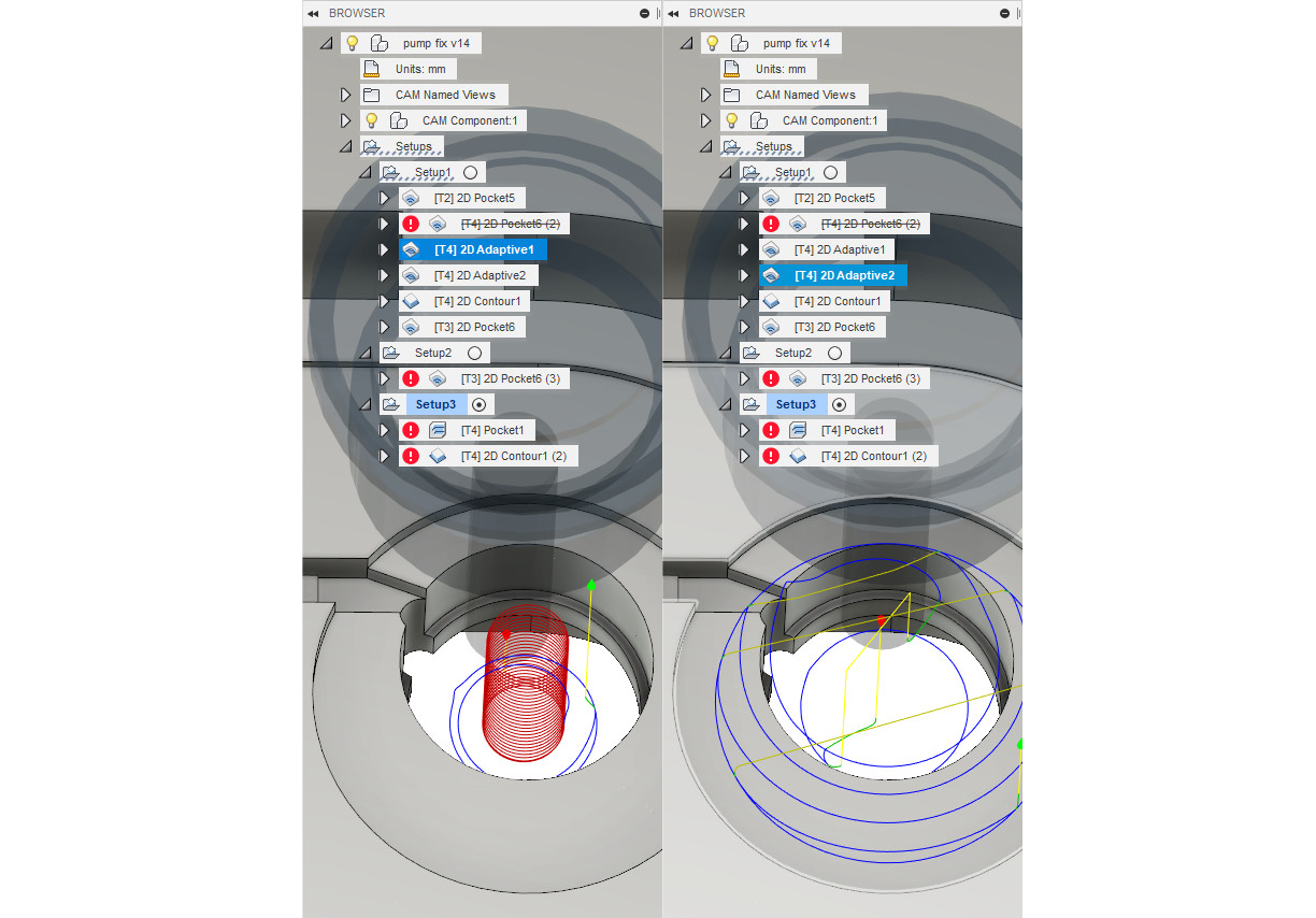 I tried a lot of different setups, to no result. I think that there were still conflicting settings in the ramp clearance height somewhere. After conseling from Bas, we decided to set up a new cam toolpath, changing from 2d pocket to 2d adaptive clearance cam, and for some reason the error did not reappear.
As a genaral note there still seems to be mysteries when setting up a cam job via fusion. For this project troubles were there when working with the 2d adaptive clearing toolpath, but I encounter no troubles when I try for a similar result with 3D settings.
Programming
Accelerometer
To simulate a scooping motion with electronics I used a device called
accelerometer
to measures it's tilt position. I chose to work with a commercial board because the
SMD accelermeter
that we have in the Lab´s inventory has its solderingpads on the bottom. Which means that mounting this on a locally made board is only possible via reflowing technique which our FabLab does't have the suitable equipment for that available.
What I did was to connect the accelerometer to a commercial arduino board which in turn is connected to my computer to see if I could read the values it sends and simulate a scooping sequence. I opened the Arduino software, imported
this code.
This is a standard example code that I found to read out values from the accelerometer. To view the values the accelerometer send is to go to "Tools > Serial Monitor" in arduino. We made a
code
to detect each motion for a scoop and after the sequence we got a text that confirmed the sequence.
When trying to program the board from week 7 for the accelerometer, I encountered that the ATtiny 44 that I´m working with, has too little memory for what I´m trying to accomplish. Under the guidence of Bas, the way that we saw to reduce this, is by removing the soft serial library and taking out the floating points variables. Unfortunately after removing all the floats from the code, the reading from the sensors proved to be too unstable to work with.
Button
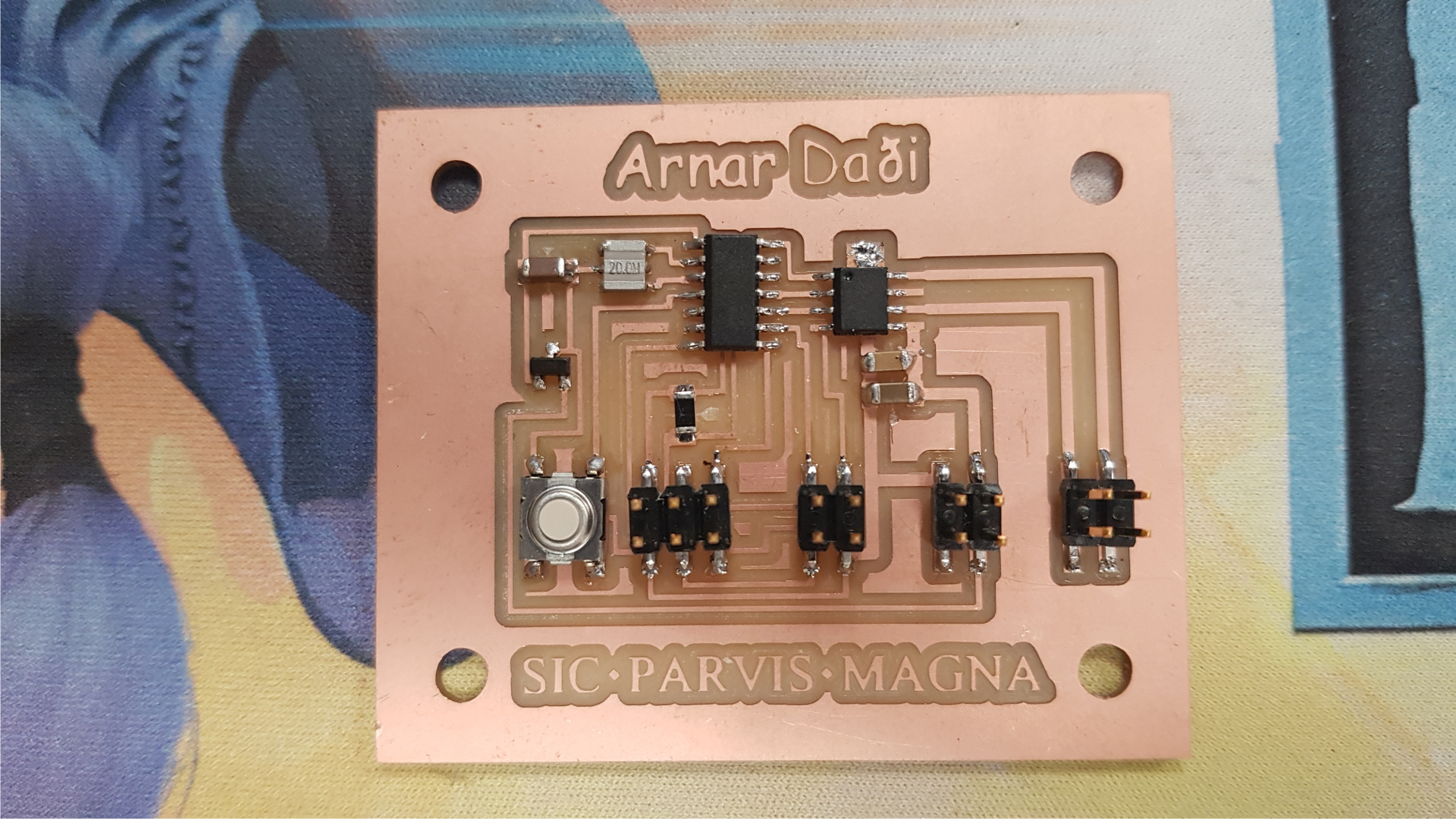
We assumed that we could've made the accelerometer work, hence the board is designed for a ATtiny 44. The next step was to make the board and it has one 6 pin for programming, three 4 pin, one for the accelerometer, another for the power and the last one for the motor. I used a 12v dc adapter to power everything and 5v regulator in the board.
At the time, redesigning the board with a bigger chip was not an option because I was getting too close to the final presentation deadline. Instead I had to go for plan B and simplify my spoon prototype by using a button as input instead. The button is connected to the 6 pin header (miso pin on the ATtiny44).
The first time I tested the
motorboard
it did turn on and rotated in one direction. But in my test code I had written a delay and that did not seem to show when I ran the board. At the time I decided to leave this problem be and sort it out later. Bas later realized that there was a typo in the code, a certain definition that was not correct (don´t remember exactly the details, but I think there was an "if" statement with missing curly braces or so) but it got swaped and after the motor was acting as expected.
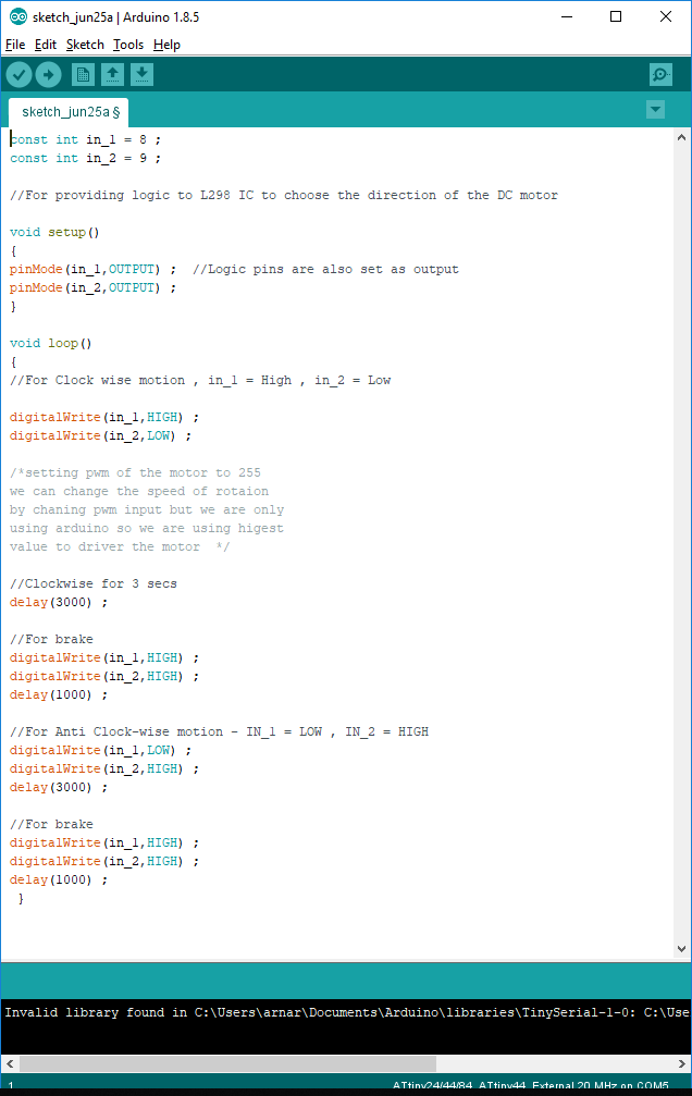
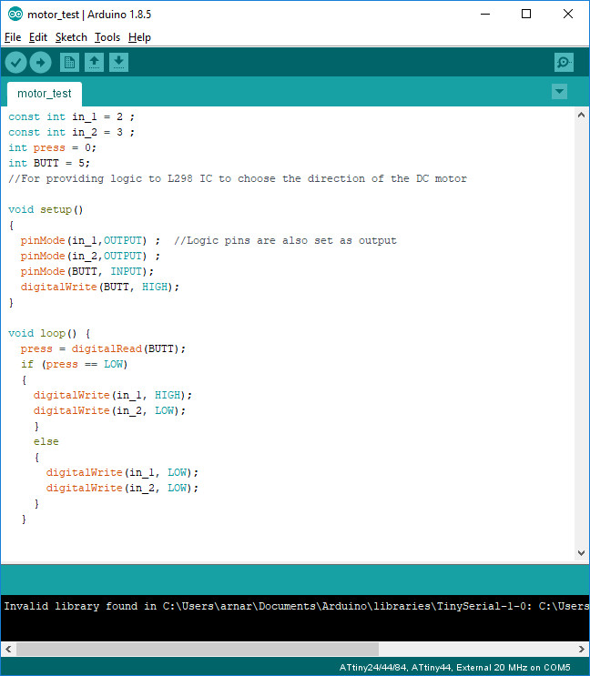
The only thing left was to add a button into the code and make the motor move when pressed.
Here I talk more about the accelerometer.
The Milling
First I started with the surface planer the sacrificial bed to get a smooth surface.
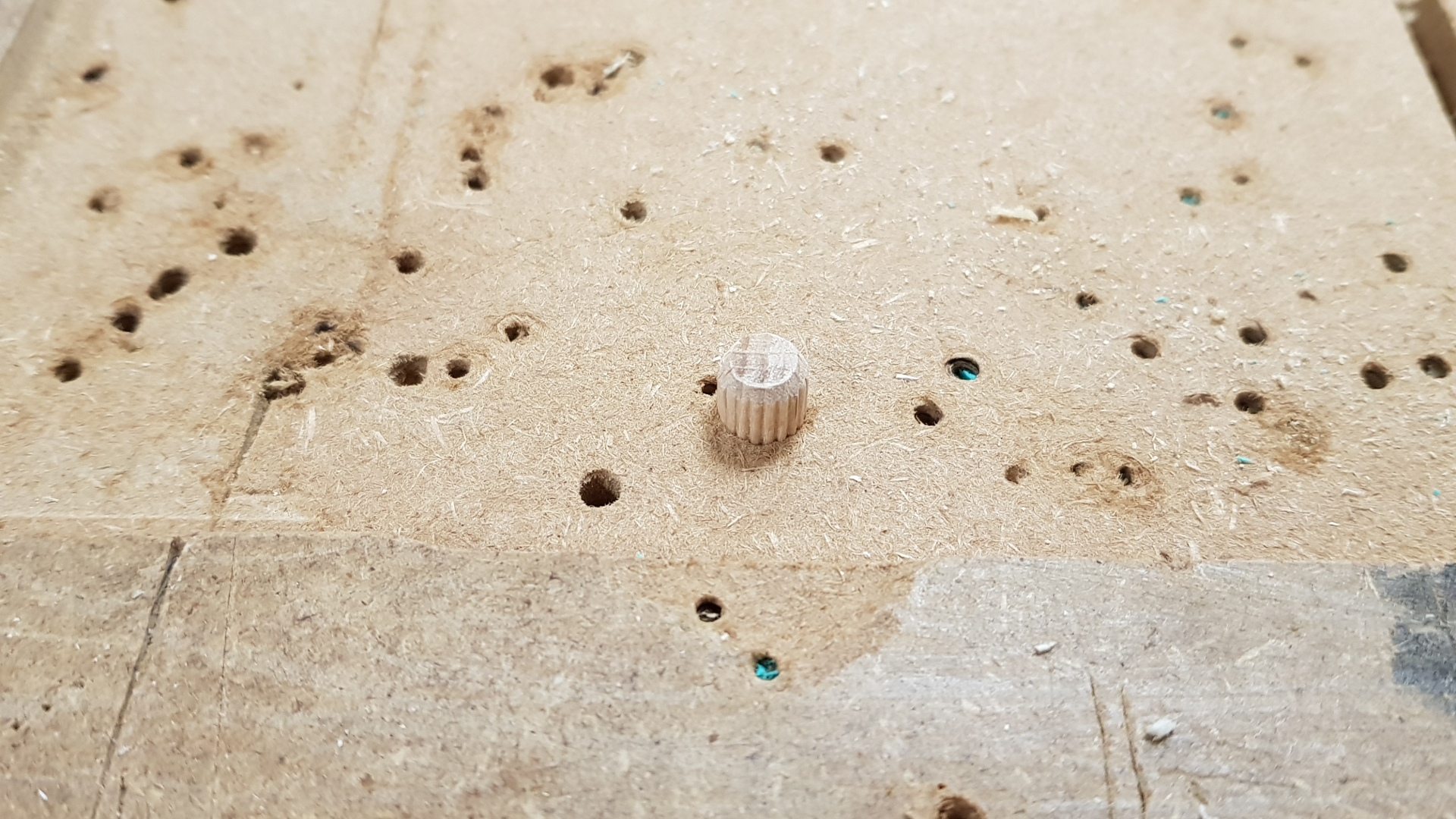
 When making a double sided mill it's good to have some sort of guidance points when rotating the block. I made toolpaths for each side and for rotating the block I created holes to position it. I designed holes for dowels and mirrored them to create the holes for the sacrificial bed. Hence when rotating the block I could put in the correct spot. There was a very minor missalignment because the holes in the bed were a bit smaller and we had to drill them to fit the dowels (it was ~0.1mm).
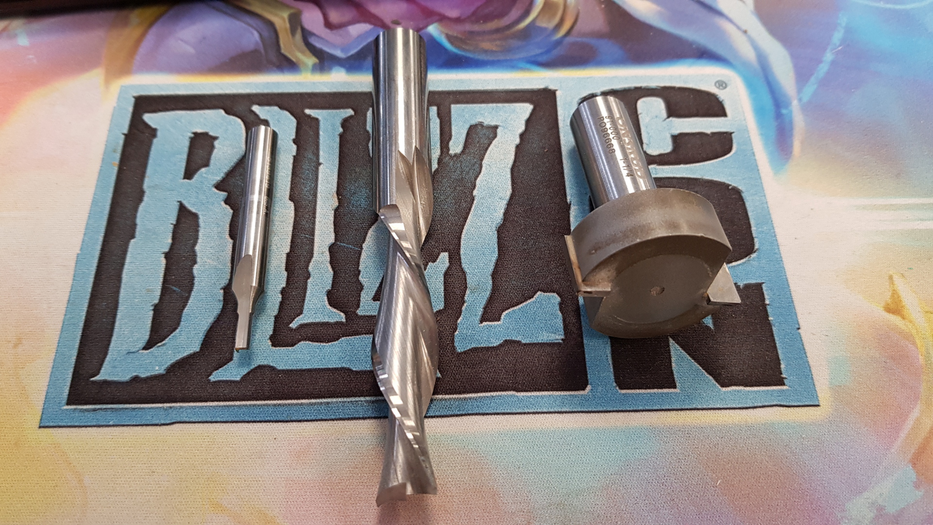
 The plan is using these 3 tools.
- 1/4 inch straight endmill for milling the holes for dowels
- big plainer for sufacing the edge in the top of the tray
- 1/2 inch down cutter for milling the motor hole and then cut out around the board
- 1/4 inch straight endmill for the small cable gutter.
- Flipped the board.
- 1/4 straight endmill for milling the holes for dowels
- 1/2 inch for the whole backside
 The dowels needed just a little hammering down.
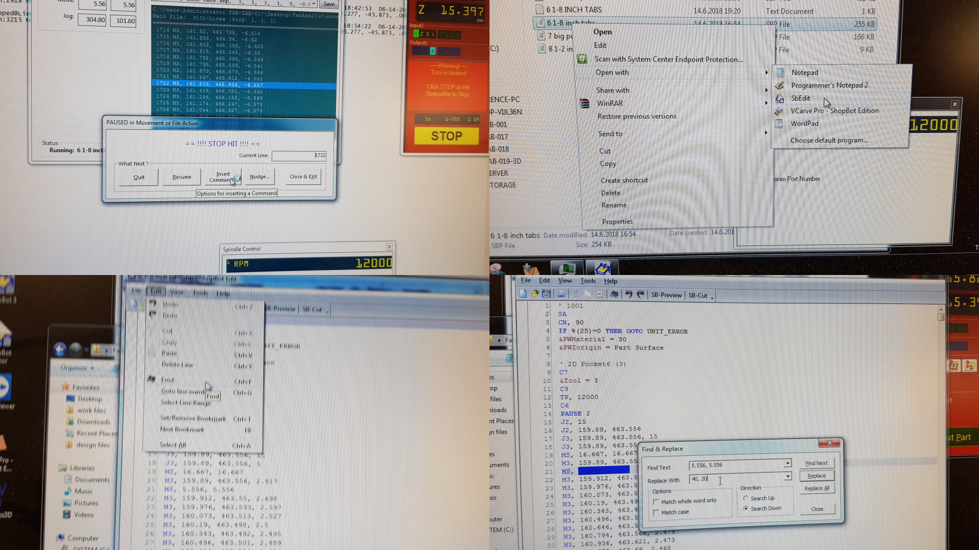
 I had minor issues that the stepdowns were rather slow and the settings in Fusion didn't allow me to change the settings. So Bas showed me a workflow to change the speed in the g-code itself. To do that we opened the code with the Shopbot editor and used the find option to replace all the codes that were for the stepdowns and changed them to speed it up.
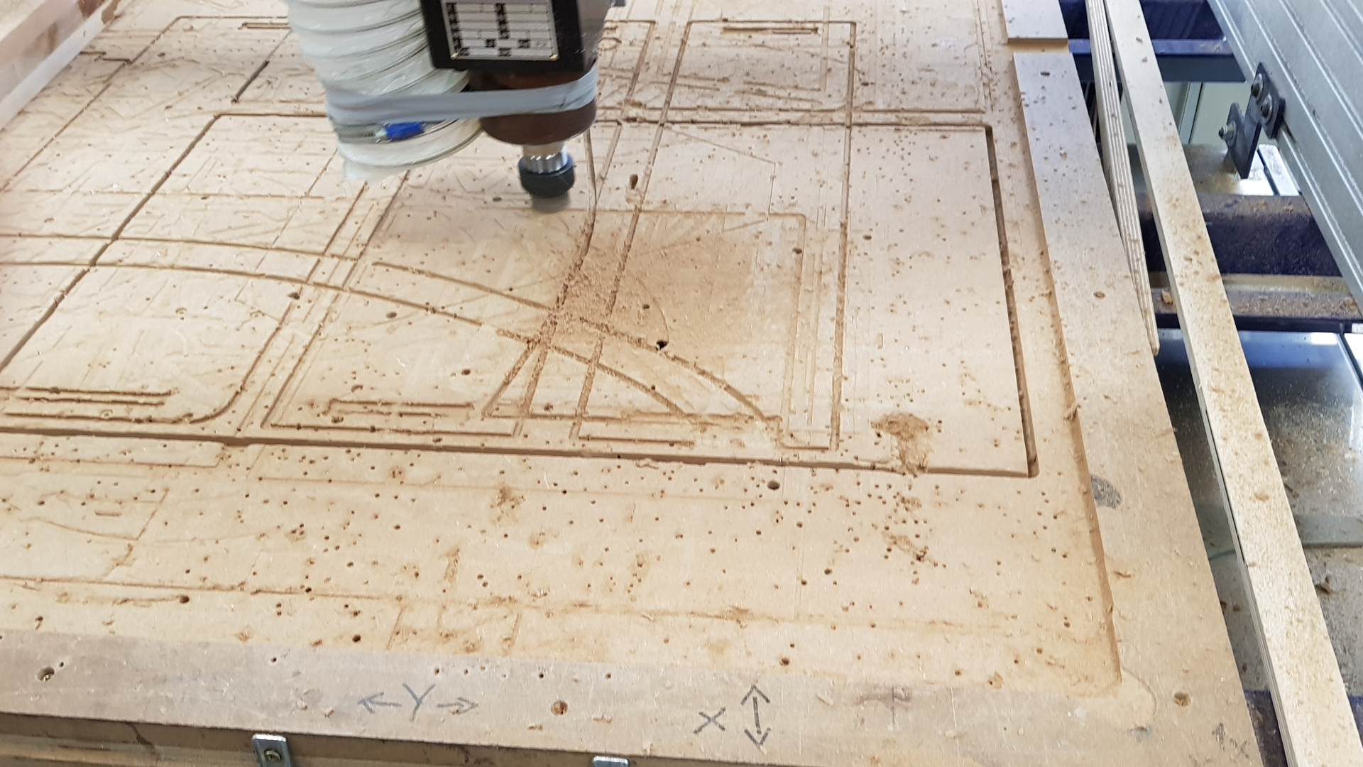
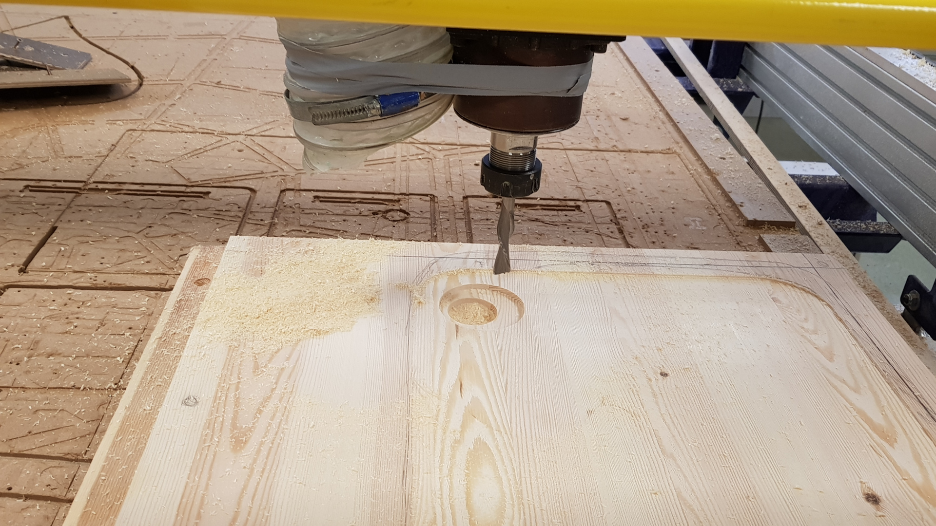
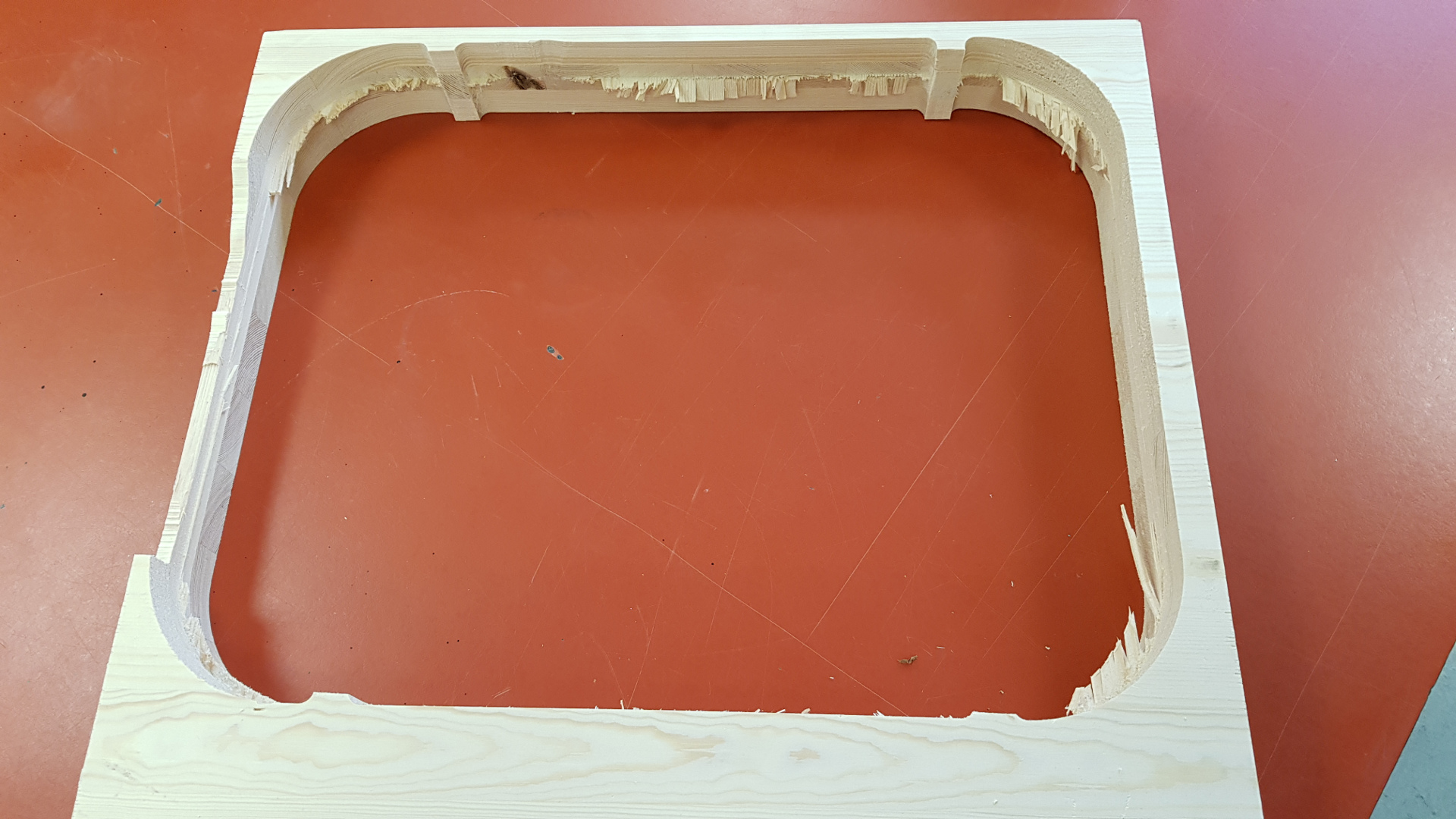
 One problem I encountered in the shopbot is that the tool began to mill further down and it was supposed to. The tool loosened up and that would have caused a broken tool and maybe injuries, so always pay attention to the machine when running it to prevent accidents. I had to tighten the tool again and since it dropped, the z home was higher than the tool so I also needed to zero that again.
 I should've made the backside milling a little bit deeper since there was a small amount of material left between the cutouts.
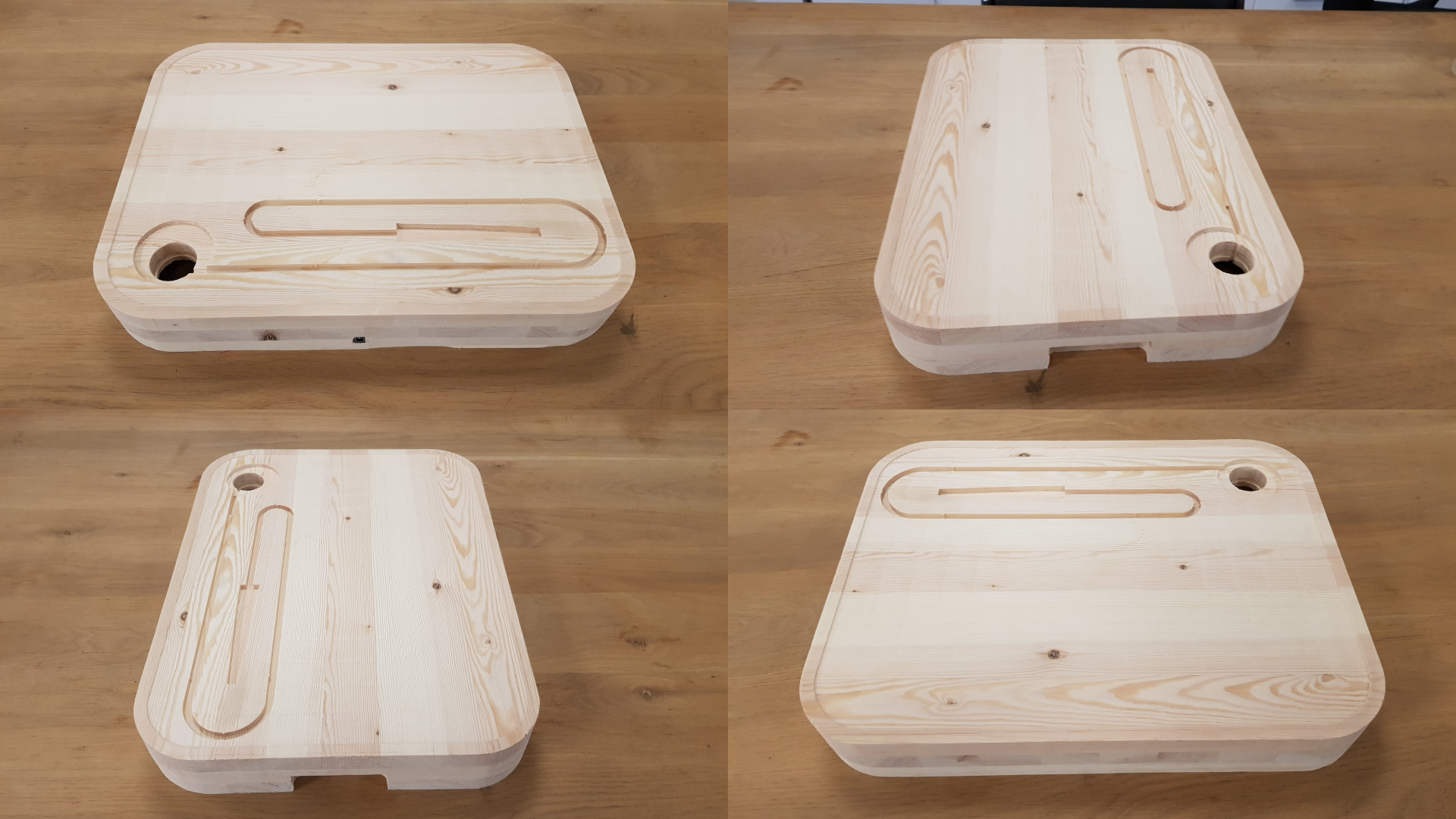
 In the design I put tabs in the tube holder so it would be snuggly fit in, a cut-out for the spoon holder and a hole for the motor is just tight enough so there is no mount or glue needed.
3d printing
lasercutting
Assembling
 As meantioned before, to exceture plan B I needed to add a button to my prototype. I made the needed adjustments in fusion to my spoon holder and 3d printed it again. Then I sanded the shape and spray painted it with white primer. On the motor circuit board I connected the button to a unused pin of the 6 pin programming header which connects to the microcontroller.
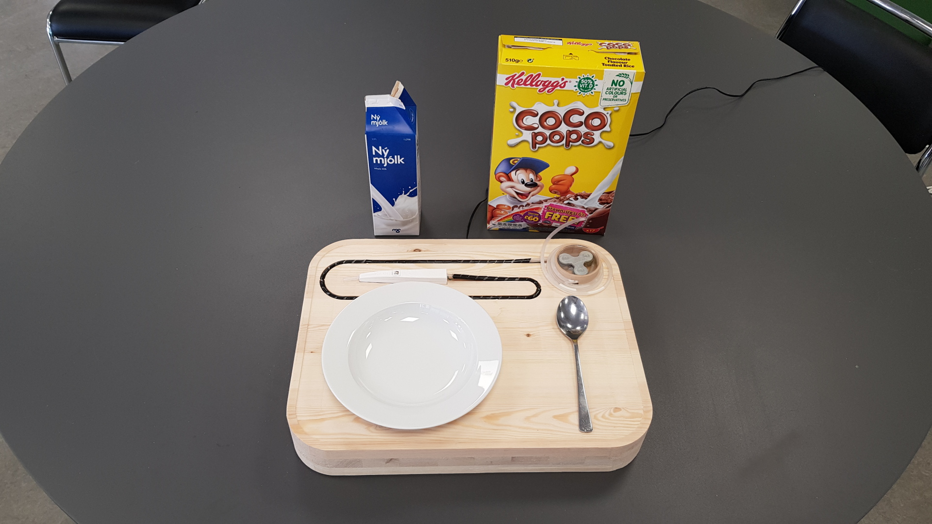
Next up was to assemble everything and test it out.
After playing around with it, it worked exactly like intended.
As meantioned before, to exceture plan B I needed to add a button to my prototype. I made the needed adjustments in fusion to my spoon holder and 3d printed it again. Then I sanded the shape and spray painted it with white primer. On the motor circuit board I connected the button to a unused pin of the 6 pin programming header which connects to the microcontroller.
Next up was to assemble everything and test it out.
After playing around with it, it worked exactly like intended.
Fusion file
Toolpaths for Tray
Spoon Holder 3D Files
Pump 3D Files
Circuitboard Outline png
Circuitboard Traces png
Circuitboard Arduino Code
Eagle Board Design
Eagle Schematic Design
Aftermath
Bill of Materials
- Acceleromoter (commercial board). 1500 kr
- 3d printed spoon handle (100 grams PLA). 1000 kr
- Tube. 800 kr
- 3 bearings (salvaged from used thrift store skateboard). 1500 kr
- Plexiglass circle to cover pump. 500 kr
- 3d primted perostoric pump (200 gr PLA). 2000 kr
- 12 volt adapter. 6000 kr
- Plastic cable management wrap around 300 kr
- Motor board (including smd parts, copper plate) 3500 kr
- Block of wood (glued together bars of wood) 6000 kr
total : 24.600 kr - ~200 euro
Conclusion
I'm a staff member of FabLab Reykjavík and my main reason for taking this class is to enhance my knowledge and skills to teach others. For this semester and final project I learned great deal. I'm a learner by doing.
My weak points were the electronics and discipline on documentation. Realized that it will just take more time then avarage to get my thought into words. I was able to turn thoughts into a real project.
The most valuable skilles that I learned were being able to make electronics from scratch, searching for information and where to get it and most of all being able to teach others what I've learned.
My skills in Fusion were rather basic when I started and I think it's safe to say that I've grown to an advanced user, at least concernig parametrics and designing. I also rediscovered that I'm good at math was able to put that into use in Fusion.
Special Thanks
I want to thank Linda, my instructor for EVERYTHING that she has done to help me with this class. Could not have done this without her.
