Group Project
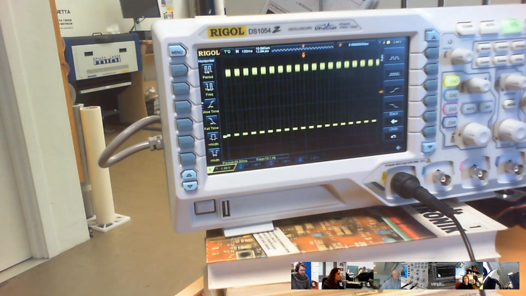
For this weeks Group assignment we had to test the equipment in our lab to observe the operation of a microcontroler circuit board and on monday we had a vidoe call meeting where Vilhjálmur from FabLab Höfn showed us through using the oscilloscope. Also Linda linked a
site on how to use it.
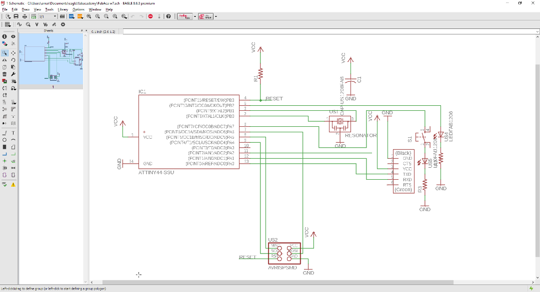
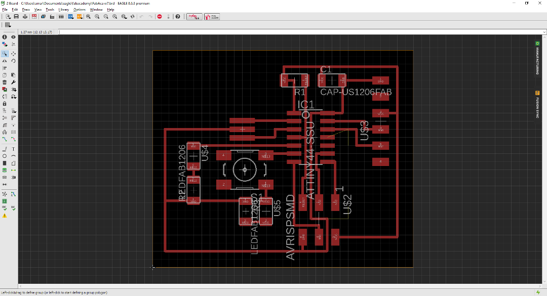
Making the Board
For this I needed to draw the hello world circuit board and I use Eagle from Autocad to set up the components and draw up the circuit. The line width is set to 0.36mm and one handy feature was to use properties to move the traces a fraction of a millimeter so for instance couple of lines could go under the microcontroller.
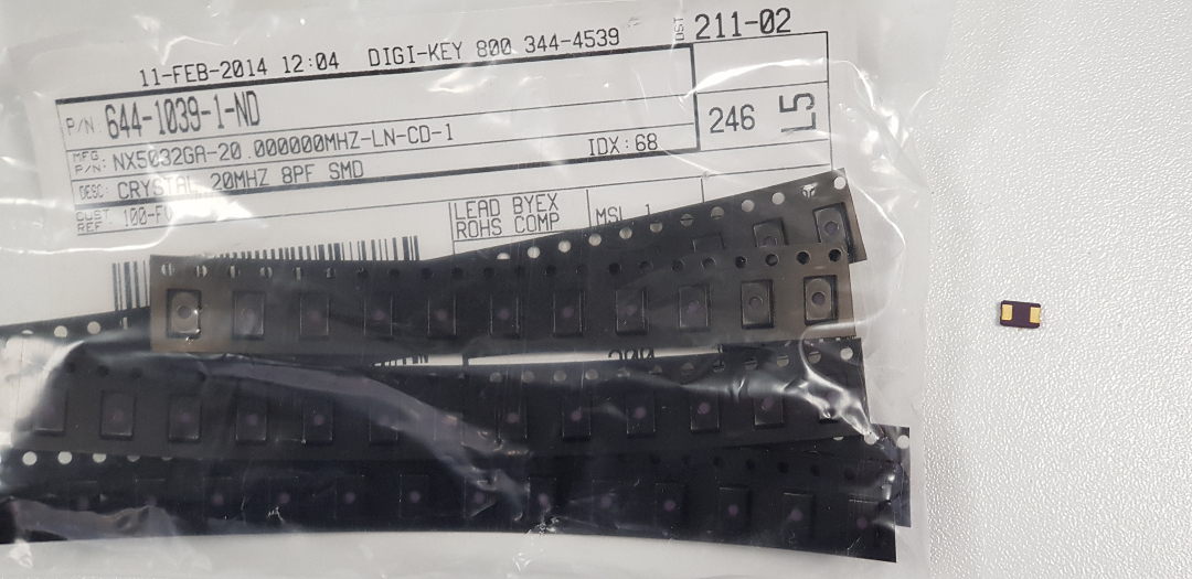
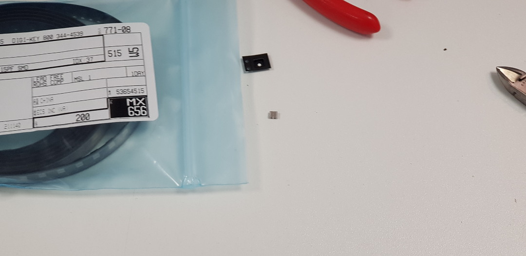
Next was to mill the board out and solder the components on. We found a crystal 20Mhz but was 2 pin and found no crystal that was 3 pin so we asked Bas about it and we found out that resinators are very similar to crystals, there are minor differences but not that much that it would make a difference.
After a discussion with Linda about resistors with LED's I decided to test out the difference with different resistor with the same coloured LED's.
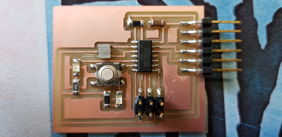
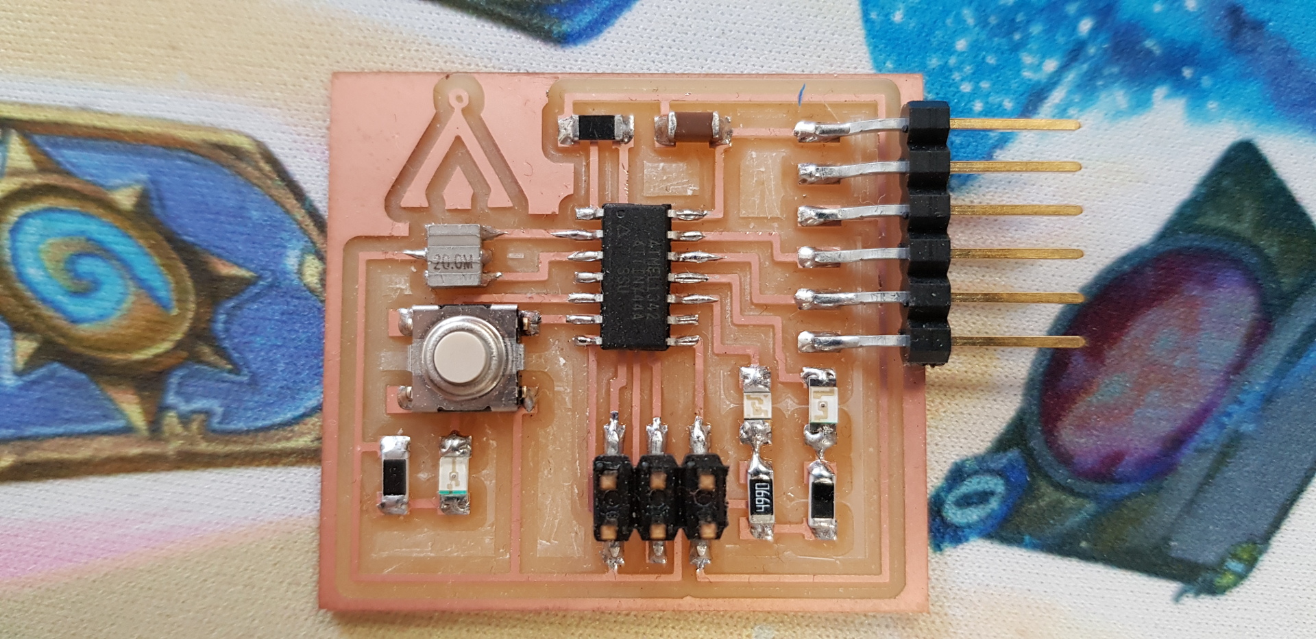
The result was that that if the resistor has a lower value the light shines brighter and vise versa with a higher resistor. After that Bas walked me through getting the board ready for programming. I made another board where the LED wasn't connected to the button.
Programming
I used the
arduino
software to program the board and to see what pin belonged to what number.
Here is a tutorial on how to program an ATtiny w/ Arduino
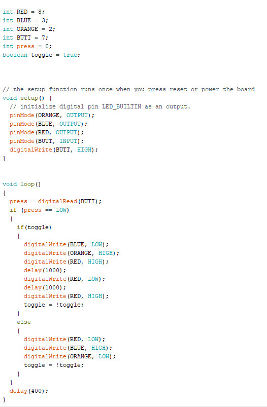
I used toggle command to change the state of the LED in the code that's in it. I also used the loop with delays to see different outcomes and I also tried making it be in different loop if I pressed the button and used "while" code but I couldn't get a loop going but the state of LED's was still so I managed to change the state of the LED's with the button.
Arduino Test Button File
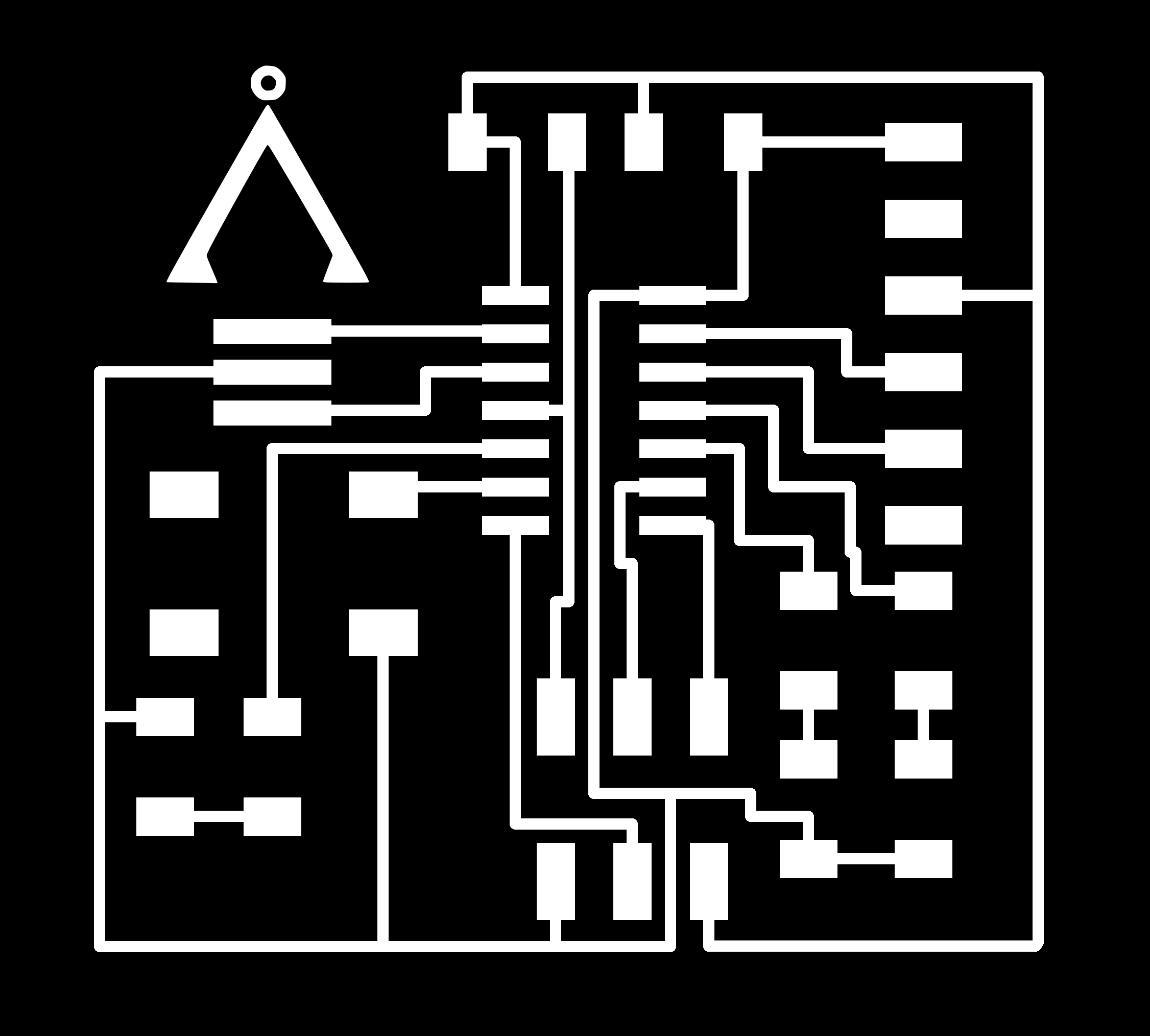
PCB Otline File
PCB Traces File