
1
Since for my “Thousand shades of crane” Final Project I planned to use RGB LEDs to generate the thousand different shades, I choose the RGB LED ATtiny45 board for this week’s assignment. In earlier weeks we learned how to use an ATtiny to control a single color LED and how to fade in/ fade out by using Pulse Width Modulation and the analogWrite() command. Also, I had done already RGB LED color cycling with an Arduino using that analogWrite() command, connecting the RGB LED to 3 pins allowing for Pulse Width Modulation (in this case I used pin 9, 10 and 11), marked PWM (see real-world Duemilanova on the left) or with a tilde (see Arduino Uno Fritzing drawing on the right).

2
With this in mind I thought it would be simple to shrink the Arduino version down to an ATtiny chip, but looking at Neil’s hello.RGB.45.c code it seemed a lot more complicated than that. Also, I my notes it said Neil was doing Software PWM. I wondered why not just doing hardware PWM, so I took a closer look at the description of the ATtiny45 pin configuration and Chapter 11 (8-bit Timer/Counter0 with PWM) in the Datasheet. I then realized the ATtiny only has 2 PWM channels (which I could have known earlier if I would have read the features list on the first page more carefully!), so hardware PWM to control the 3 channels of an RGB LED was not possible, hence the need to solve this in software.

3
Next step was to make the board itself. First I quiet literally copied Neil’s board and redrew the schematics in Eagle: Attiny45 (IC1) with 10k resistor (R1) and 1uF capacitor (C1), programming header (J1) to be able to program it, 4 pin header (J2) to bring power in from power supply, power through a regulator (IC2) to filter it, RGB LED (LED1) with current limiting resistors of 1k for R (R3) and G (R2) and 499 ohm for B (R4) because it is less efficient and needs more current), common anode connected to the high voltage side.

4
When switching to board mode I noticed the copper pads for the RGB LED were far larger than on Neil’s board (I assume this had to do with heat dissipation). This gave a problem leaving not enough space for some traces. To solve this while still keeping the board as small as possible I added a zero resistor (R5) to the board.

5
I saved the traces and outline of this revised version and took it to the Modela-20 for milling. Using the Fab Modules for this I had no problems milling it.

6
I did not encounter big problems with soldering all components on the board either, using the part list that (as I discovered only now) can be generated by Eagle automatically.

7
Step by step following the same document as used in week 11 for Input devices, programming the board with the hello.RGB.45 C code and makefile, using the ISP in-circuit programmer, went very smoothly too. My main problem was to understand how the Software PWM worked. I found this tutorial very helpful to get a better understanding.

8
The end result of designing, milling and soldering RGB LED boards can be seen in this picture. Apart from the original one on the left, I later made several other RBG LED boards, amongst which the two other boards in this picture. Both were designed to be used as a node in a network (see Week 15) with a Hall sensor as an input device, the one on the right being the definitive version of the board as used in my Final Project (see Final Project).
9
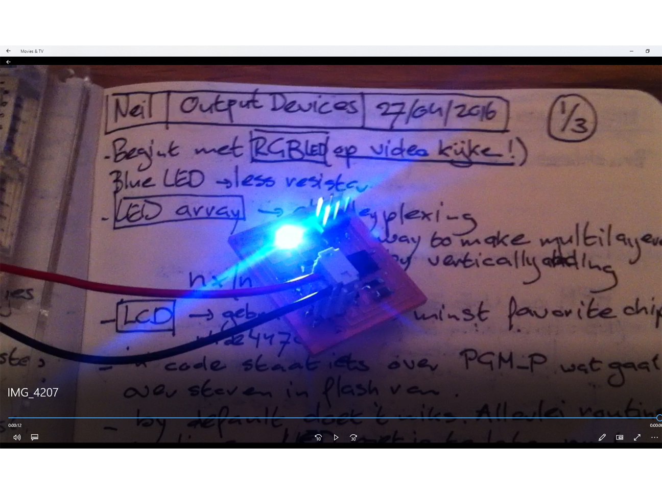
A video of the result of this week’s assignment showing the RGB LED on the board colour cycling through the colour spectrum, can be found here.
FILES: All files of this week can be found here.
