Assignment: Make something big.
For the group assignment we got introduced to the ShopBot and told how to operate it safely, by wearing safety glasses and earmuffs and with no loose hair and clothing near the moving parts.
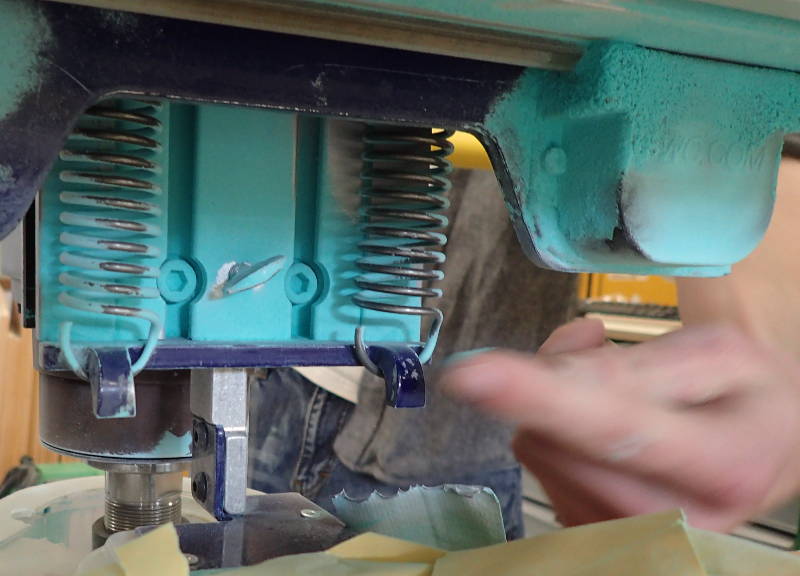 We were shown how to loosen the dust extractor and clean it, there was quite some dust and melted chunks of material left over from a previous job.
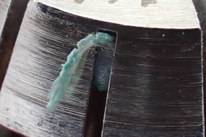 The collet must be clear of foreign material, this came off with a toothpick.
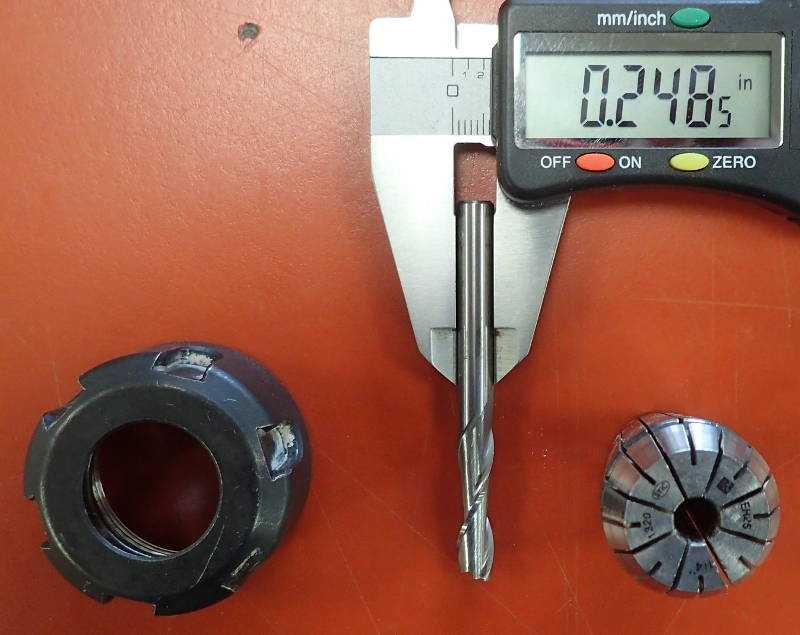
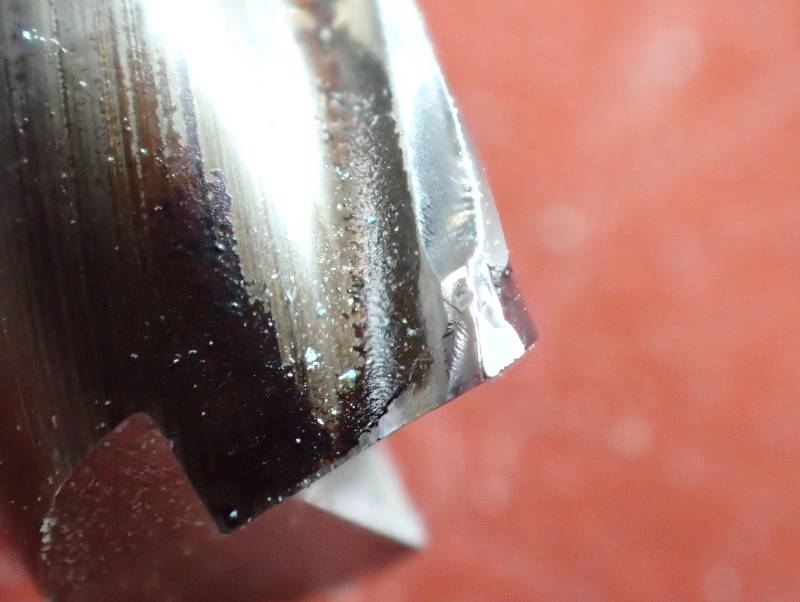 The bit is slightly chipped, but still servicable.
 The large collet is nearing the end of it's service life, but has not slipped yet.
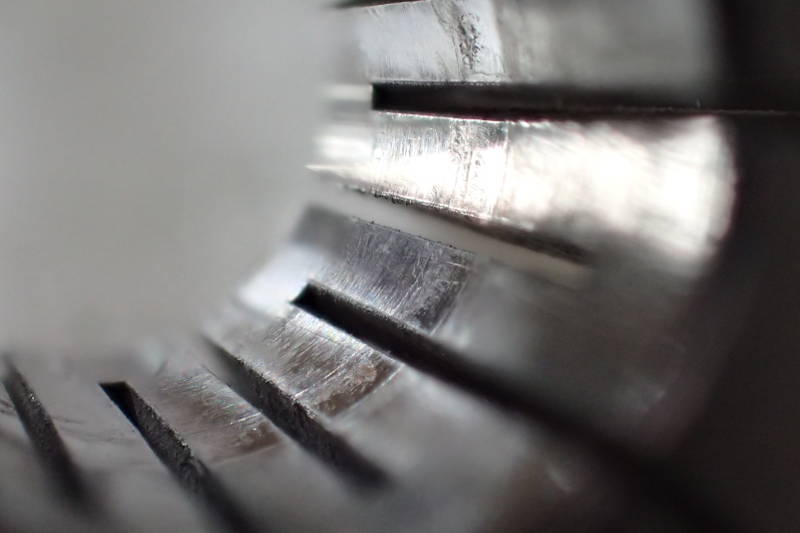
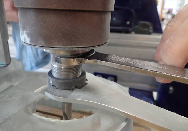 The bit being freed from the collet.
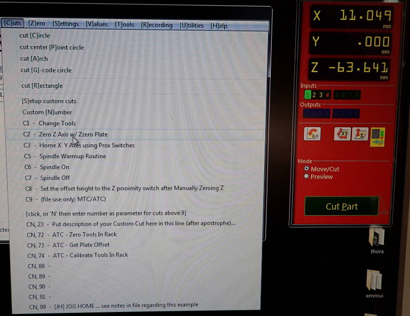 Before use, the spindle must go through a warm-up routine for 10 minutes.
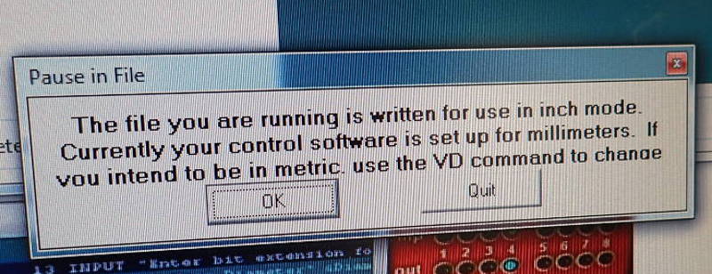 We must make double sure whether the job is in mm or inches before exporting the toolpaths.
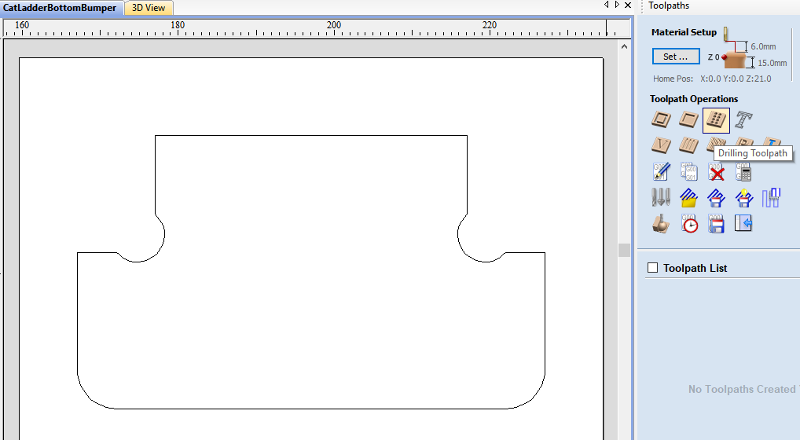 In VCarve Pro, I like to make three toolpaths. The first one a drilling toolpath and in this instance, two profile toolpaths, one using a downcut bit that will cut 4mm down and the other using an upcut bit that will start it's cut at 4mm and continue through the rest of the material, i.e. the material thickness minus 4mm. This way tearout is minimized or even eliminated, as the bit will be cutting away from the surface of the material, towards the middle. It is also good practice to make the bit cut slightly, say 1mm through the material into the ShopBot's sacrificial bed, if the sheet material used is at all buckled. Otherwise the bit may not cut quite all the way through, necessitating some careful and time-consuming cutting to break it free and sanding afterwards, with increased risk of accidental tearout. This last pass will also have tabs, to ensure the piece will not break free during the last pass and fly across the room with great force.
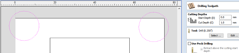
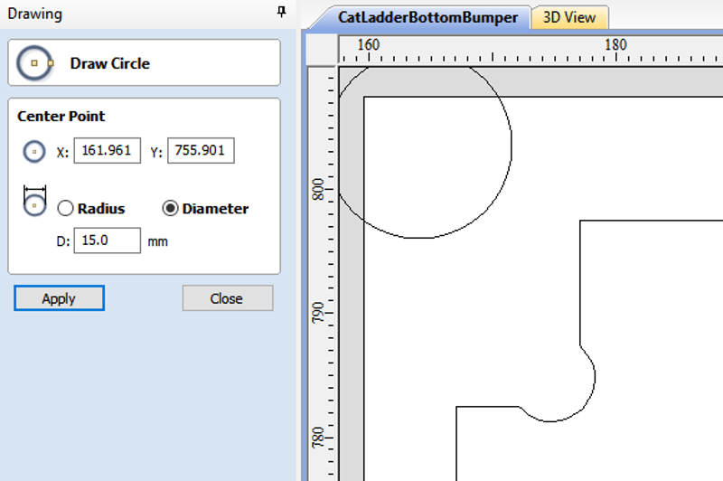 For the drilling toolpath, I like to draw a circle that is twice the radius of the bit I will be using and place it outside the object's outline, with some distance to spare. The distance between the circle and the object's outline will be the distance between the bit and the screw. The ShopBot will drill in the middle of this circle, thus handily avoiding a collision on the subsequent passes.
 I now select all and then press shift and deselect the main object, as it is a simple one with one vector, leaving the drilling circles selected. I set the cut depth to 1mm, just enough to make a mark in the material.
 Now fire up that ShopBot and drill away.. upon which it will hit it's endstops with a resounding KABOOM, which will startle you good and proper. But why...?
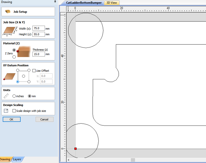 Because offsets. Those pesky things somehow connived to be selected and also set at some alarmingly large figure when VCarve was started. For fewer grey hairs, for a beginner such as myself, always make the first thing you do after opening a file in VCarve to go into Edit, Job size and position and set the material thickness, Z zero to the upper surface of the material and the datum position to the lower left corner. Set the offsets to zero, or better still, deselect them. When you have gained proficiency in operating the ShopBot and you have stopped giving each other nasty surprizes, then it's time to explore those settings to improve your workflow, but I feel going through this every time at first will make things safer and more straightforward.
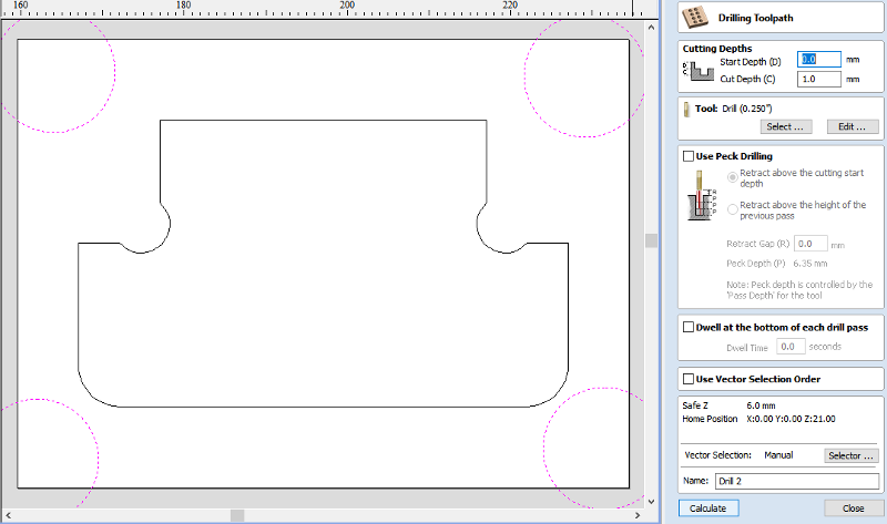
 Now the offset is at 0, cut depth at 1mm. Much better. The name VCarve chooses for this toolpath is good and descriptive, you can not confuse it with your other toolpaths - but, I like to change it to an awkward, long name that stands out like a sore thumb, in case the previous operator has left some similarly named files on the desktop and I might click on one of those by mistake.
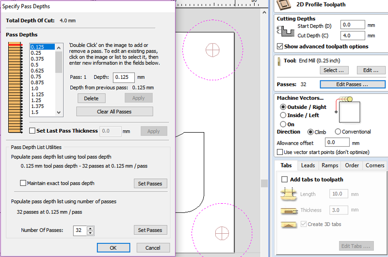 Now for the Downcut pass. It will be a 4mm deep cut but the ShopBot will default to an extraordinary 32 passes for this, which would take all day, so I click on Edit Passes and select Number of passes. I like to make a pass at most 3mm deep, so two passes will be fine for this 4mm cut. I type in 2 and press Set passes. What did I forget? To select the object instead of the circles from the first pass. Make absolutely sure none of those circles is selected, otherwise a collision with a screw is guaranteed. Having done that, check if the number of passes have to be edited again.
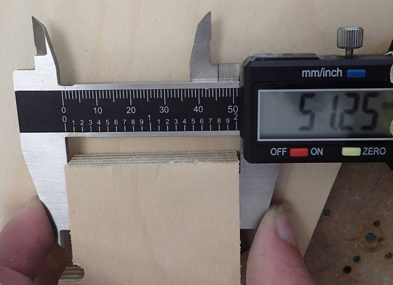
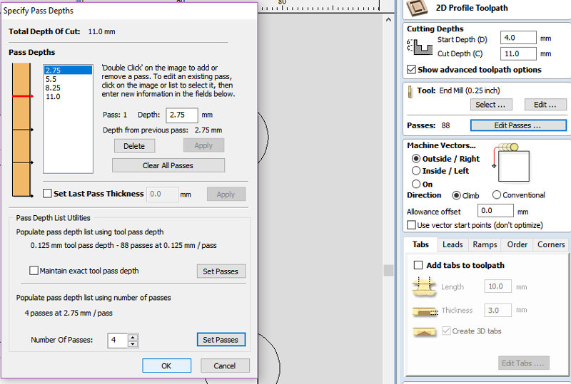 Now comes the last pass, an Upcut pass. This starts 4mm deep and as the material I'm using is 15mm, the cut depth will be 11mm. Make it 12mm if you are not sure your sheet material is flat enough for the bit to cut through all along the toolpath. The ShopBot will want to make 88 passes, so I change that to 4, bringing each pass comfortably under 3mm.
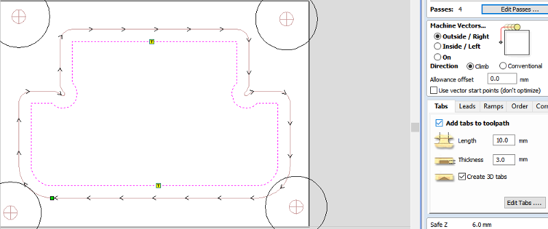 It is necessary to add tabs to the final pass, this piece is tiny, so I get away with two tabs, but with larger pieces the more tabs, the better. Time spent with a chisel punching the workpiece out afterwards is trivial compared to the grief sharing an enclosed space with a ballistic missile can bring.
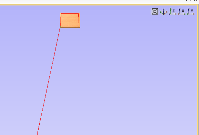
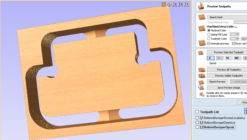 VCarve gives a nice preview of the selected toolpath, where you can view them in 3d and see if you have ended up with the right amount in the right places. Pressing the play button vill go through a virtual milling pass and show what the finished job should look like.
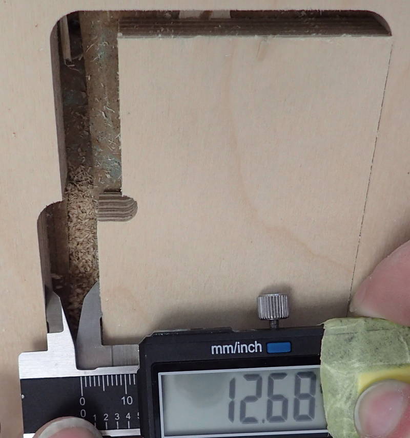
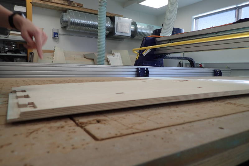 The stock can be quite bowed before it's secured to the bed.
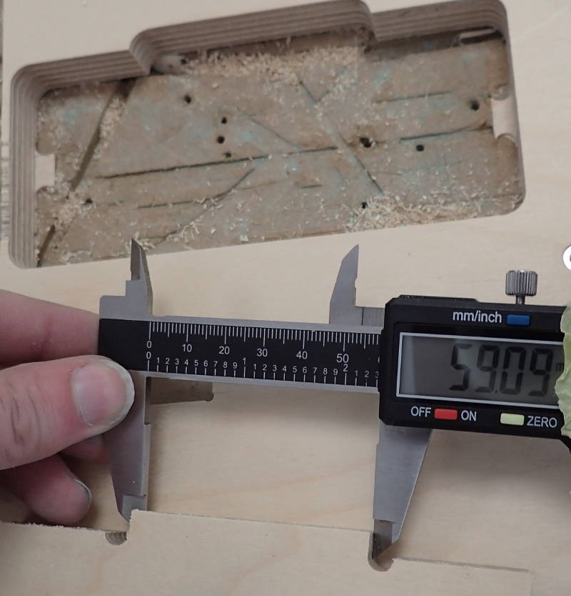
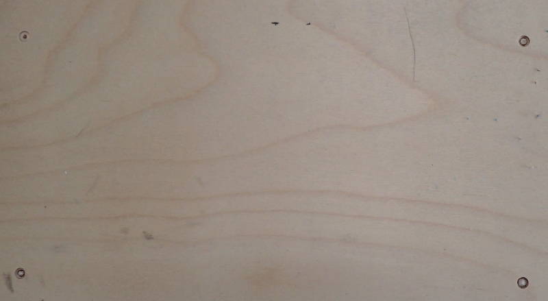 Screw pockets ready.
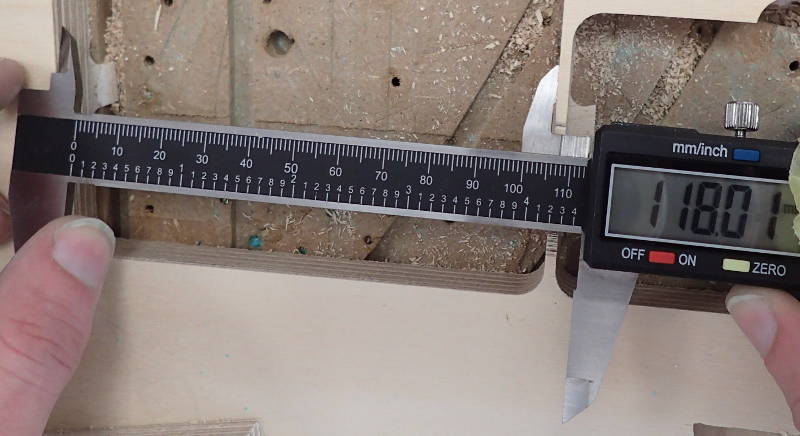
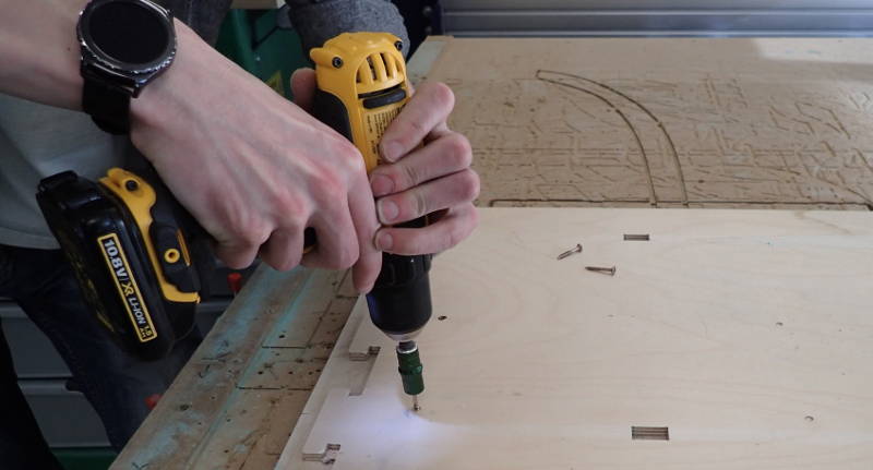 Workpiece secured to the bed.
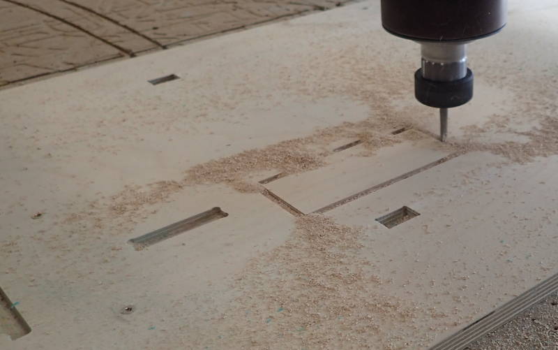 Milling started.
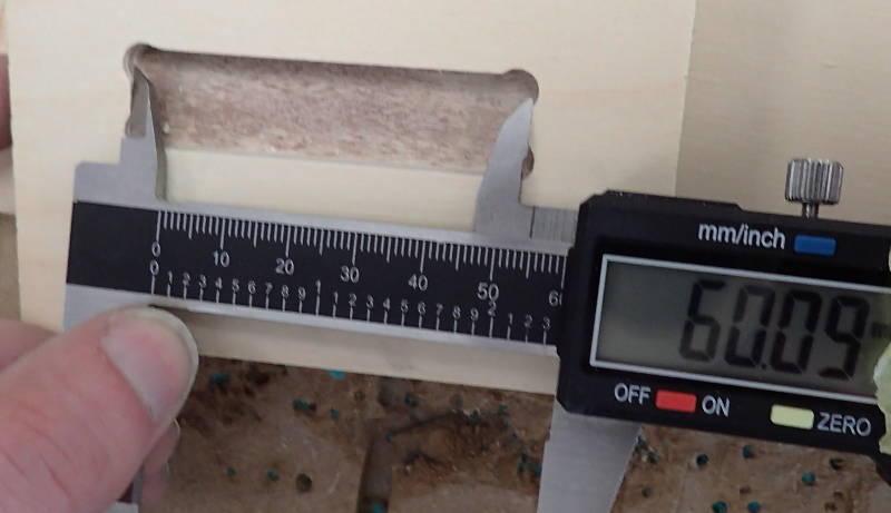
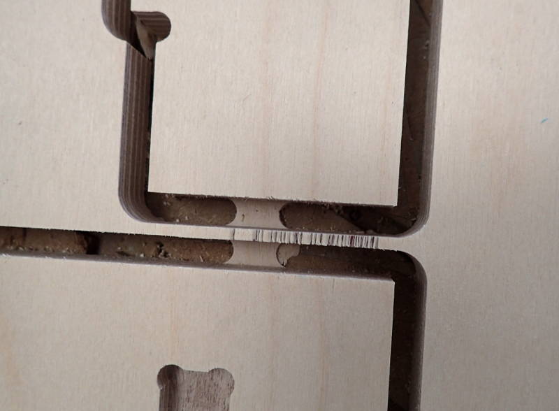 Those tabs make sure the workpiece stays put while milling finishes.
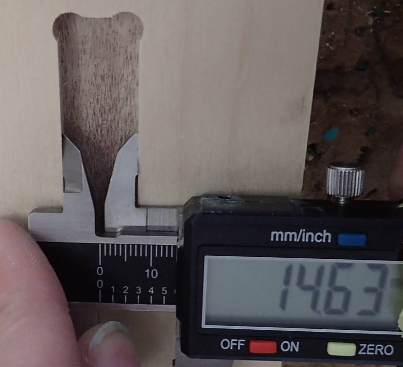
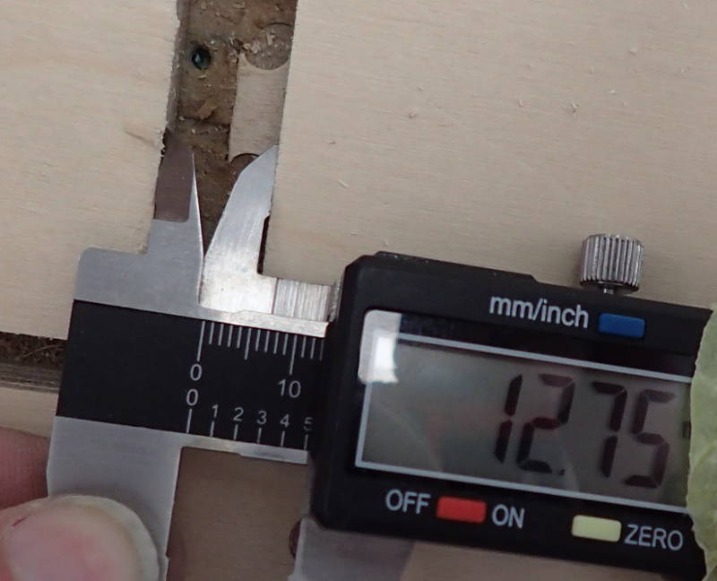
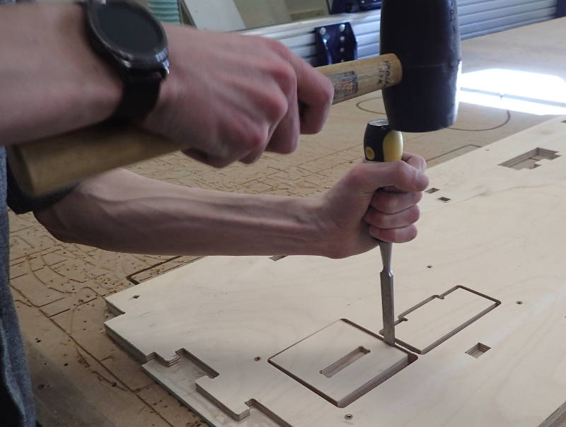 Cutting through the tabs.
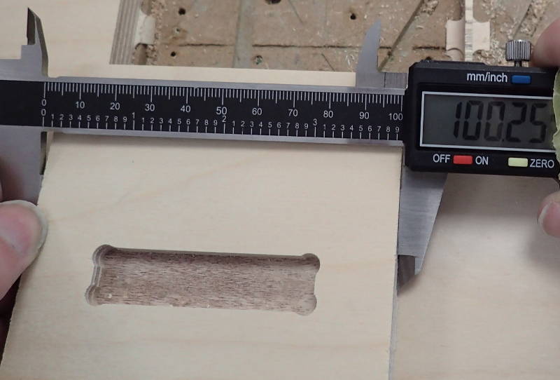
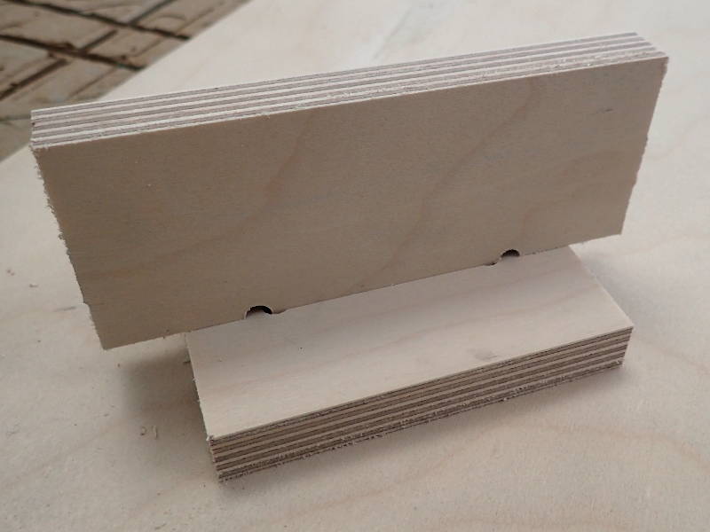 Finished demonstration piece.
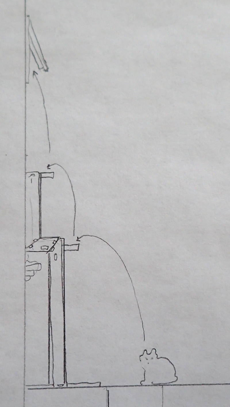
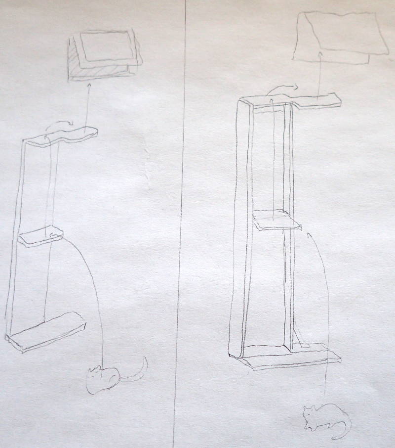
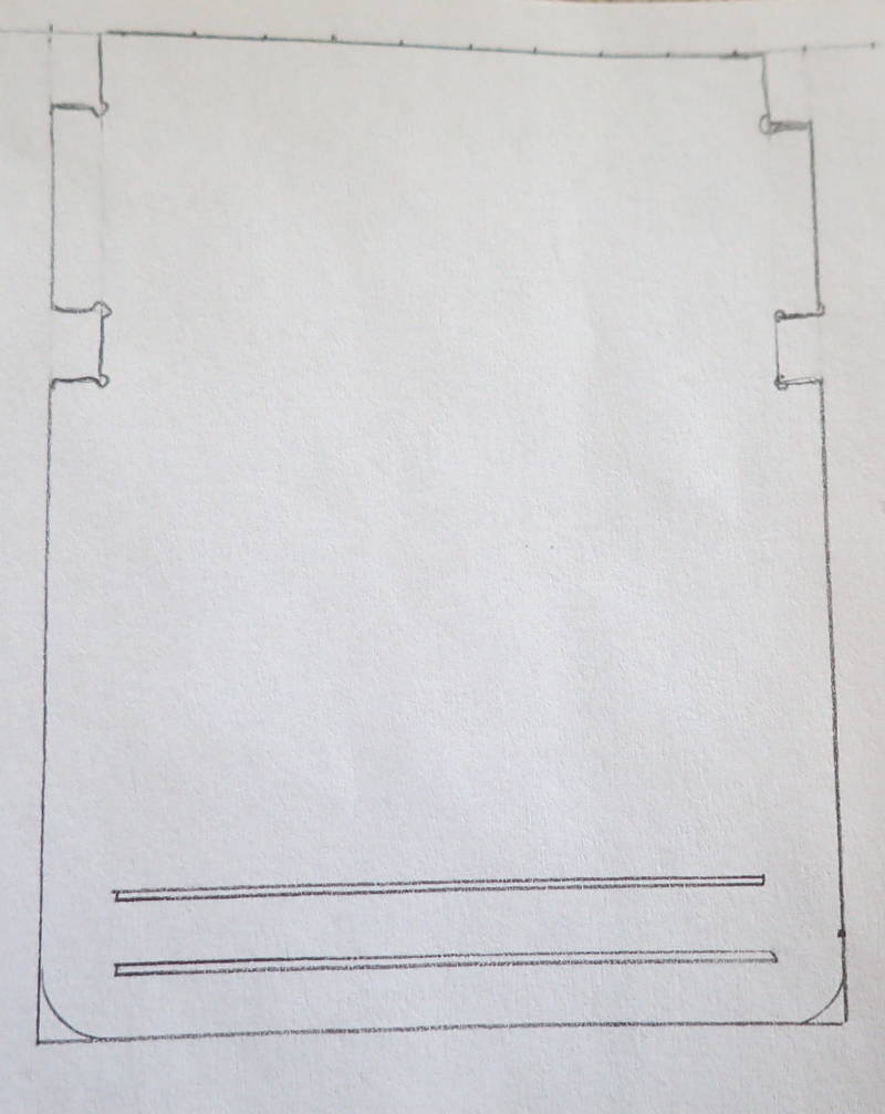
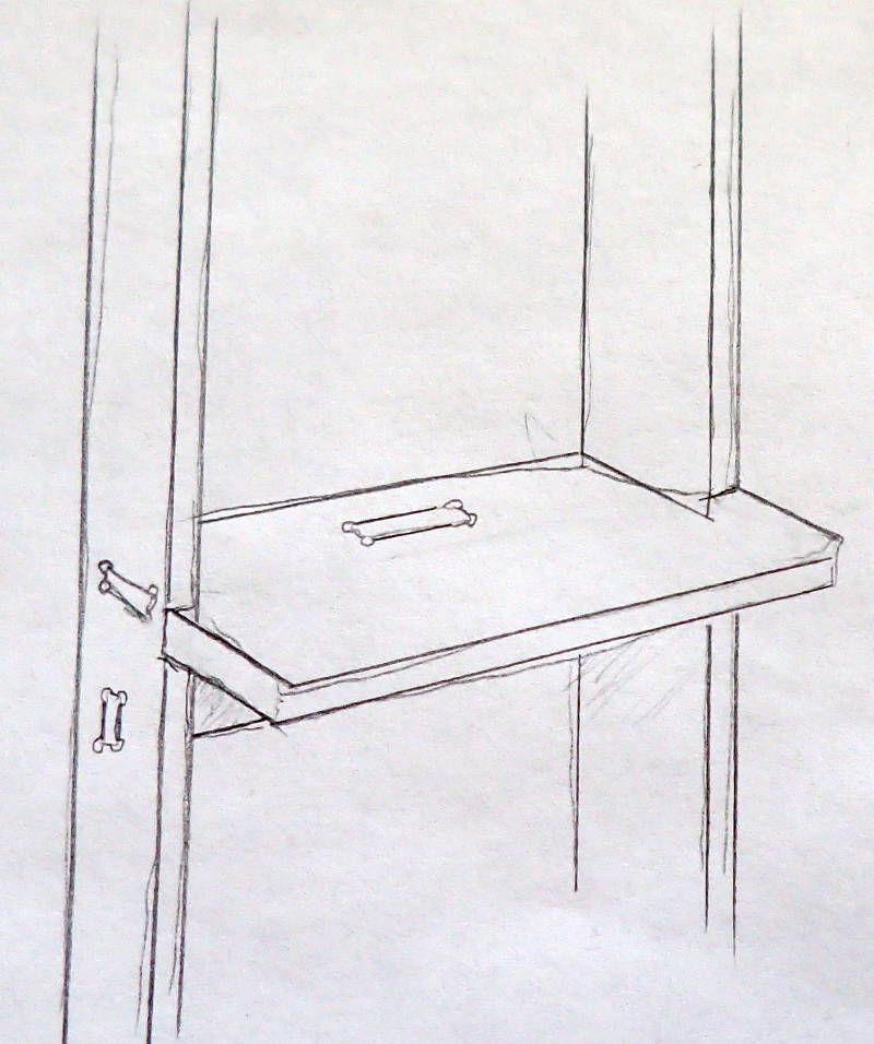
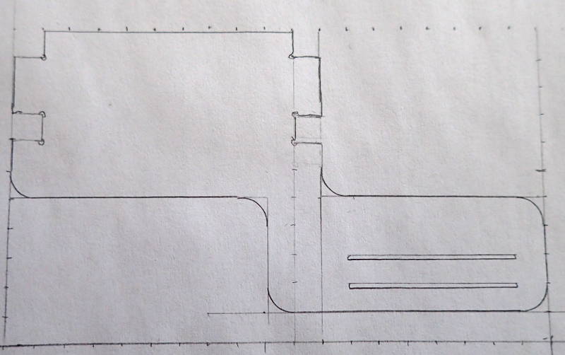
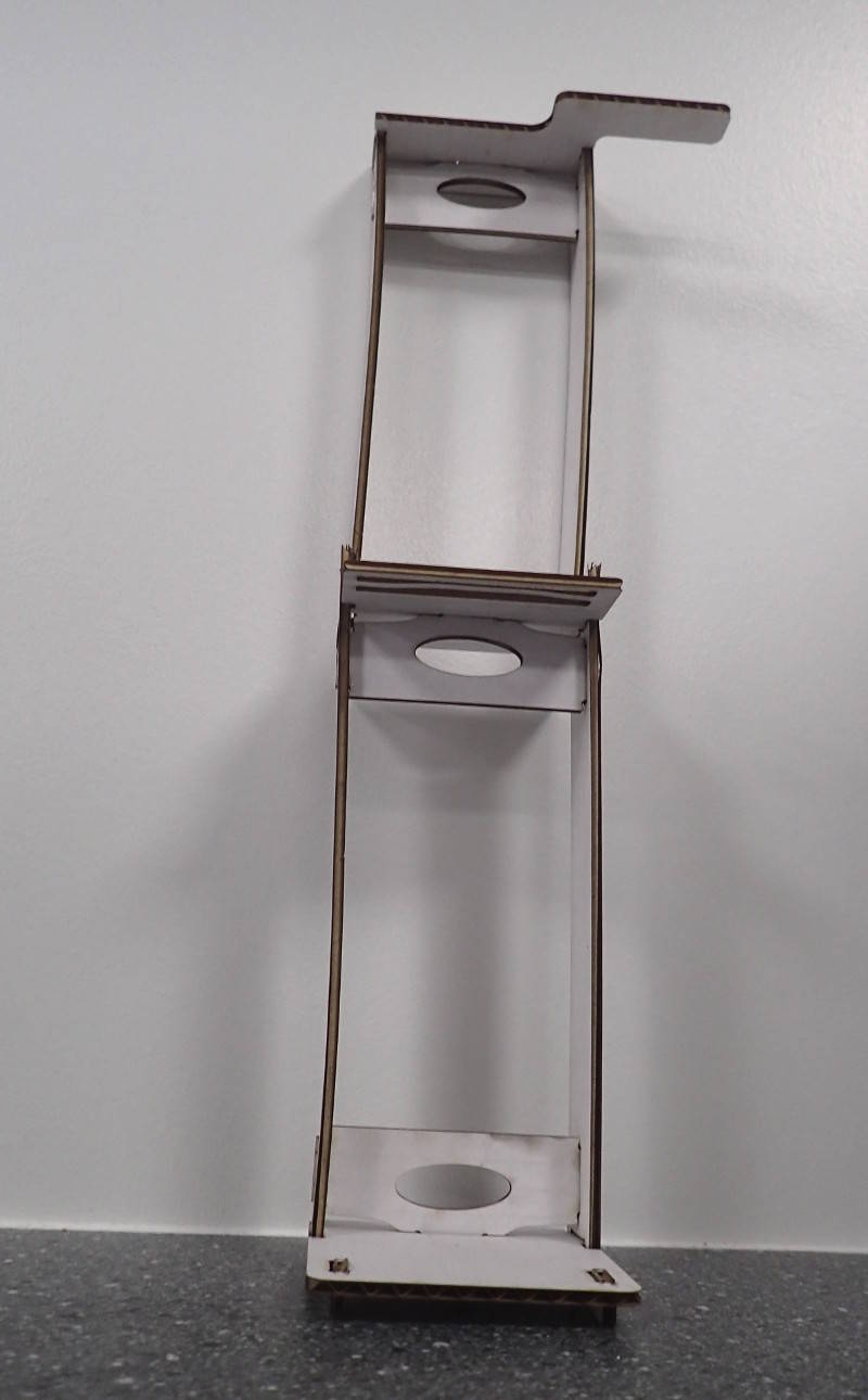
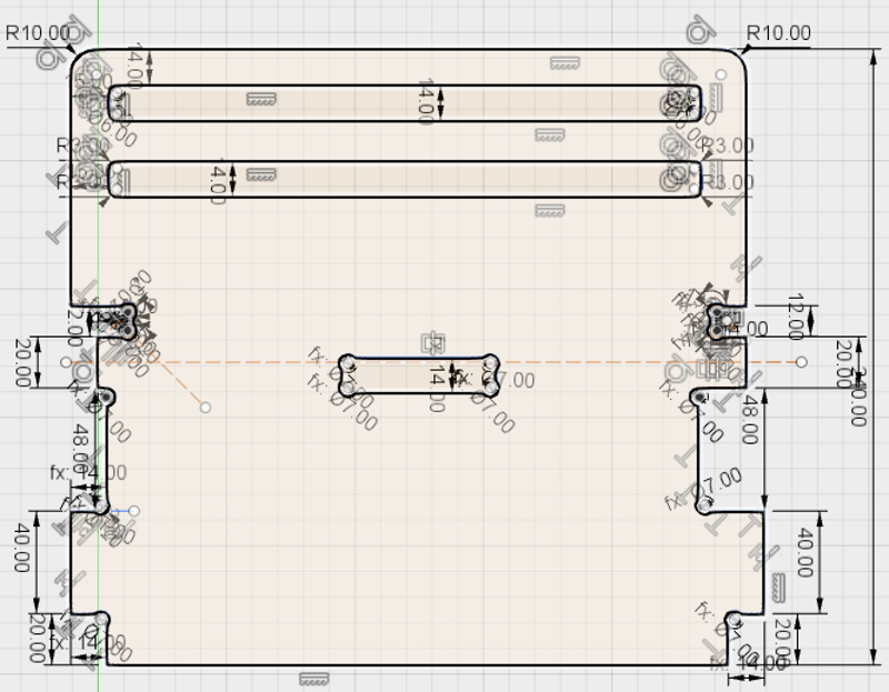
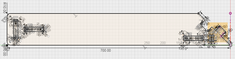
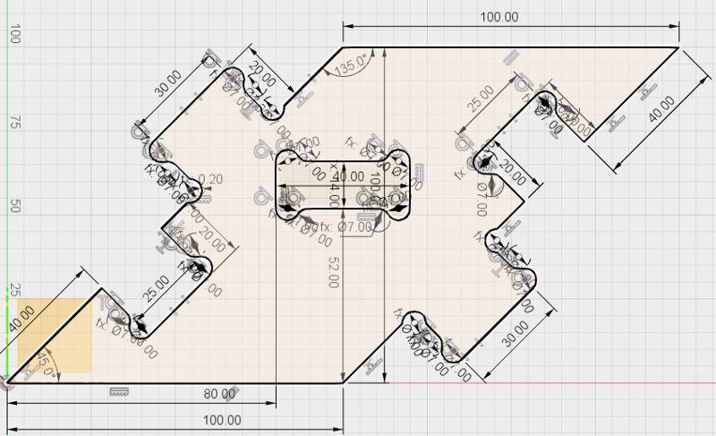
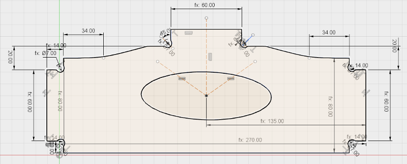
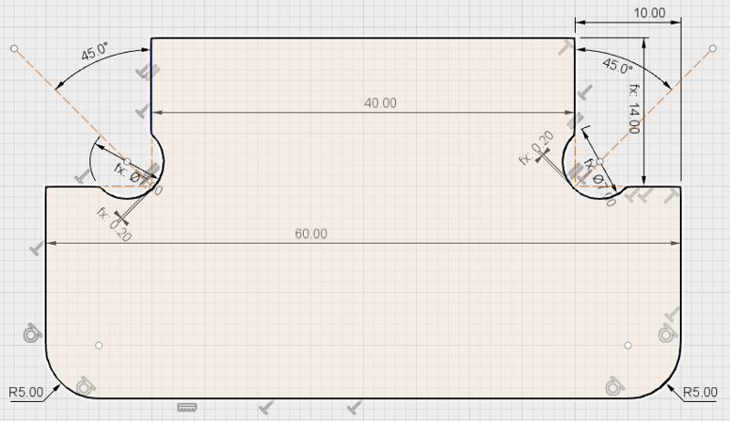
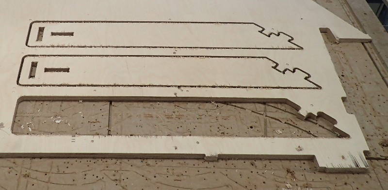
My assignment for the computer controlled machining week is a ladder to help some cats jump through a window. It has a couple of steps stiffened with brackets and a dogleg joint in the middle where it has to clear a window sill. I designed it on paper and modelled it in Fusion 360, which is proving to be quite a challenge and will take more than the one week to finish, as Fusion is an unforgiving adversary to the novice. Fusion has a CAM function, but I chose to export the various parts as PDFs and open them with V carve to send to the ShopBot.
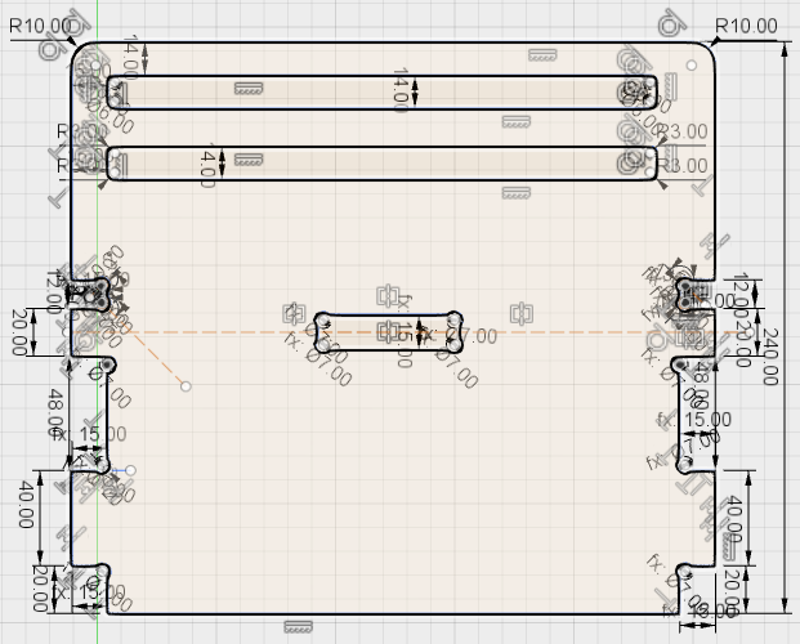
.png) Change parameters in 5mm increments. Model can not keep up with large changes all at once.
Change parameters in 5mm increments. Model can not keep up with large changes all at once.
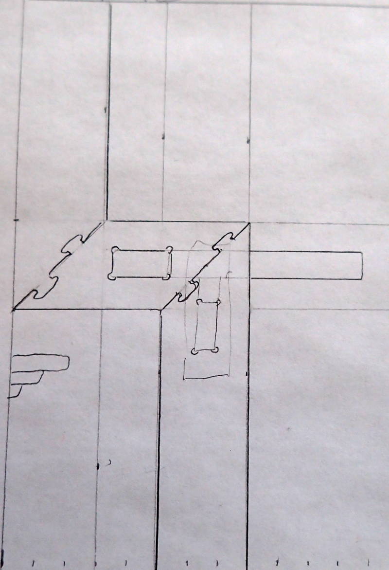
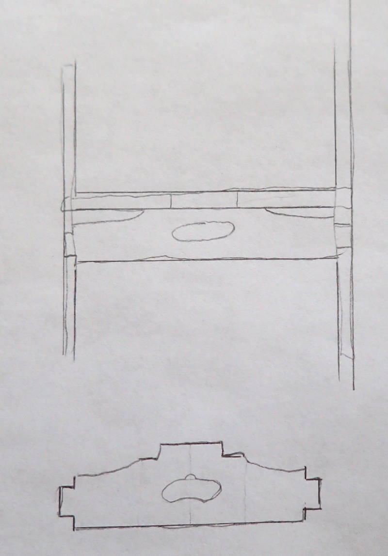
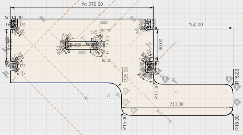
I made the dog bones using the circle/arc tangent technique from NYC CNC's YouTube channel. It was quite laborious to keep those from going to pieces when changing parameters to compensate for variations in the model's height and material thickness, but eventually I managed to get them to resize nicely if it was done in no more than 5mm increments. I could have saved a lot of time and effort by using a dogbone plugin in Fusion 360 or a dogbone fillet in V carve, but I imagined someone downloading this who did not have V carve and wanted to use Fusion 360's CAM function. This was a good exercise in navigating Fusion 360, I still have some way to go in choosing the right order in which to do things.
 Things that make you go Hmmm...
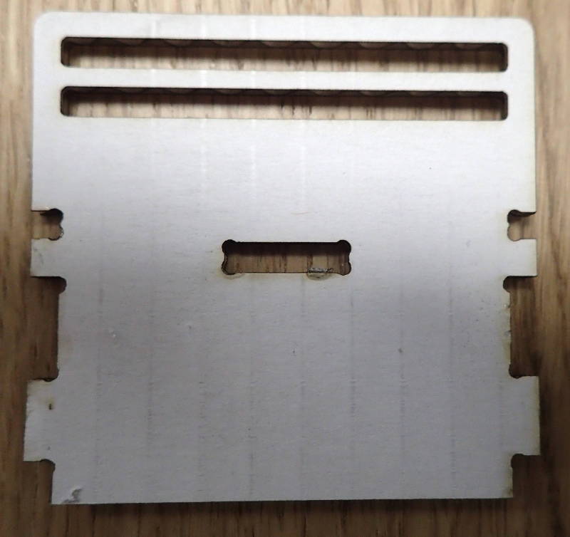
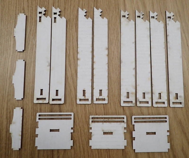
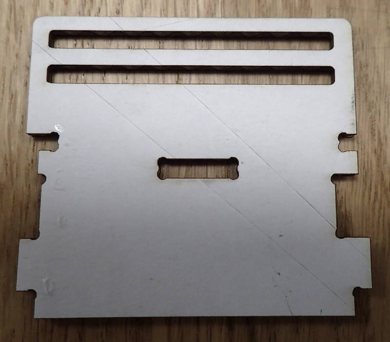
It is a fortunate thing that there are lasercutters where a scale model can be built quickly and cheaply before committing to full size routing on the ShopBot, as the above pieces were all in some way or other misfits and in the case of the step above, multiple iterations were required before I ended up with one where I had not missed some misshapen detail.
Here are the downloadable files for the CatLadder, using 15mm stock. You will still have to calculate tool paths for the Shop Bot with V carve
Snafu edition. Can you spot the mistakes..?
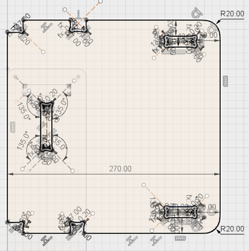
This model has an error. I can not fix it. Anything I try brings up a message that the sketch is over constrained.
I went and redid the model, using a different kind of constraint on the dogbone corners, so the current downloadable files should be free of those errors.
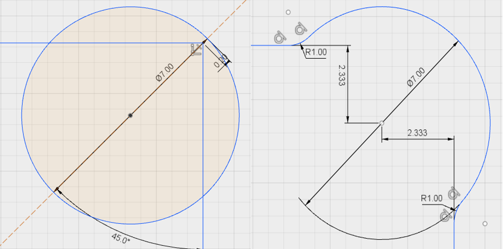
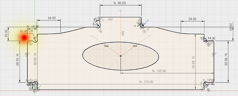
In Fusion 360, I placed a line diagonally in the corner and pressed X to make it a construction line. I made it coincident with the corner and at a 45 degree angle to it. I then pressed C to make a center diameter circle centered on the construction line. In my case the circle was 7mm, to accommodate the bit I would be using. I pressed D and rightclicked and chose Pick circle/arc tangent. I clicked the diameter of the circle and the corner point and made the difference 0.2mm. Now I pressed T and got rid of everything that did not look like a corner with a dog bone, including the construction line. To make the transition from the side to the circle less severe, i chose fillet from the sketch menu and put a 1mm round corner there. Finally I put 2.333mm constraints between the sides and the corner. Now, no matter how I mess with the dimensions, the dog bones seem to keep their integrity.
But I digress; here is the rest.
 Better be safe than sorry.
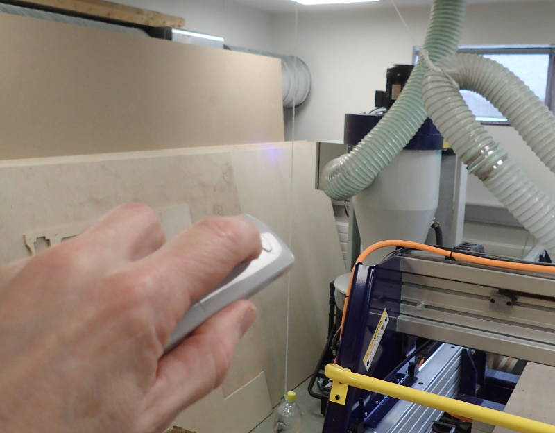 Starting the dust extraction system before beginning cut.
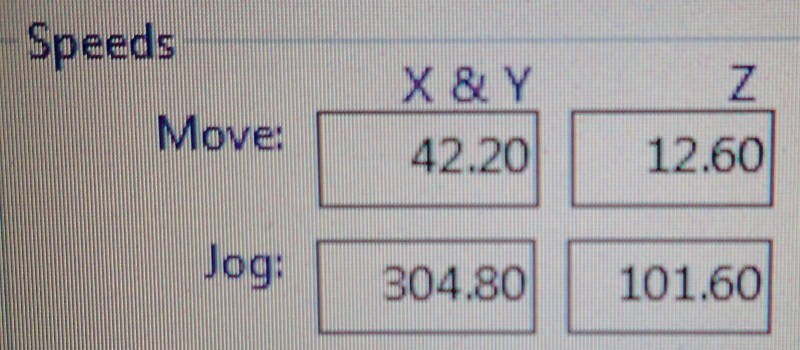 Those feeds are good for cutting in plywood.
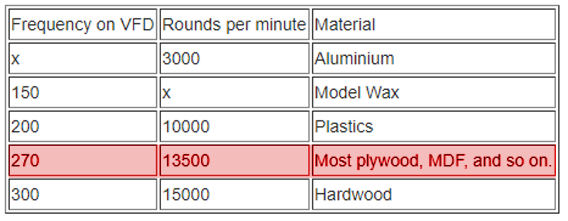 This spindle speed is suggested on the Fablab wiki Shopbot tutorial page.
 I used a 1/4 in. upcutting bit, I would have preferred a straight cutting one, but we could not find it and I had to finish milling the model that day.
 There was some tearout on the upper surface.
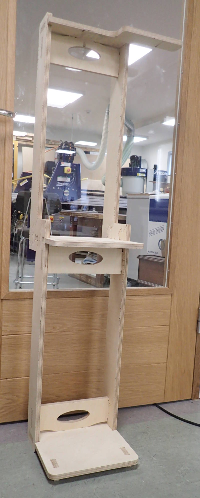
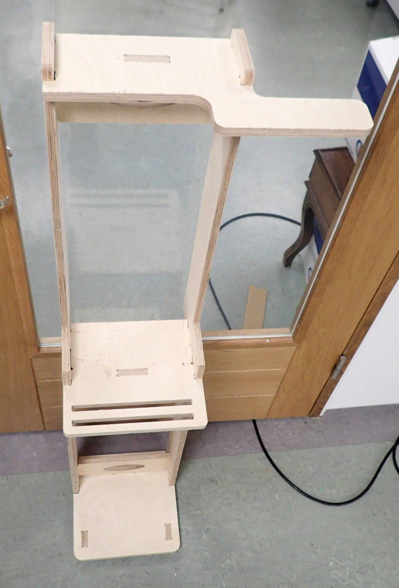
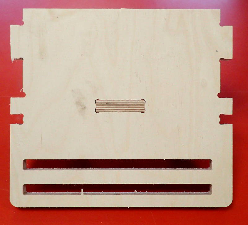 The model ended up with tight tolerances and could be assembled without using glue.
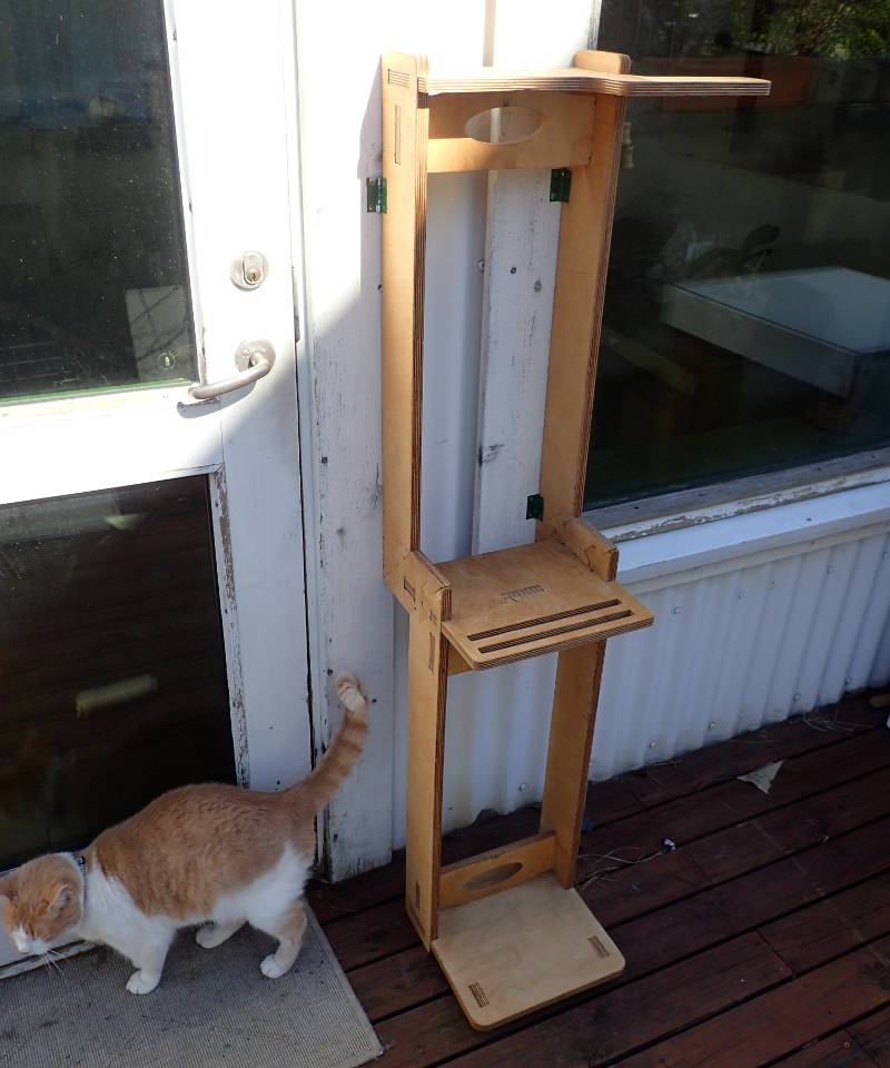
Cat remains resolutely unimpressed.
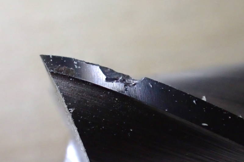 I rushed too much and hit a screw, chipping the bit.
When I was milling the three CatLadderBracket elements, instead of making an initial cutting plan with three of them on it, I only had the one and moved the ShopBot's gantry to a new start position for each additional one, as I was using a plywood sheet that was already cut up from another project and I wanted to use as much of it as possible. In the effort to utilize the last available centimetre, I overlooked one of the screws that held down the plywood sheet and which was well clear of the original cutting plan. Always try to incorporate all the copies of multiple elements on the original cutting plan to avoid such collisions.