Final Project - Glass Break detector
Designing PCB
I have used a SPU0414HR5H-SB microphone for sound detector, and it has a good frequency response curve.

And this is the recommended circuit interface to get the max from the microphone.

The manufacture gives a formular to calculate the C1 and R3 from the above image.

I continued designing the PCB for glass break detector using KiCAD.
This is the screenshot for the schematic.

This is the screenshot for Board design.

This is the 3D view of the board designed.

After designing the board I converted those design in rml file.


Then I printed the board and soldered all components.


This is the list of components I used on the glass break design.
| No | component | Pieces | Value |
|---|---|---|---|
| 1 | ATmega328p | 1 | |
| 2 | nRF24L01 module | 1 | |
| 3 | Microphone | 1 | SPU0414HR5H-SB |
| 4 | RGB LED | 3 | |
| 5 | 5v LDO | 1 | LD1117S50 |
| 6 | Zener Diode | 1 | |
| 7 | Resistor | 1 | 5K |
| 8 | Capacitor | 2 | 100uF |
Designing enclosure
I first measured the size of the board (length x width) and it was (61.58x41.43 mm). From there I add some torelent and made the out size of the enclosure 66x46x20 mm.

Then I inserted a smaller cube of 61x41x18 inside the main cube and made a cut of two shapes.

I inserted a cone which will help to create the inner curve looking on the design.

I inserted another cone and made a cut where I inserted the first cone and the made a small hole where sound will enter from.

On the circuit I made there are three RGB LEDs for displaying the state of the detector, to make them visible I disigned a circular hole on the enclosure where the light will pass through.


After making the hole one part was hanging so I had to add some support to connect it to the remaining part.

After completing the top part of the enclosure I had to design the bottom part for closing the enclosure.
I started with a cube of 66x46x4.

I added another part which helps in interlocking the top part and the bottom part.

Then I made a pocket in the bottom part.

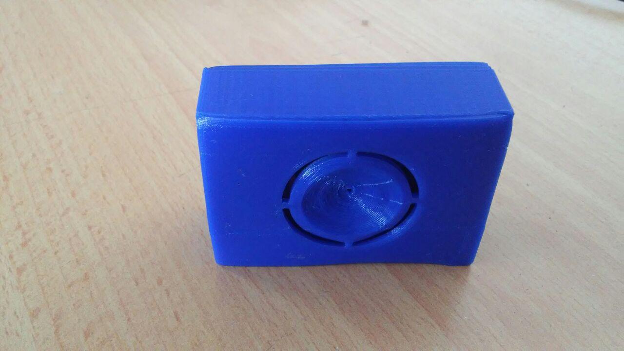
This is the printed enclosure.
Files used
This is the file used of designing the board:
![]()