Inputs Devices
Assignement
- Add a sensor to a microcontroller board that I have designed and read it.
Designing Board
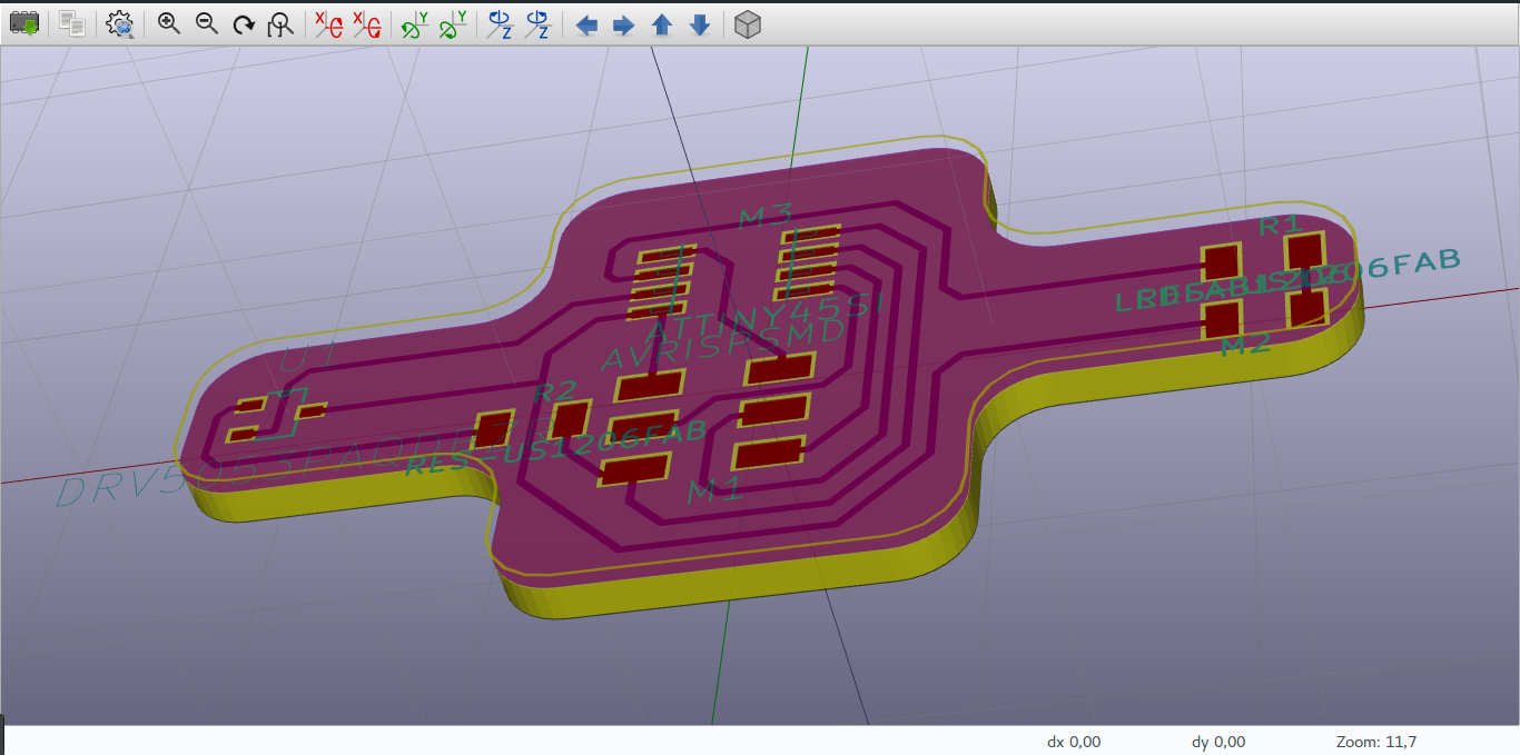
In this assignement I will modify the board I made in week 7 and add an input(sensor) and read the data of that input device.
In modifying the week 7 work, I removed the push button and replaced it with a hall effect sensor for sensing magnetic field around.
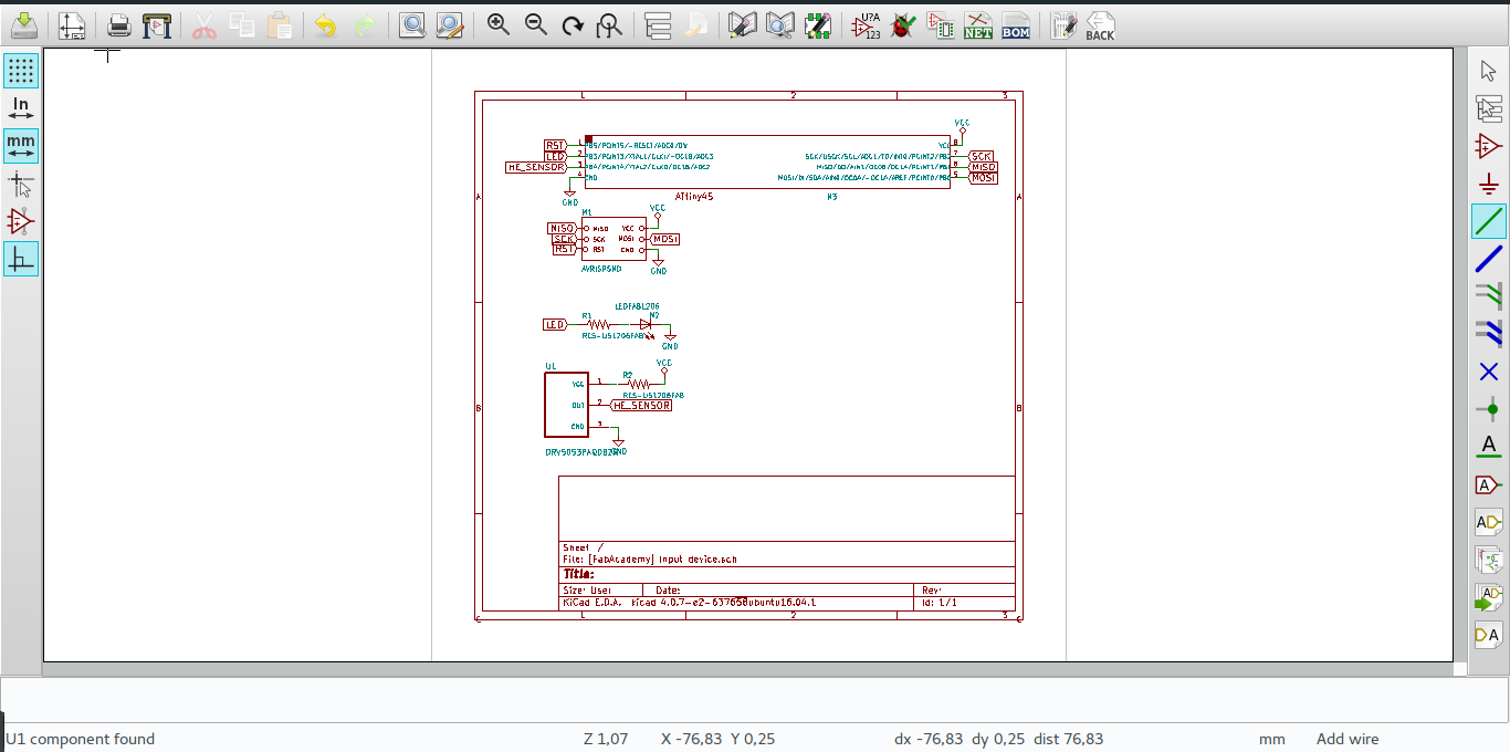
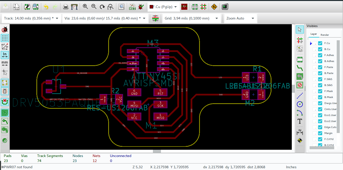
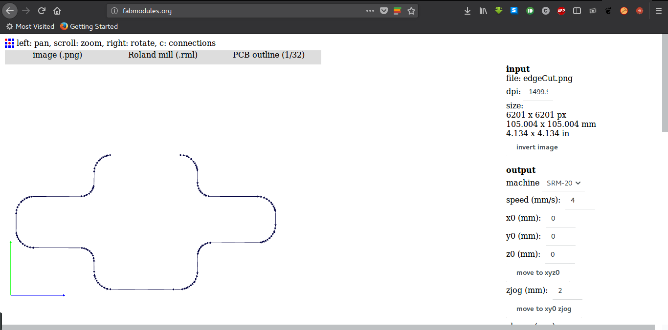
After desinging I generated SVG file which I converted to PNG through Gimp.
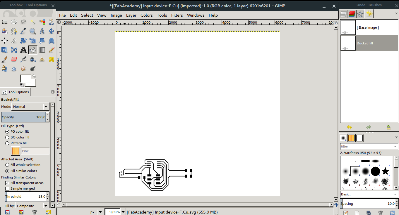
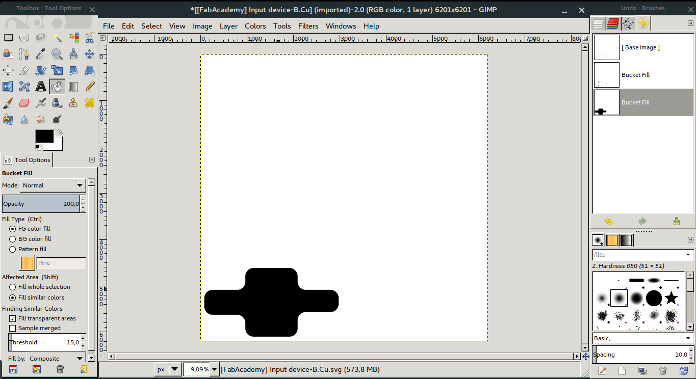
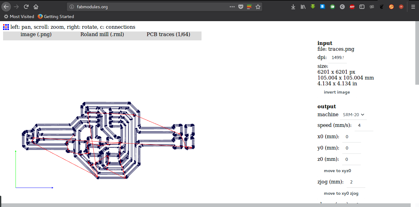
I used the PNG files to create RML file through Fabmodules.
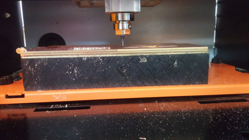
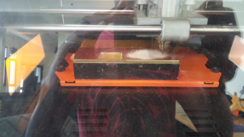
Printing the Board
I first setted the origin cordinates for my board and used the RML file I generated to print and cut my circuit.
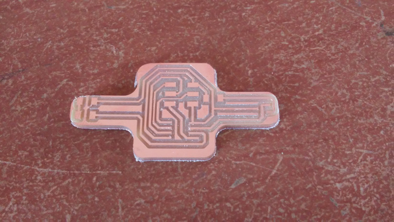
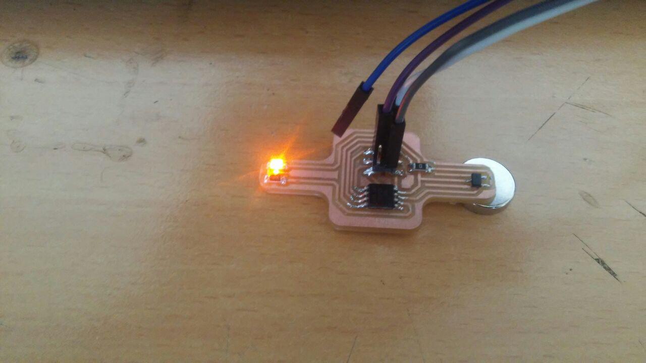
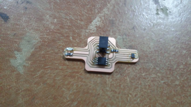
After printing the board I soldered all the component on the board.
Programming
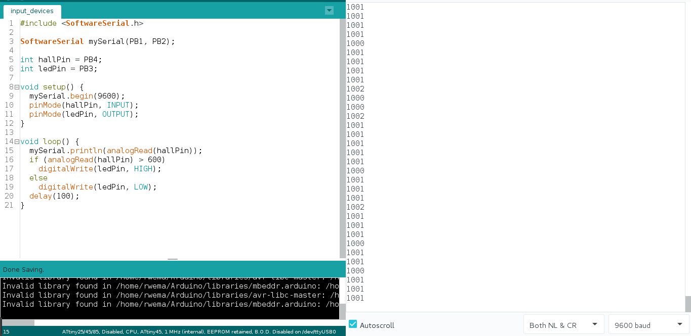
I used Arduino IDE to program my board.
#include <SoftwareSerial.h>
SoftwareSerial mySerial(PB1, PB2);

int hallPin = PB4;
int LEDpin = PB3;

void setup(){
	mySerial.begin(9600);
    pinMode(hallPin, INPUT);
    pinMode(LEDpin, OUTPUT);

}

void loop(){
	mySerial.println(analogRead(hallPin));
	if (analogRead(hallPin) > 600)
		digitalWrite(ledPin, HIGH);
	else
		digitalWrite(ledPin, LOW);
	delay(100);
}
I used this program to check different sides of a magnet. The north pole of the magnet will turn ON the LED and the south pole with turn OFF the LED.