Output Devices
Assignment
- Add an output device to a microcontroller.
- Program it to do something.
Adding an output device
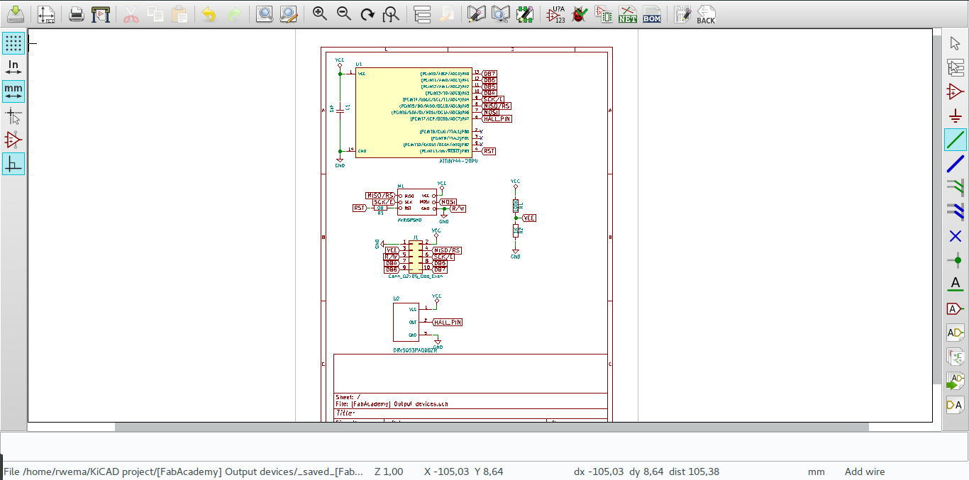
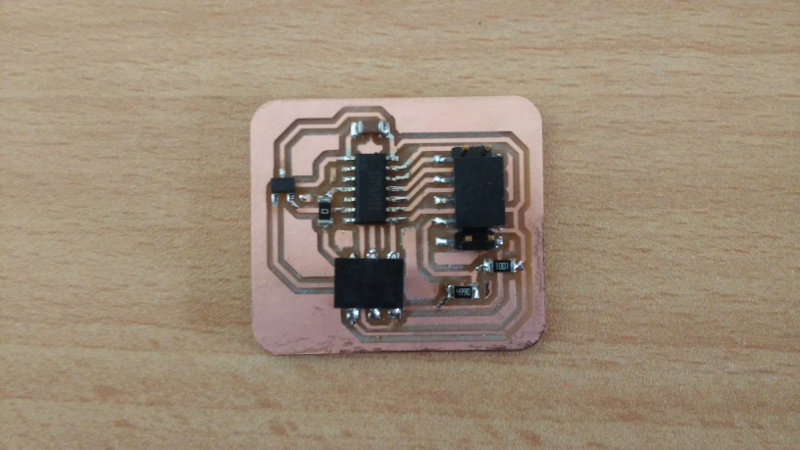
In this assignment I choosed to work with an LCD display an output device, I designed an LCD cicruit using an ATtiny44A microcontrolller. I choosed to work with ATtiny44A as it has many pins compared to ATtiny45.
I designed my cicruit using KiCAD software, below are screenshot take of the designs.
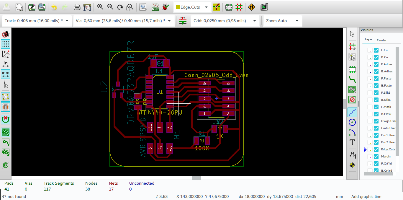
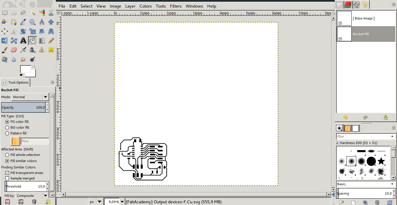
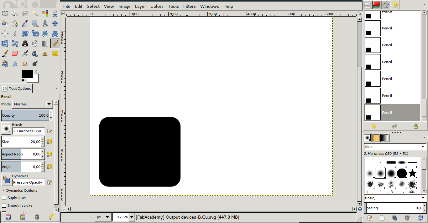
After creating a board in KiCAD I generate svg file which I convert to png to increase its dpi(inch/px), I use gimp to create those png image.
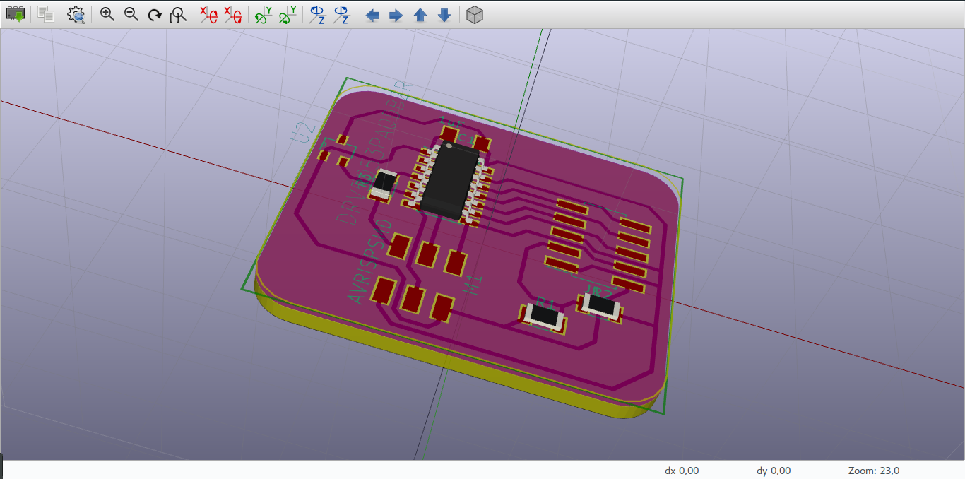
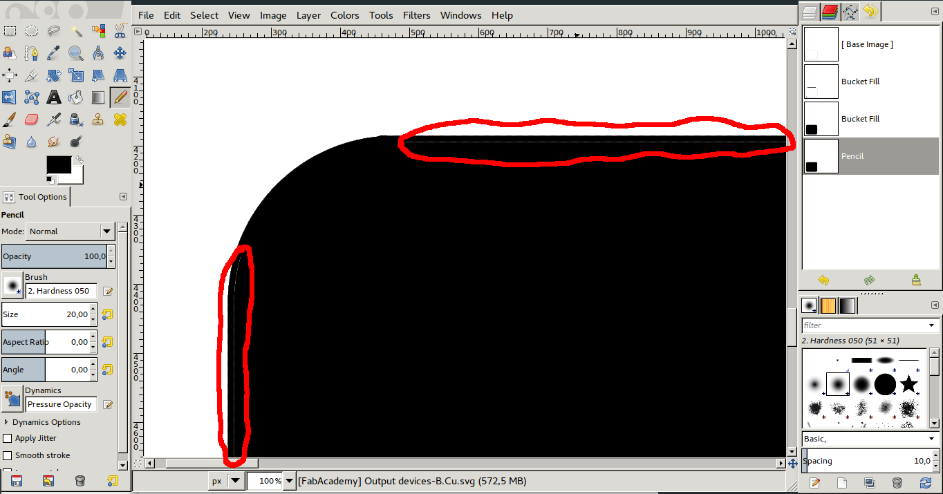
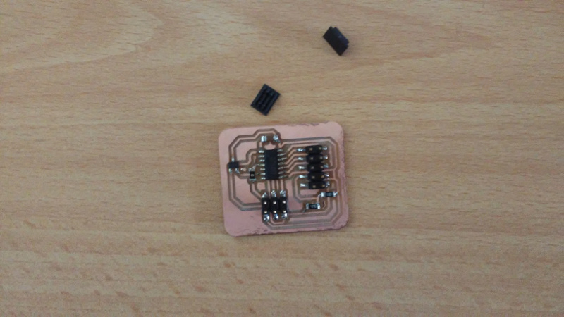
On the outline image there are some details need to be payed attention on since they can ruin you hole board.
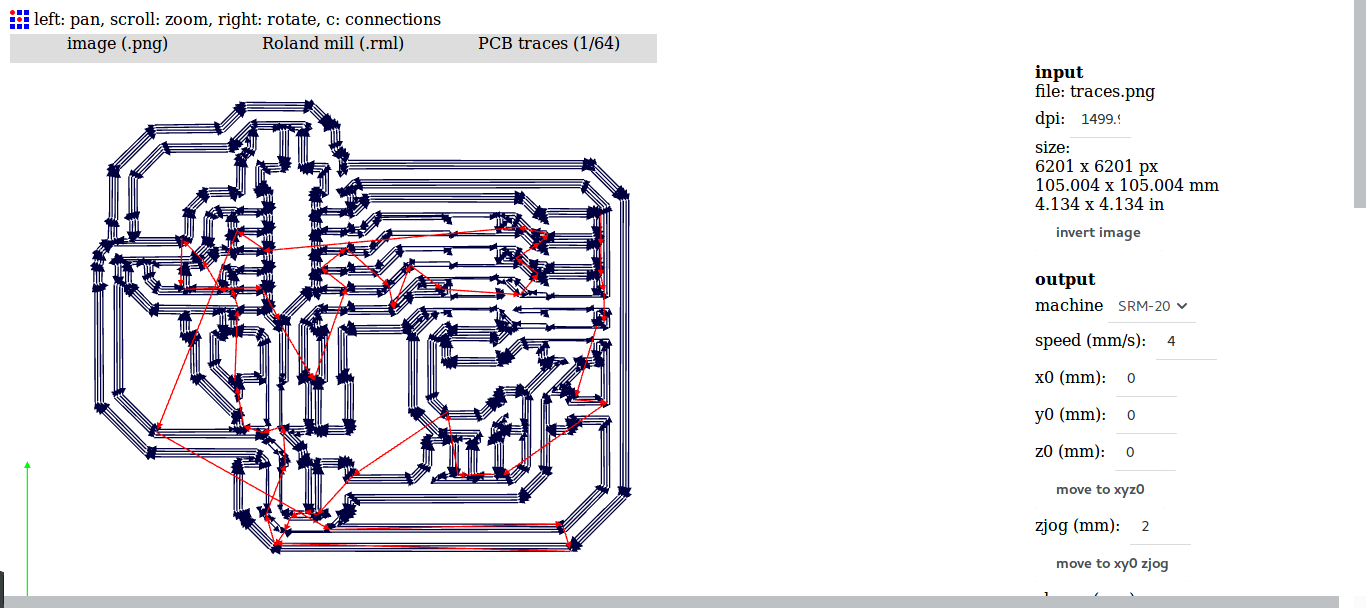
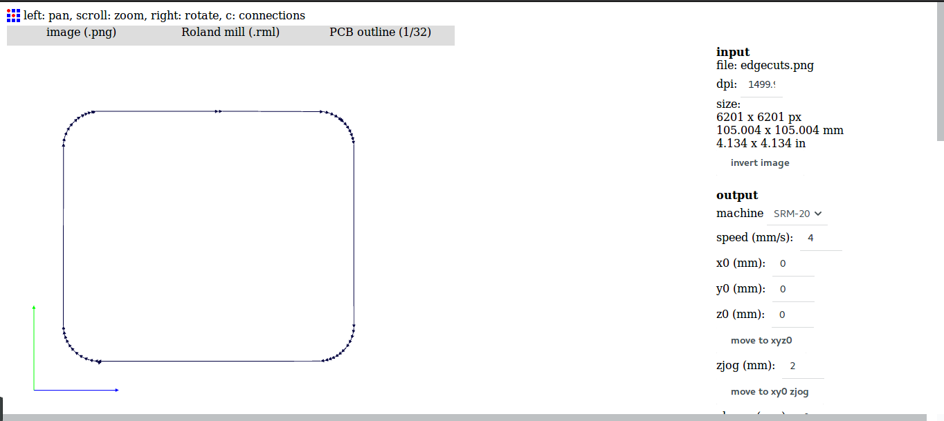
When I have the final png file, I convert them into rml file for the roland to mill them on the board.
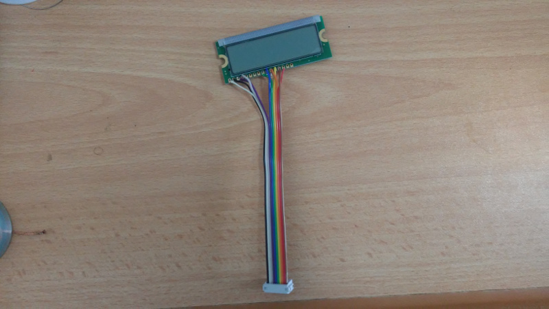
Now that rml files are generated I can mill the PCB, and solder all the components in their place also attach the LCD.
Programming
The next step is to program the microcontroller to display something on the LCD attached. I have first test the connection of the LCD and write a helloworld program in arduino IDE connected to an arduino Nano, and I was able to get it running.
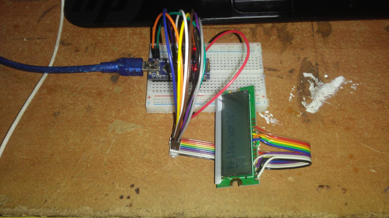
This is the program I used to test the LCD.
#include <LiquidCrystal.h>
LiquidCrystal lcd(12, 11, 5, 4, 3, 2, 1);

int PWMpin = 6;

void setup(){
     lcd.beging(16, 2);
     lcd.print("hello, world");

     pinMode(PWMpin, OUTPUT);
     analogWrite(PWMpin, 123);
}

void loop(){
     lcd.setCursor(0, 1);
     lcd.print(millis() / 1000);
}
After testing the LCD with an arduino, I programed the board to display readings from the Hall effect sensor in a human understandable form.
#include <LiquidCrystal.h>

LiquidCrystal lcd(5, 4, 3, 2, 1, 0);

int hallSensor_pin = 7;
int magnetValue;

void setup(){
	pinMode(PA1, OUTPUT);
	pinMode(PA3, OUTPUT);

     lcd.begin(16, 2);

     lcd.setCursor(1, 0);
     lcd.print("Reading Magnet");
     lcd.setCursor(0, 1);
     lcd.print("N");
     lcd.setCursor(15, 1);
     lcd.print("S");
}

void loop(){
     magnetValue = analogRead(hallSensor_pin);

     if ((magnetValue < 515 ) && (magnetValue >= 500)){
     	 lcd.setCursor(6, 1);
     	 lcd.print(" ||      ");
     }
     reading_N(magnetValue);
     reading_S(magnetValue);
}

void reading_N(int magValue){
	if ((magValue < 500) && (magValue >= 424)){
		lcd.setCursor(1, 1);
		lcd.print("     |");
	}
	if ((magValue < 424) && (magValue >= 339)){
		lcd.setCursor(1, 1);
		lcd.print("    |");
	}
	if ((magValue < 339) && (magValue >= 255)){
		lcd.setCursor(1, 1);
		lcd.print("   |");
	}
	if ((magValue < 255) && (magValue >= 171)){
		lcd.setCursor(1, 1);
		lcd.print("  |");
	}
	if ((magValue < 171) && (magValue >= 87)){
		lcd.setCursor(1, 1);
		lcd.print(" |");
	}
	if ((magValue < 87) && (magValue >= 0)){
		lcd.setCursor(1, 1);
		lcd.print("|");
	}
}

void reading_S(int magValue){
	if ((magValue > 516) && (magValue <= 585)){
		lcd.setCursor(9, 1);
		lcd.print("|     ");
	}
	if ((magValue > 586) && (magValue <= 658)){
		lcd.setCursor(10, 1);
		lcd.print("|    ");
	}
	if ((magValue > 659) && (magValue <= 731)){
		lcd.setCursor(11, 1);
		lcd.print("|   ");
	}
	if ((magValue > 732) && (magValue <= 804)){
		lcd.setCursor(12, 1);
		lcd.print("|  ");
	}
	if ((magValue > 805) && (magValue <= 950)){
		lcd.setCursor(13, 1);
		lcd.print("| ");
	}
	if ((magValue > 951) && (magValue <= 1023)){
		lcd.setCursor(14, 1);
		lcd.print("|");
	}
}
This is a short video showing the LCD working.