Embedded Networking and Communications
Work to be done
- Design and Build a wired/wireless network connecting at least two processors.
Designing
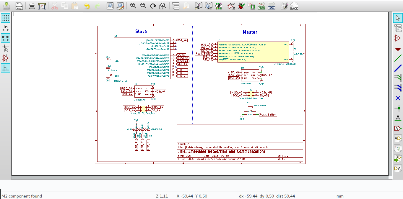
I choosed to work with SPI communication on this assignment.
I used to different processor to communicate, ATtiny44 and ATtiny45. In designing these boards I used one schematic to easy the process.
On the master part I used an ATtiny45 with a push button to controll the RGB led on the slave side.
The slave part I used an ATtiny44 with an RGB led which will display different colours according to the signal sent from the master by the push button, the slave will give a feedback to the master after displaying a specific colour.
I started designing the two boards on the same schematic design, it was the first time I was trying this.
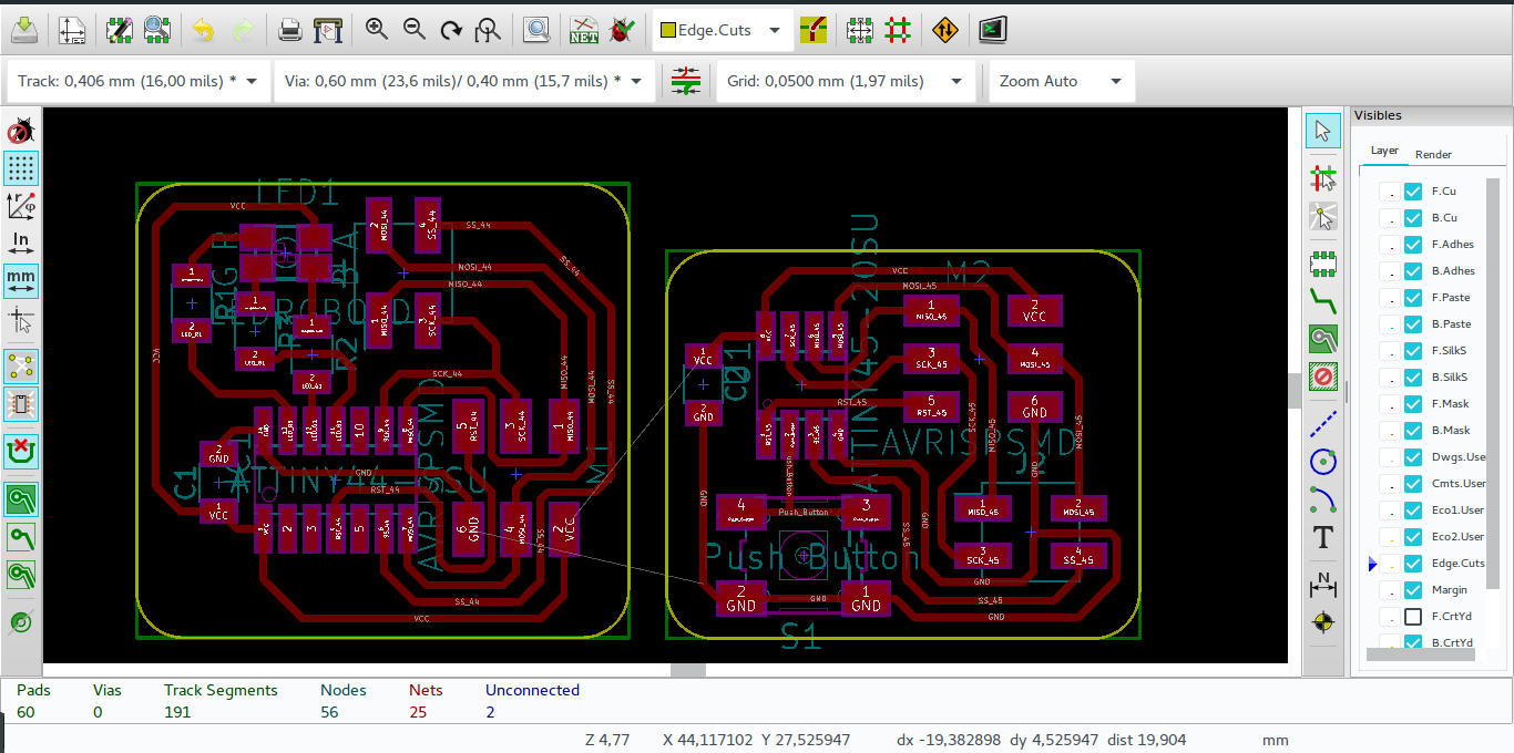
Moving to the board layout was easy to make those two boards, but the issue was that the both board had the same power connection, which resulted in two ratsnest left unconnected.
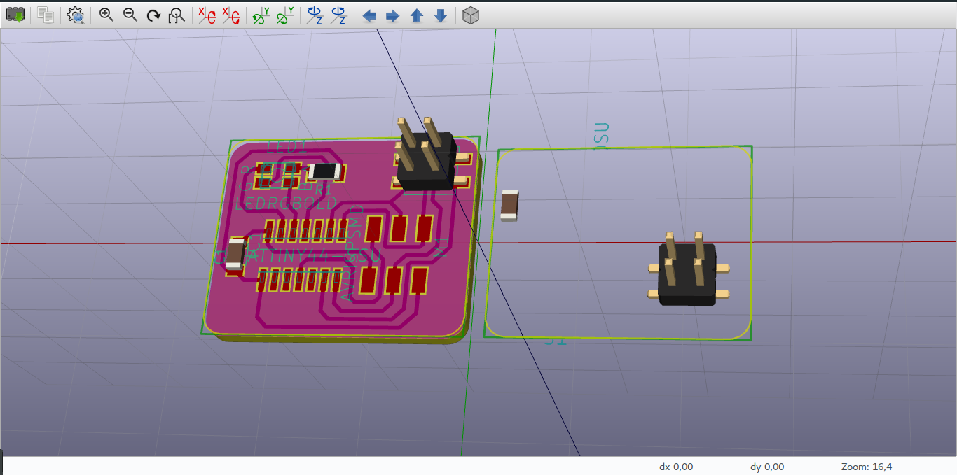
For the 3D view, it was not quit well since parts of the second board(master board) was not visible. But this part is not necessary its just for viewing the final look of the design.
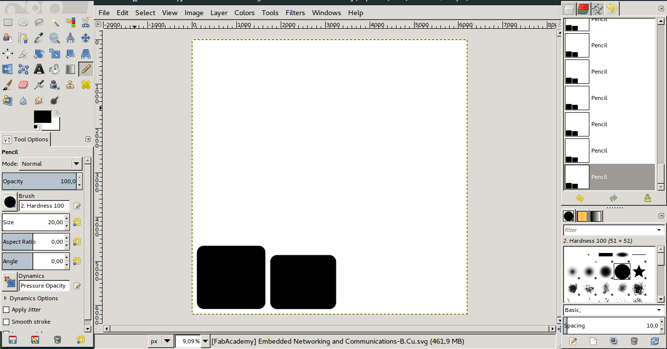
After designing I converted images generated by KiCAD into png since it generates svg image.
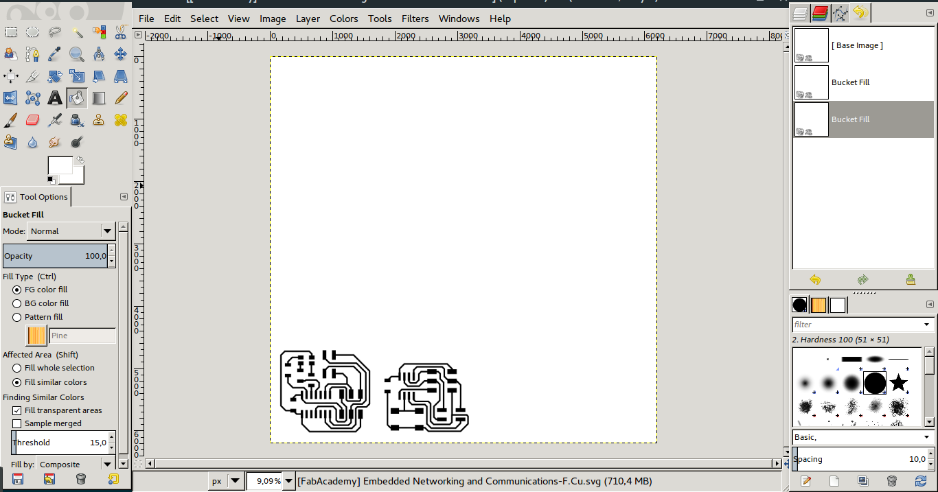
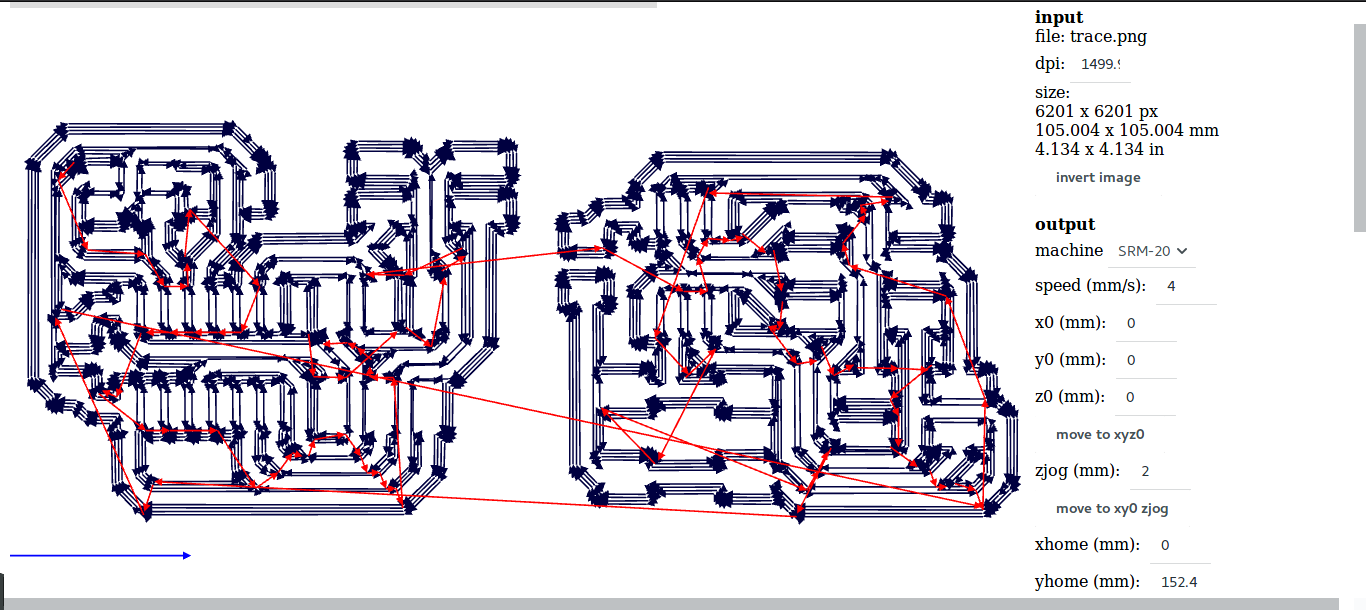
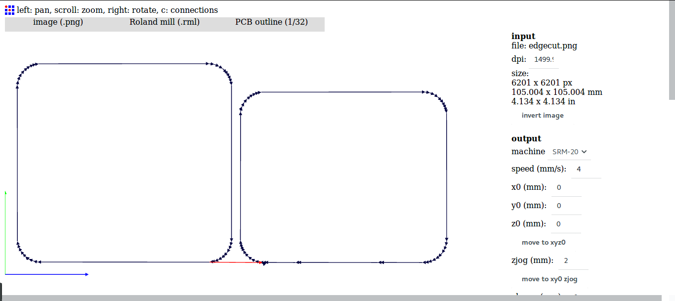
After that I used fabmodules to generated rml files to be used in the monofab machine.
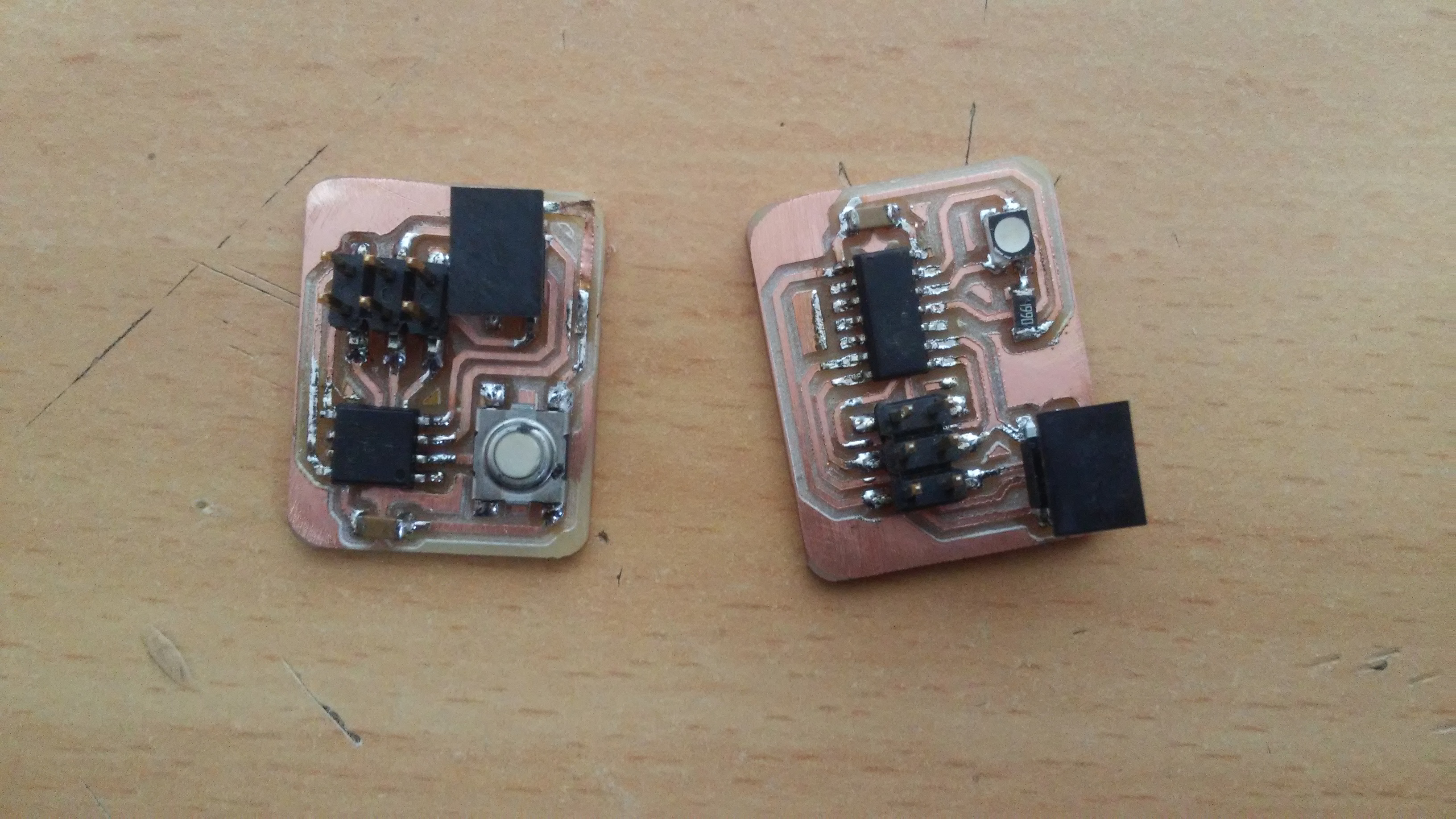
Building
I printed the board that I designed and soldered all components.
This is the list of components used:
Master components
| No | Component | Piece(s) | Value |
|---|---|---|---|
| 1 | ATtiny45 | 1 | |
| 2 | Push button | 1 | |
| 3 | AVR ISP | 1 | |
| 4 | Capacitor | 1 | 1uF |
| 5 | 2x2 connector | 1 |
Slave components
| No | Component | Pieces(s) | Value |
|---|---|---|---|
| 1 | ATtiny44 | 1 | |
| 2 | RGB LED | 1 | |
| 3 | AVR ISP | 1 | |
| 4 | 2x2 connector | 1 | |
| 5 | Resistor | 3 | 500R |
| 6 | Capacitor | 1 | 1uF |
Programming
Master program
#define F_CPU 1000000UL

#include <avr/io.h>
#include <util/delay.h>

#define True     1
#define False    0

#define USI_MOSI      PINB0
#define USI_MISO      PINB1
#define USI_SCK   PINB2
#define USI_SS        PINB4
#define USI_DDR   DDRB
#define USI_PORT      PORTB

void USI_SPI_init(uint8_t mode){
     if(1 == mode){  // Master mode
          USI_DDR |= (1<<USI_MOSI)|(1<<USI_SCK)|(1<<USI_SS);
          USI_PORT |= (1<<USI_SS):
          USI_DDR &= ~(1<<USI_MISO);
          USI_PORT |= (1<<USI_MISO):
          USISR |= (1<<USIOIF);
          USICR |= (1<<USIWM0)|(1<<USICS1)|(1<<CLK)|(1<<USITC);
     }
     else if (0 == mode){    //Slave mode
          USI_DDR &= ~((1<<USI_MISO)|(1<<USI_SCK)|(1<<USI_SS));
          USI_DDR |= (1<<USI_MOSI);
          USI_PORT |= (1<<USI_MISO)|(1<<USI_SCK)|(1<<USI_SS);
          USICR = (1<<USIWM0)|(1<<USIOIE)|(1<<USICS1);
     }
     else { // Signal when wrong mode is selected
          DDRB |= (1<<PINB0);
          PORTB |= (1<<PINB0):
     }
}

void USI_SPI_transfer(uint8_t dataIn){
     USI_PORT &= ~(1<<USI_SS);
     USIDR = dataIn;
     do{
          USICR |= (1<<USIWM0)|(1<<USICS1)|(1<<USICLK)|(1<<USITC);
     }while((USISR & (1<<USIOIF)) == 0);
     USI_PORT |= (1<<USI_SS);
}

uint8_t USI_SPI_receiver(void){
     USISR |= (1<<USIOIF);
     while((USISR & (1<<USIOIF)) == 0);
     return USIDR;
}

int main(){
     DDRB &= ~(1<<PINB3);
     PORTB |= (1<<PINB3);
     USI_SPI_init(1);
     uint8_t count = 0;
     uint8_t colourNum = 0;
     while(True){
          if (bit_is_clear(PINB, 3){
                count += 1;
                if (colourNum > 7)
                     colourNum = 0;
                if (count >= 400){
                     colourNum++;
                     USI_SPI_transfer(colourNum);
                     count =  0;
                }
          }
          _delay_ms(50);
     }
}
Slave program
#define F_CPU 1000000UL

#include <avr/io.h>
#include <avr/iotn44.h>
#include <util/delay.h>

#define True     1
#define False    0

#define USI_MOSI      PINA6
#define USI_MISO      PINA5
#define USI_SCK   PINA4
#define USI_SS        PINA7
#define USI_DDR   DDRA
#define USI_PORT      PORTA

void USI_SPI_init(uint8_t mode){
     if(1 == mode){  // Master mode
          USI_DDR |= (1<<USI_MOSI)|(1<<USI_SCK)|(1<<USI_SS);
          USI_PORT |= (1<<USI_SS):
          USI_DDR &= ~(1<<USI_MISO);
          USI_PORT |= (1<<USI_MISO):
          USISR |= (1<<USIOIF);
          USICR |= (1<<USIWM0)|(1<<USICS1)|(1<<CLK)|(1<<USITC);
     }
     else if (0 == mode){    //Slave mode
          USI_DDR &= ~((1<<USI_MISO)|(1<<USI_SCK)|(1<<USI_SS));
          USI_DDR |= (1<<USI_MOSI);
          USI_PORT |= (1<<USI_MISO)|(1<<USI_SCK)|(1<<USI_SS);
          USICR = (1<<USIWM0)|(1<<USIOIE)|(1<<USICS1);
     }
     else { // Signal when wrong mode is selected
          DDRB |= (1<<PINB0);
          PORTB |= (1<<PINB0):
     }
}

void USI_SPI_transfer(uint8_t dataIn){
     USI_PORT &= ~(1<<USI_SS);
     USIDR = dataIn;
     do{
          USICR |= (1<<USIWM0)|(1<<USICS1)|(1<<USICLK)|(1<<USITC);
     }while((USISR & (1<<USIOIF)) == 0);
     USI_PORT |= (1<<USI_SS);
}

uint8_t USI_SPI_receiver(void){
     USISR |= (1<<USIOIF);
     while((USISR & (1<<USIOIF)) == 0);
     return USIDR;
}

void setColour(uint8_t value){
     if (value == 1){       // white colour
          PORTA &= ~((_BV(PINA0)|_BV(PINA1)|_BV(PINA2));
     }
     else if (value == 2){   //Blue
          PORTA &= ~_BV(PINA0);
          PORTA |= _BV(PINA1)|_BV(PINA2);
     }
     else if (value == 3){   // Green
          PORTA &= ~_BV(PINA1):
          PORTA |= _BV(PINA0)|_BV(PINA2);
     }
     else if (value == 4){   // Red
          PORTA &= ~_BV(PINA2);
          PORTA |= _BV(PINA0)|_BV(PINA1);
     }
     else if (value == 5){   // Yellow
          PORTA &= ~(_BV(PINA1)|_BV(PINA2));
          PORTA |= _BV(PINA0);
     }
     else if (value == 6){   // Pink
          PORTA &= ~(_BV(PINA0)|_BV(PINA1));
          PORTA |= _BV(PINA2);
     }
     else if (value == 7){   // Blue-ish
          PORTA &= ~(_BV(PINA0)|_BV(PINA2));
          PORTA |= _BV(PINA1);
     }
     _delay_ms(1000);
}

int main(){
     DDRA |= (1<<PINA0)|(1<<PINA1)|(1<<PINA2);
     PORTA |= (1<<PINA0)|(1<<PINA1)|(1<<PINA2);
     USI_SPI_init(0);
     uint8_t dataInt = 0;

     while(True){
          dataIn = USI_SPI_receiver():
          setColour(dataIn);
          dataIn = 0;
     }
}
This is a short video of the system.
Files used
![]()