Computer-controlled Cutting
Assignement
- Cut something on the vinylcutter
- Design, lasercut, and document a parametric press-fit construction kit.
Vinylcutter
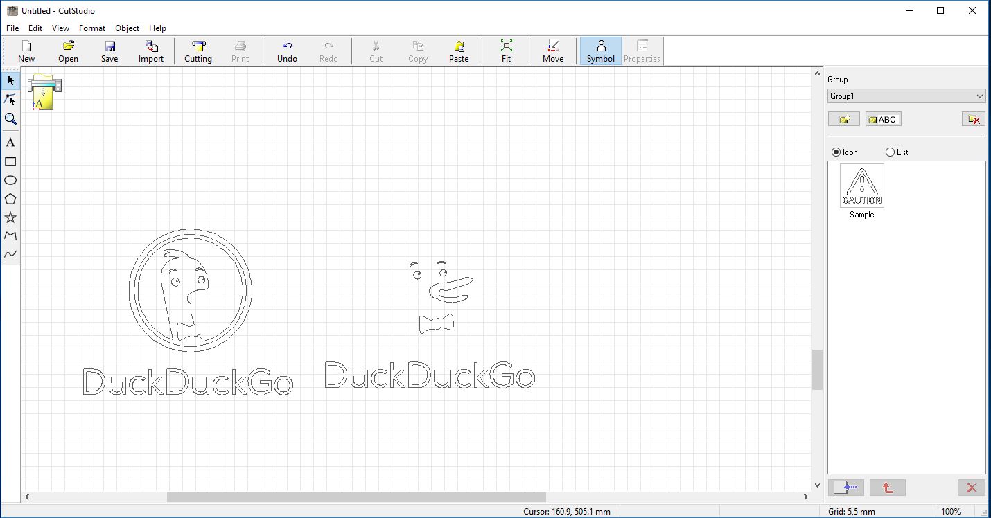
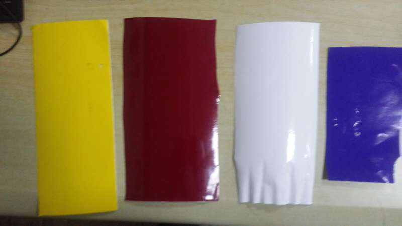
I decide to make some logo for my computer, I choosed to make one for DuckDuckGo search engine and another for Free Software Foundation. But they're not that easy since they have different colours.
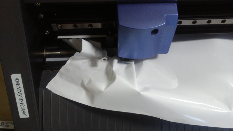
I downloaded duckduckgo logo and change some of its colour for the vinylcutter software to recognise them.
I imported duckduckgo image in vinylcutter software.
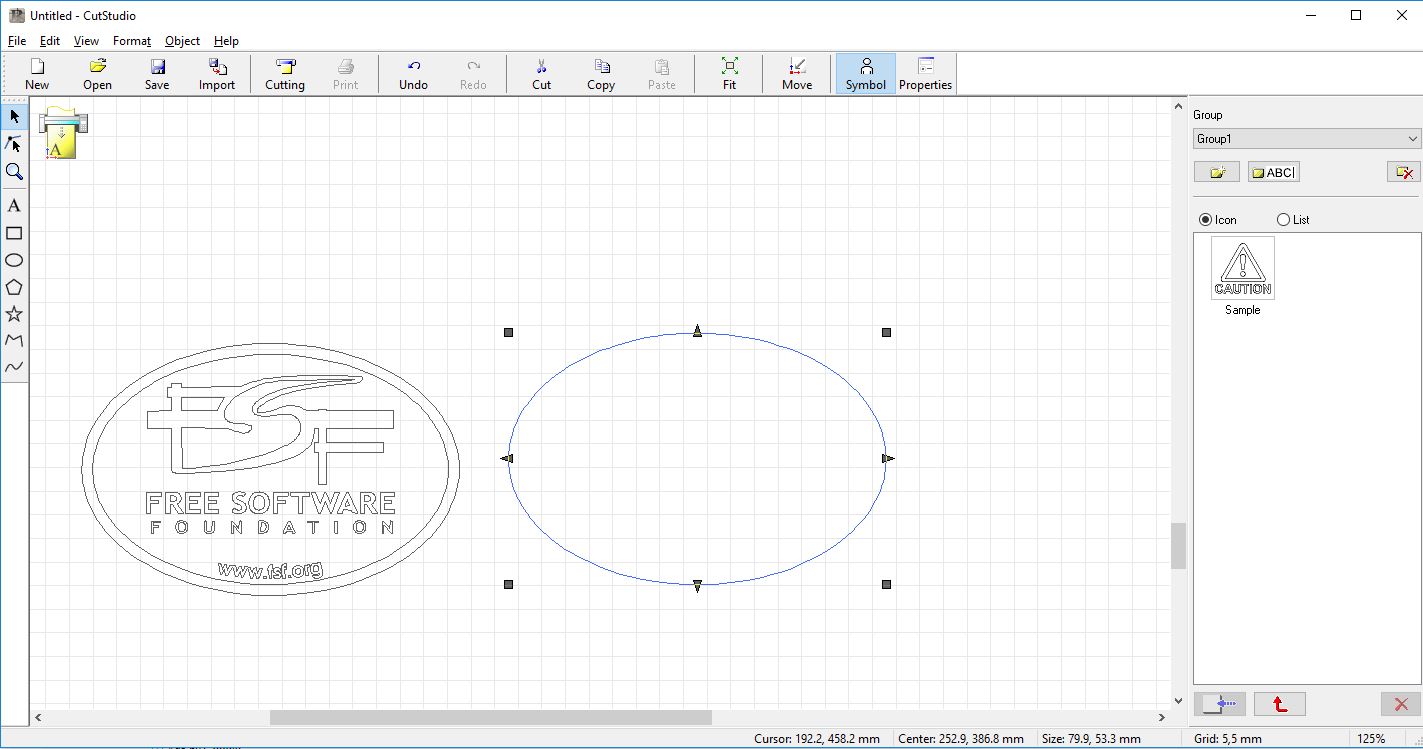
For free software foundation I had the exact colours and the work was straight forward even if I faced some issue with the old blade which did damaged the paper, but it was not a big deal. I replaced the blade and everything was fine.
After the cutting I had to combine different pieces of the logo fo the final logo. It was a challenging task and at the end I enjoyed it.
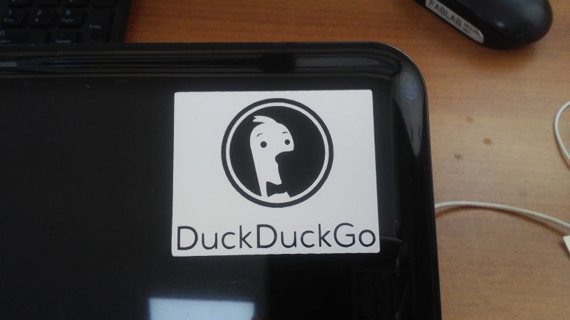
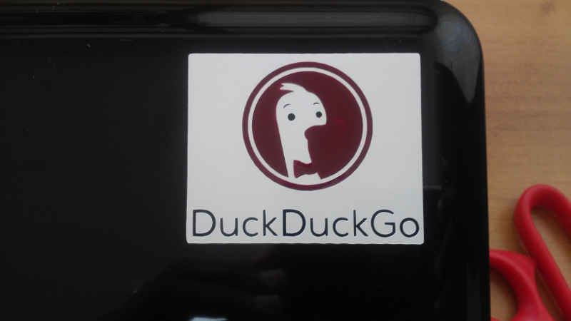

And you can see how beautiful it is. The below image is for FSF logo, also beautiful.
Also for FSF logo I imported in vinylcutter software (cutstudio).

Lasercutter
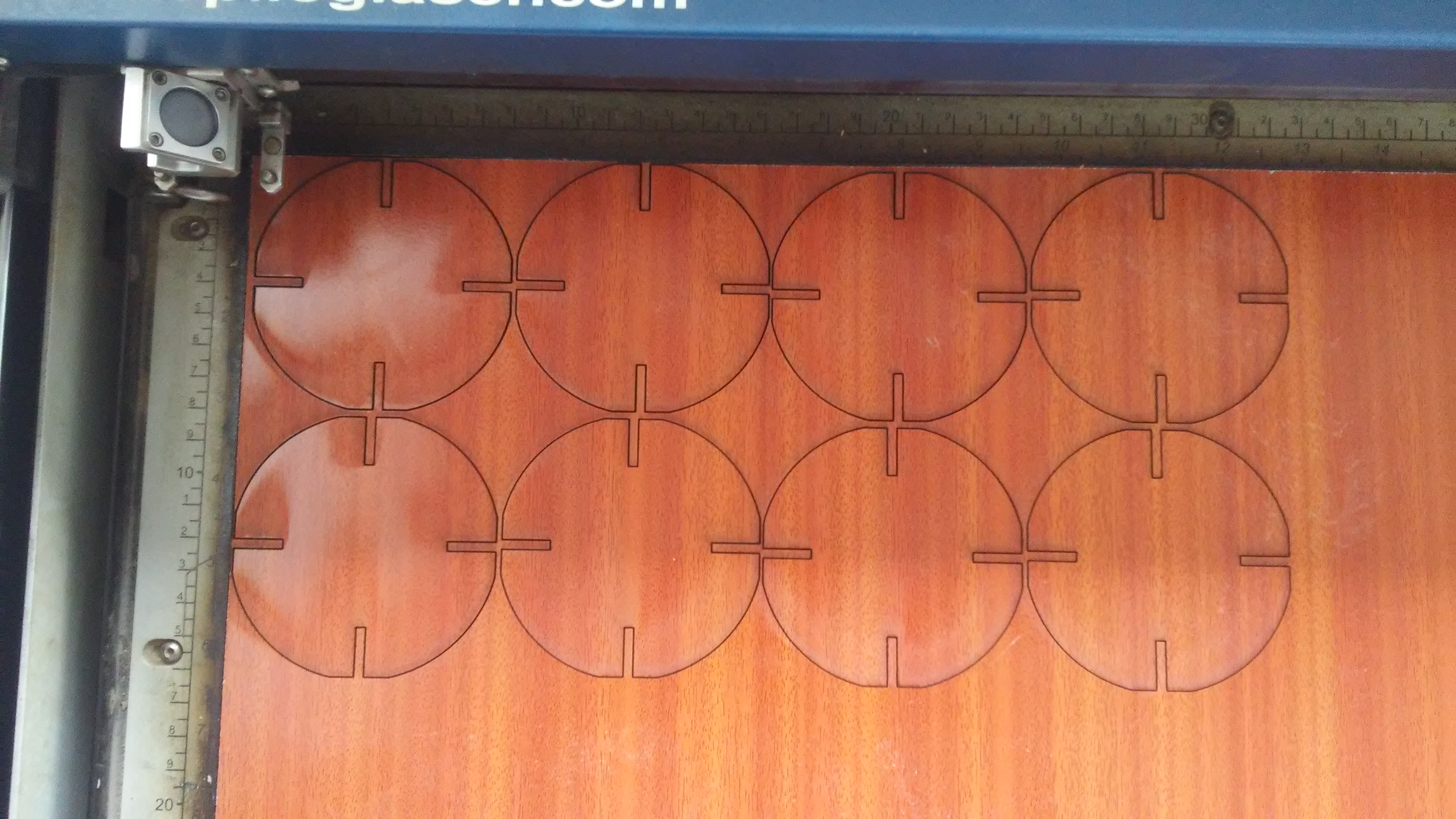
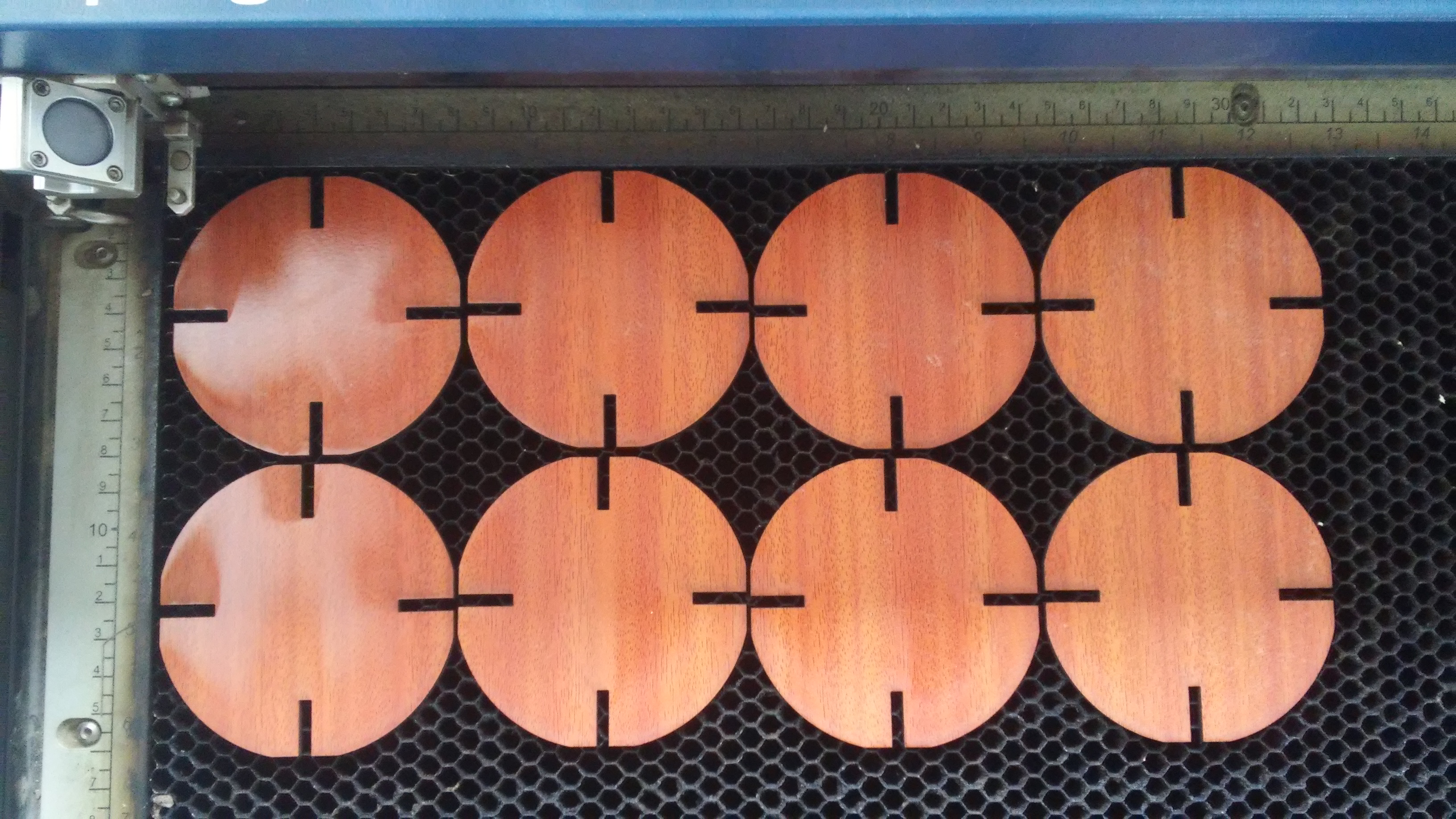
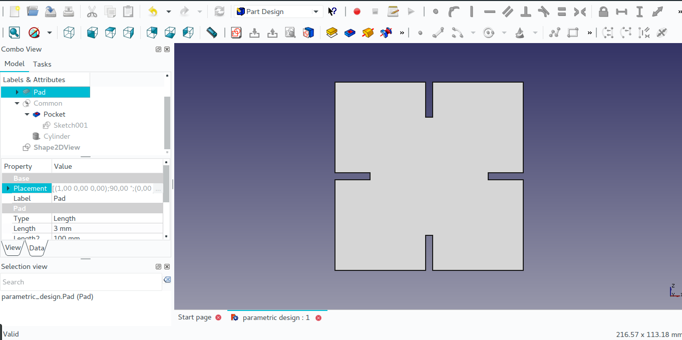
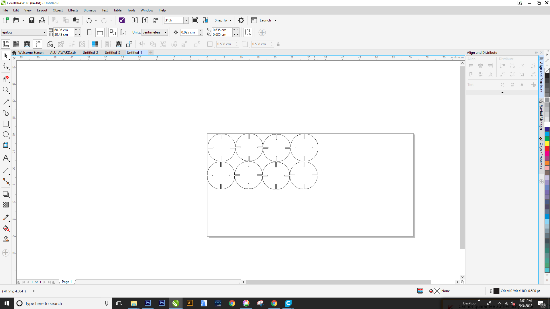
On the lasercutter I made a round-squared shape and made it parametric.
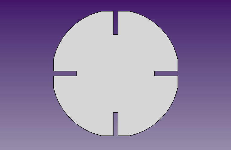
I started with a square shape and pocketed it where it will act like joint when combining with other part.
After inserted a cylinder for giving it a round like shape where after I made intersection between the square and the cylinder to get the final part.
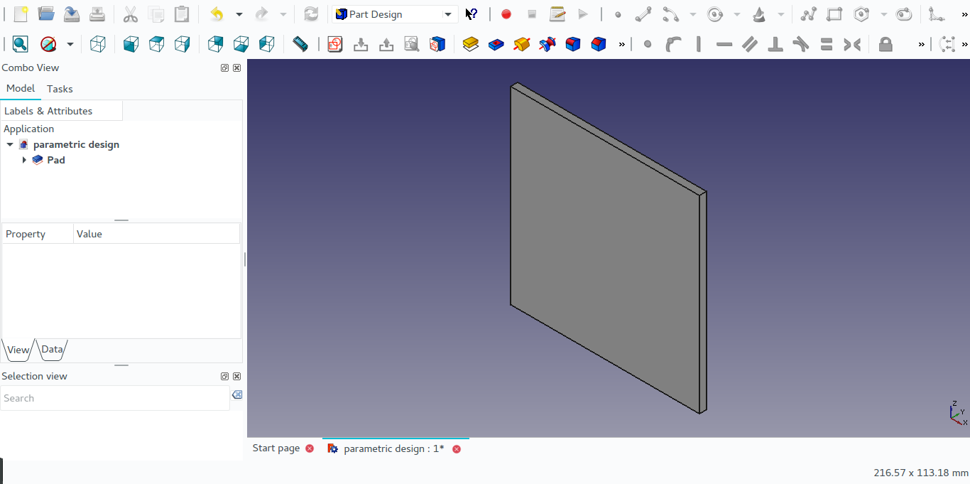
First I made a square shape of 80 mm of width.
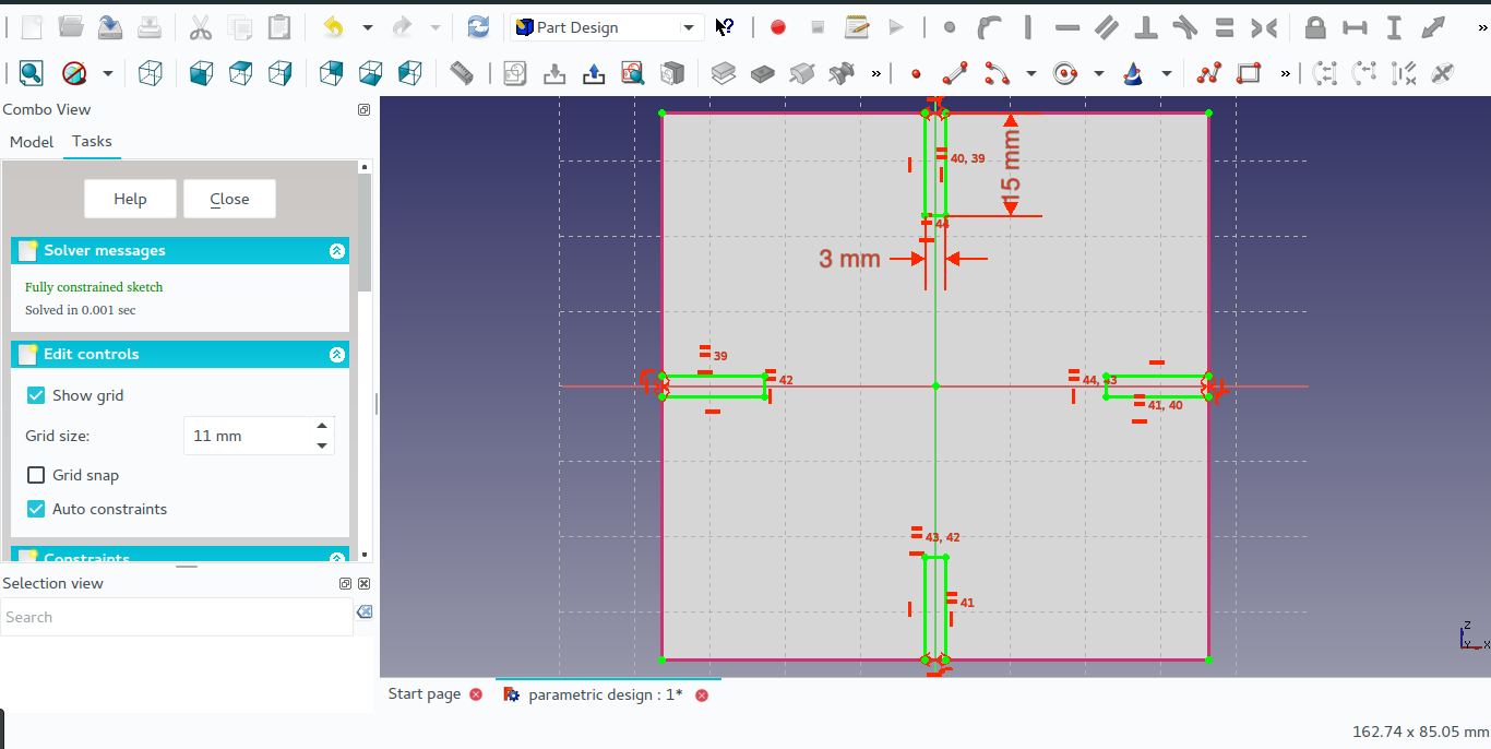
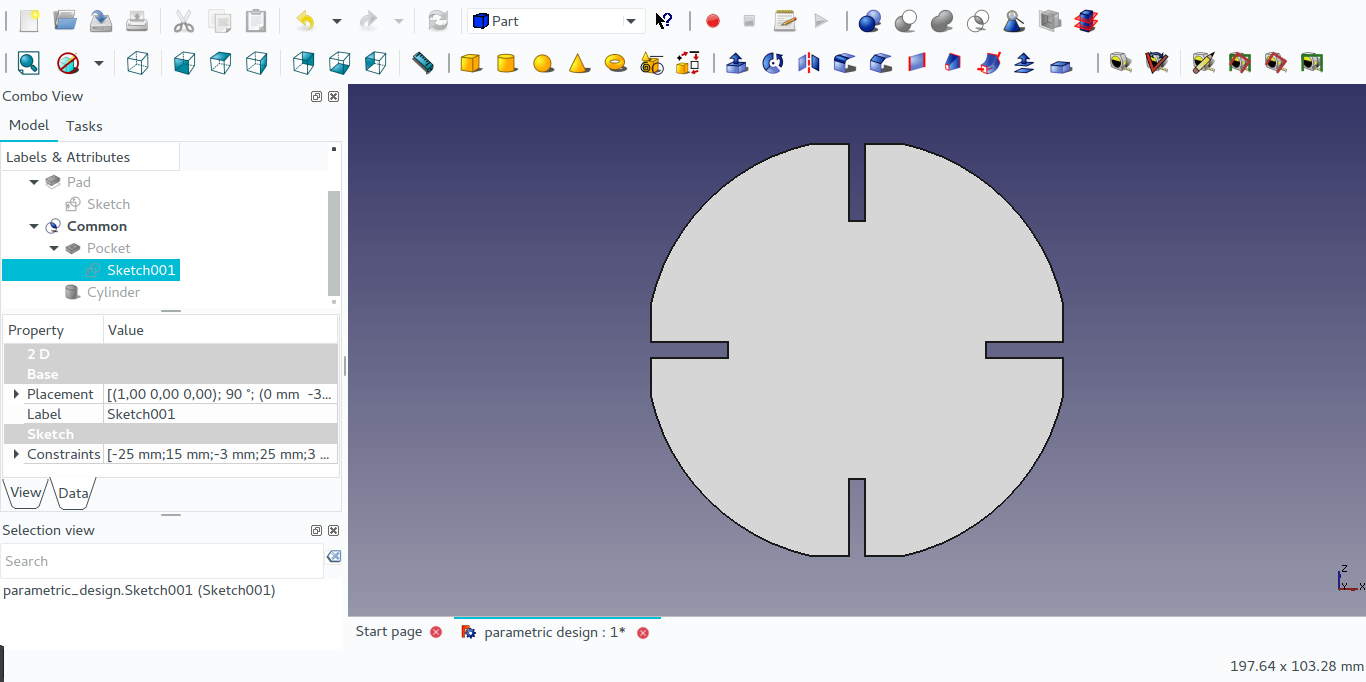
I sketched where I wanted to pocket.
I used parametric design in sketching which is method of linking dimensions and variables to a function in a such way that when the values of that function change, the part changes as well.
After pocketing the square shape, I inserted a cylinder inside the square shape and made an intersection of the two shape to give the final result.
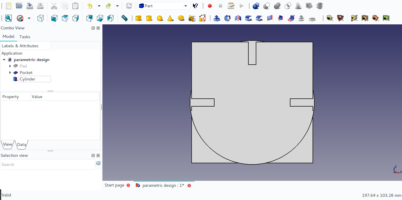
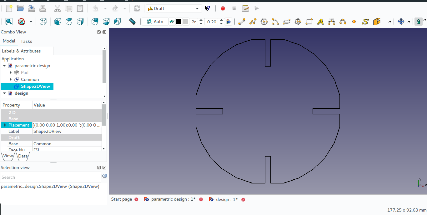
This is the final shape I made.
From there I converted the design I made into DXF file to be used in printing.
For printing my design I imported the design I made into corelDraw software, and I duplicated my design to print many parts.
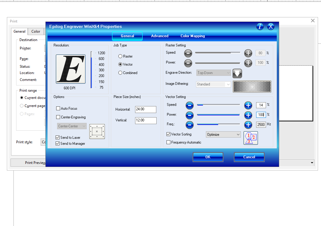
This is a screenshot of the epilog machine settings for printing on the wood.
The most important settings I choosed on the Epilog engraver properties was on:
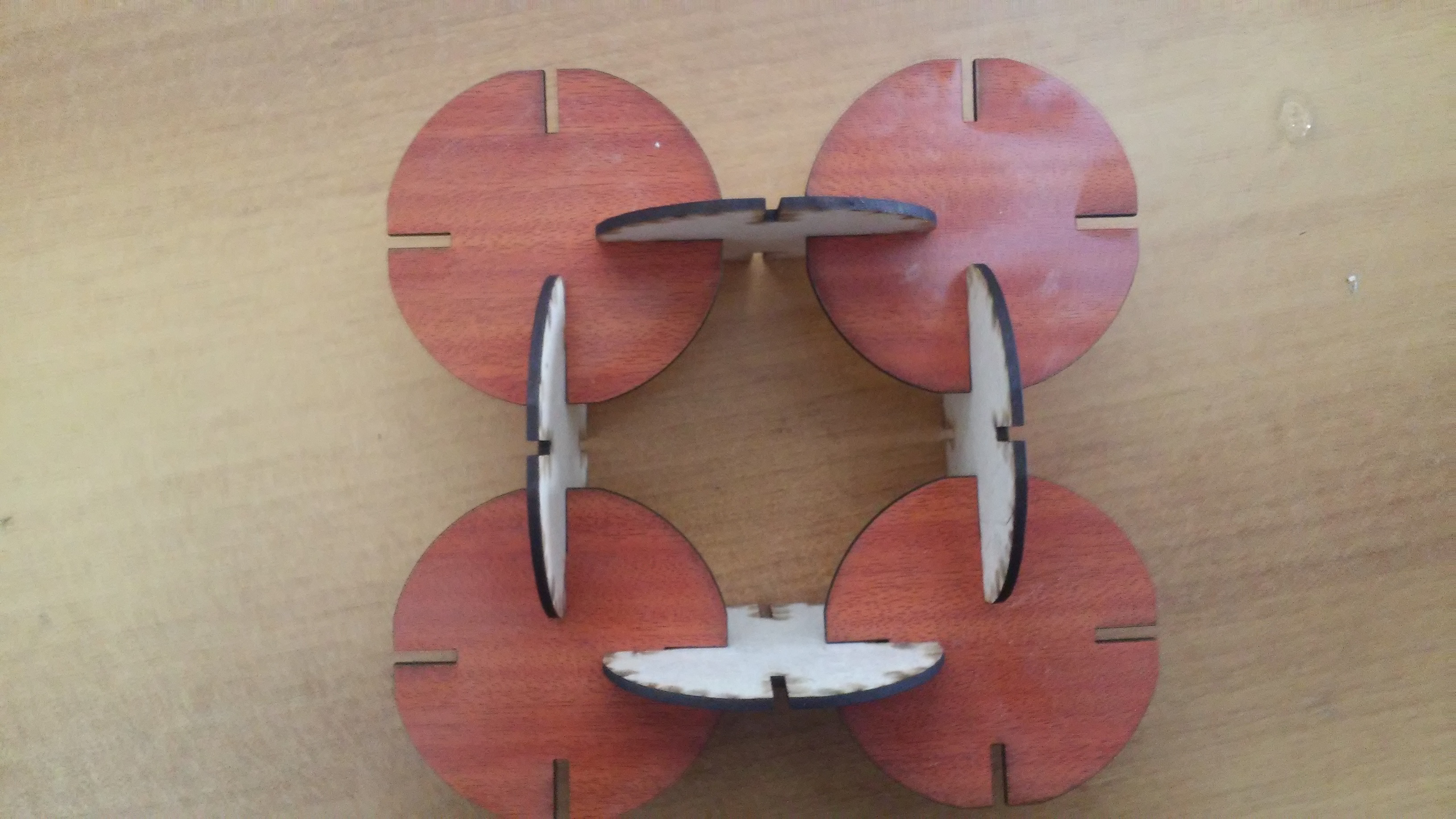
After cutting all parts I made in laser, assembled them to create something with them.