Computer-Controlled Machining
Work to be done
- Make something big on CNC machine.
Designing
For this assignement I choosed to design a standing desk that I could use when I am working, since I spend I alot of time sitting when I am working. I found this assignement as an opportunity to design that standing desk and also improve my skills in working with 3D designing software especially FreeCAD.
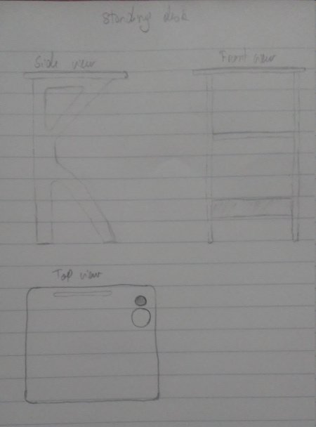
Before starting design I first skecthed out the design I wanted for the create in three different views.
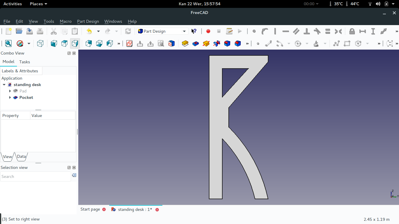
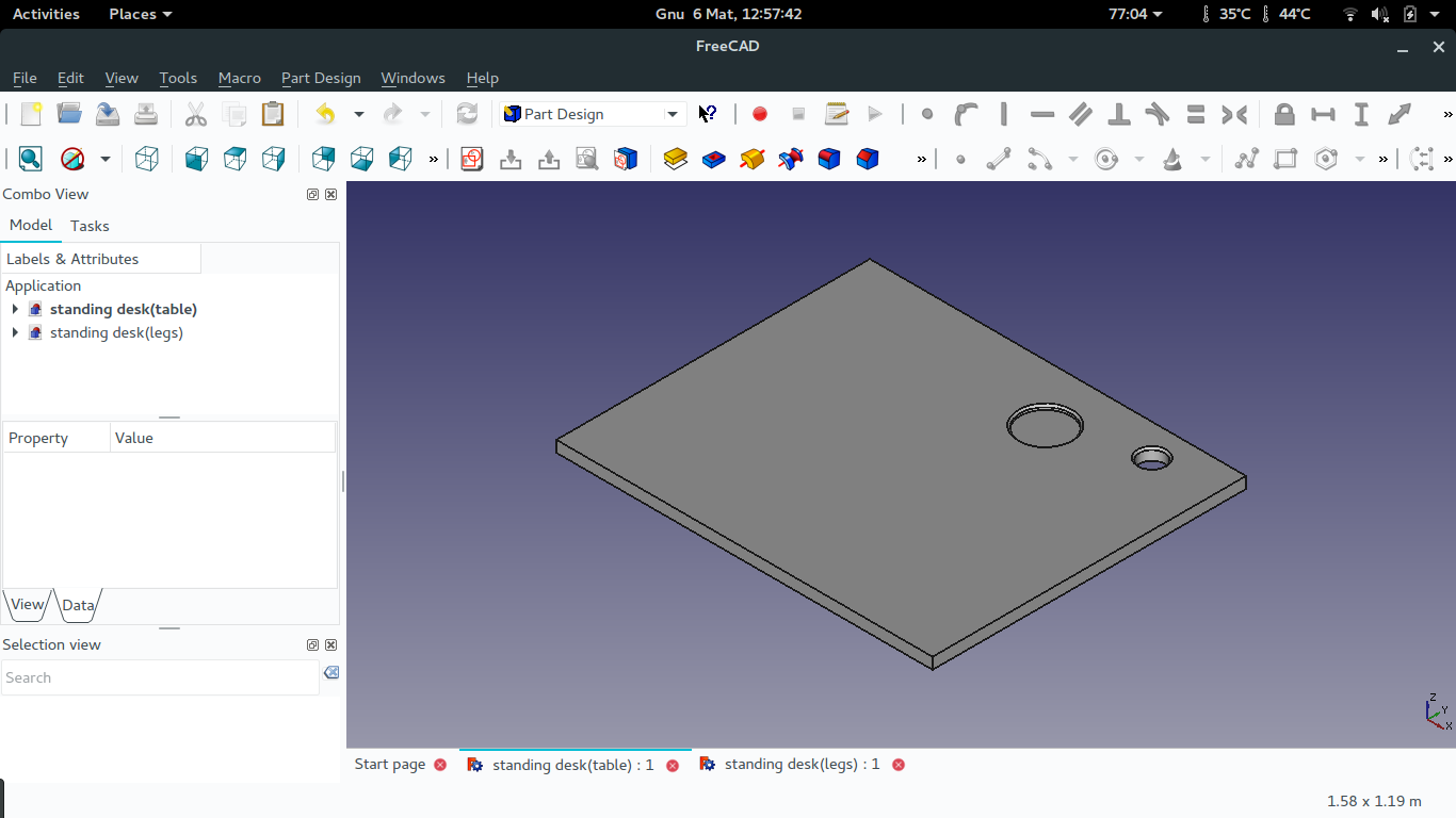
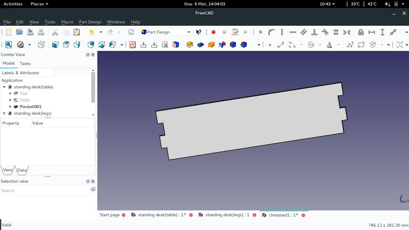
After sketching out my idea of the standing desk, I started designing from the side view(desk legs) which seemed to be the difficult part of the whole desk. It was not quit easy to make it since neither I nor my classmate had experience with FreeCAD. But I used the forum some of the problem I had though they were basic ones.
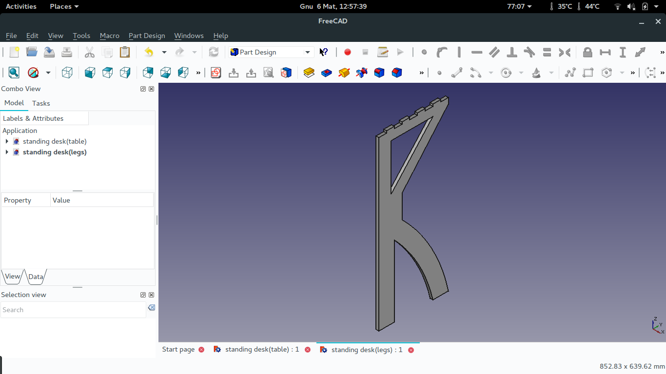

The top view of the standing desk was not complicated to design compared to the side view, but to cut it on the CNC machine was what I though will be difficult since it has 2 sides I want to be cutted, so will see when its time to cut it.
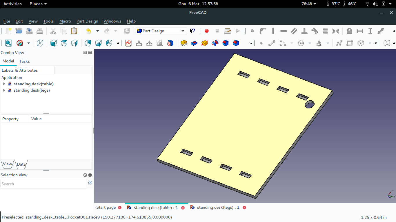
The front view of the standing desk is for holding the two legs of the desk in position which the desk more stable while working on it.
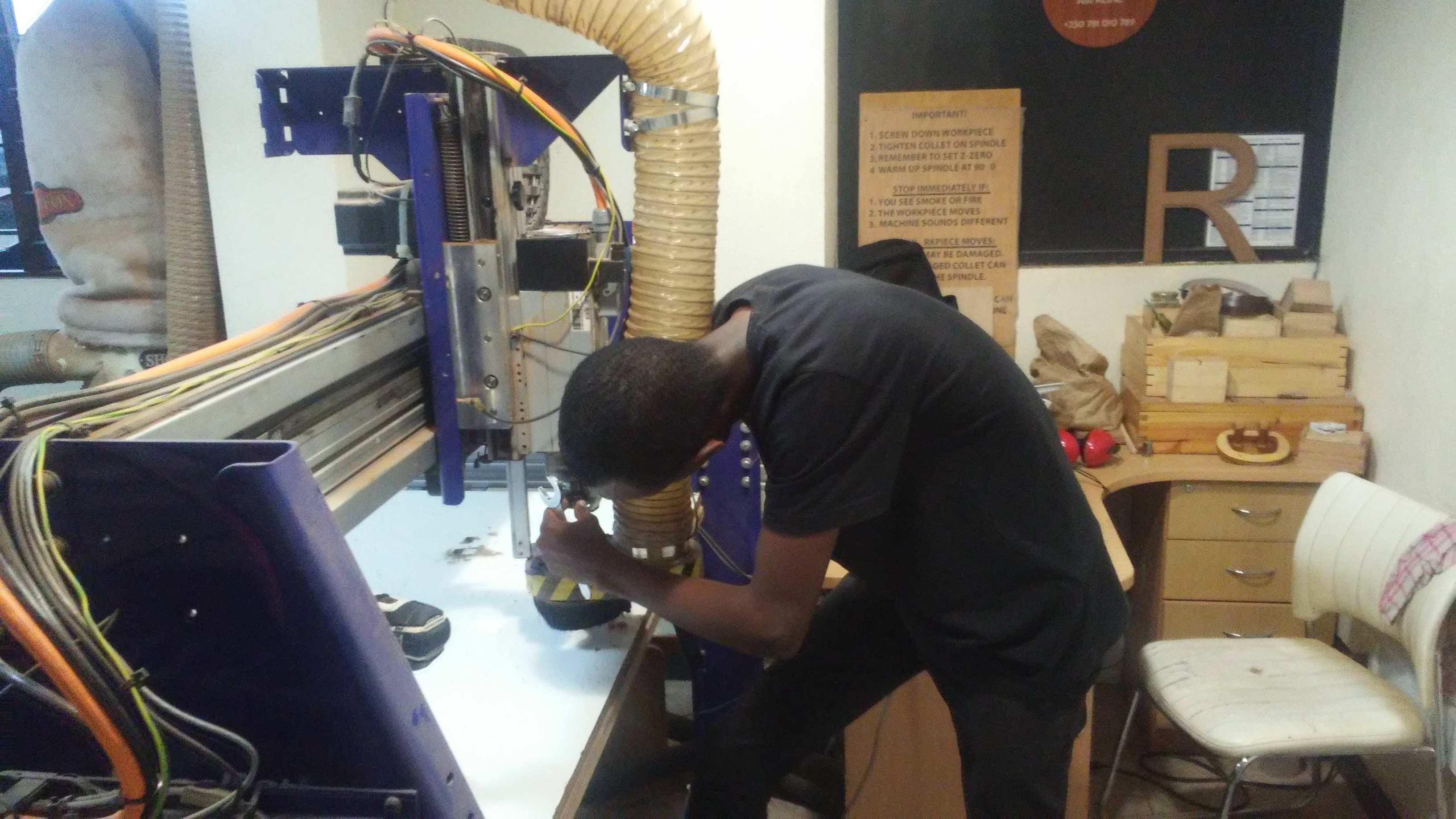
Setting up the machine
In setting the machine I started by fixing the board I was going to work on.
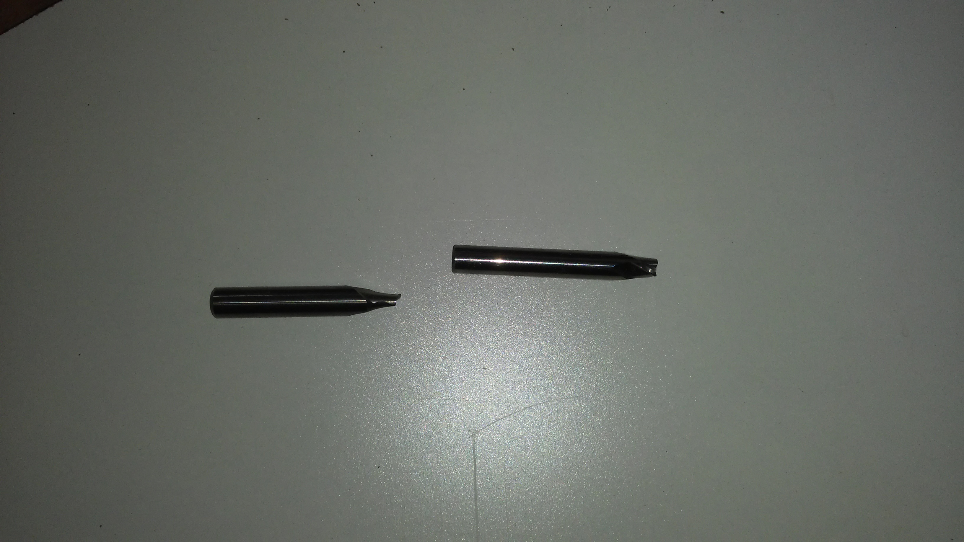
Then I set the cutting bit to use.
In cutting this design 2 bits where damaged during the process.
The first bit was broken when I send a command for starting milling before I started the spiddle to rotate and when It started the milling bit was broken.
The second bit was broken when I was trying to move the X and Y axis of the machine manualy while the Z axis was in a pocket it had created, I thought by moving the X and Y axis the machine would first try to move up the Z axis like it happens with the roland monoFab machine.
After fixing and setting the bit to use, I setted the write coordinates of X, Y and Z.
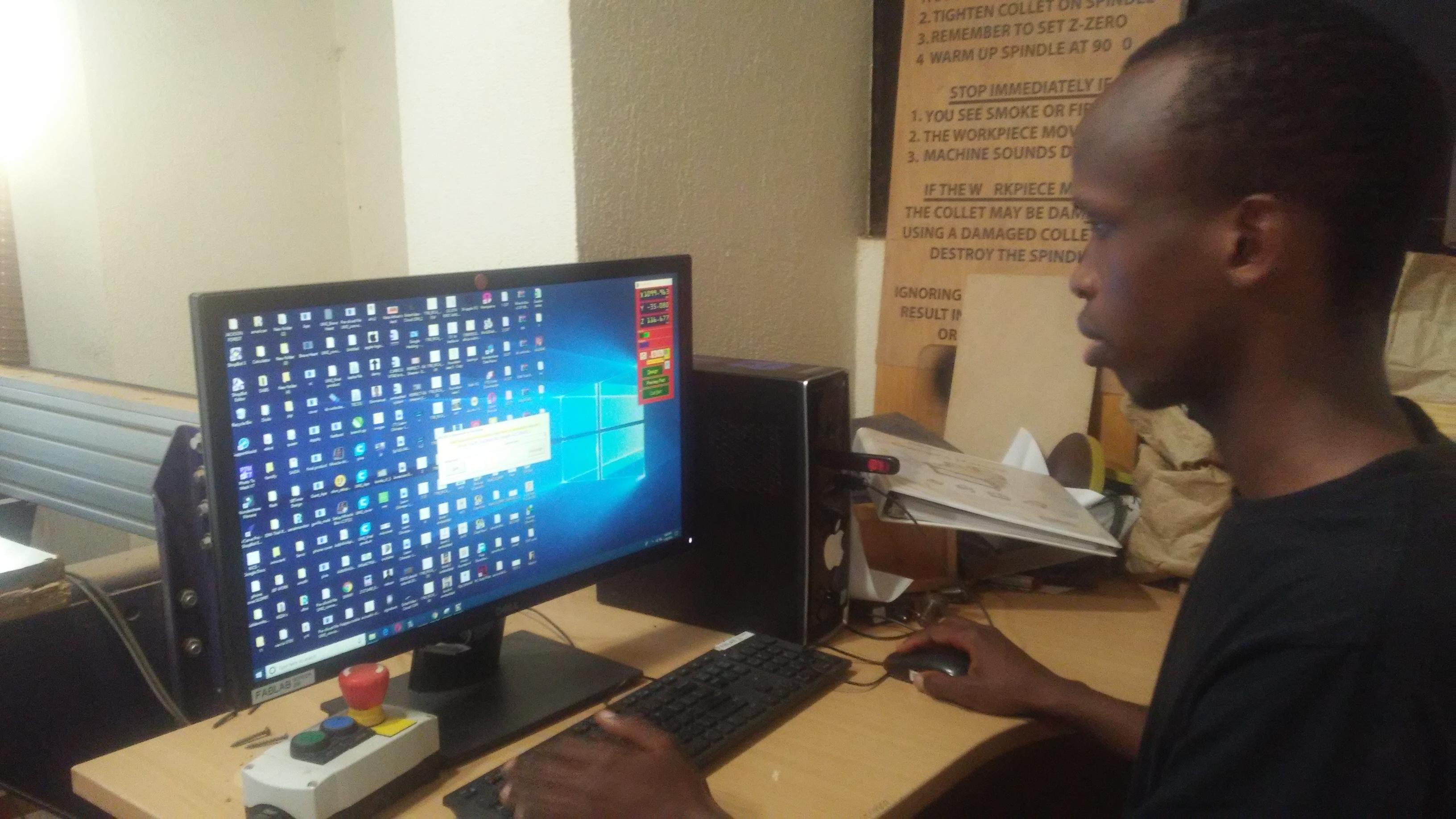
From there the next step was to setting the design I want to cut in the Vcarve software.
Software setting
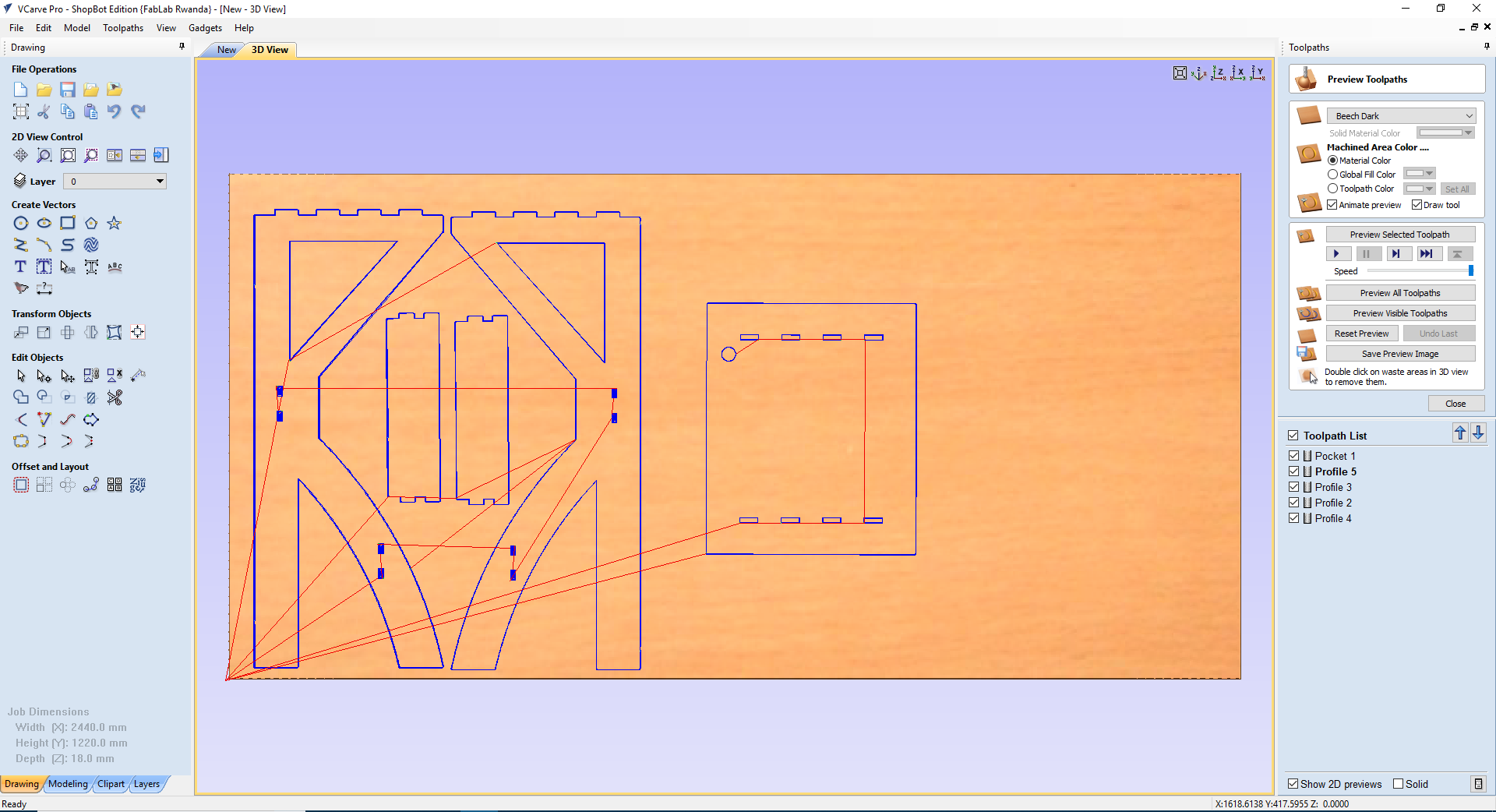
I first imported my files as vectors in the Vcarve software, then setted all as appropriate for those I have to pocket and the ones to profile, and added tabs for holding parts during cutting process.
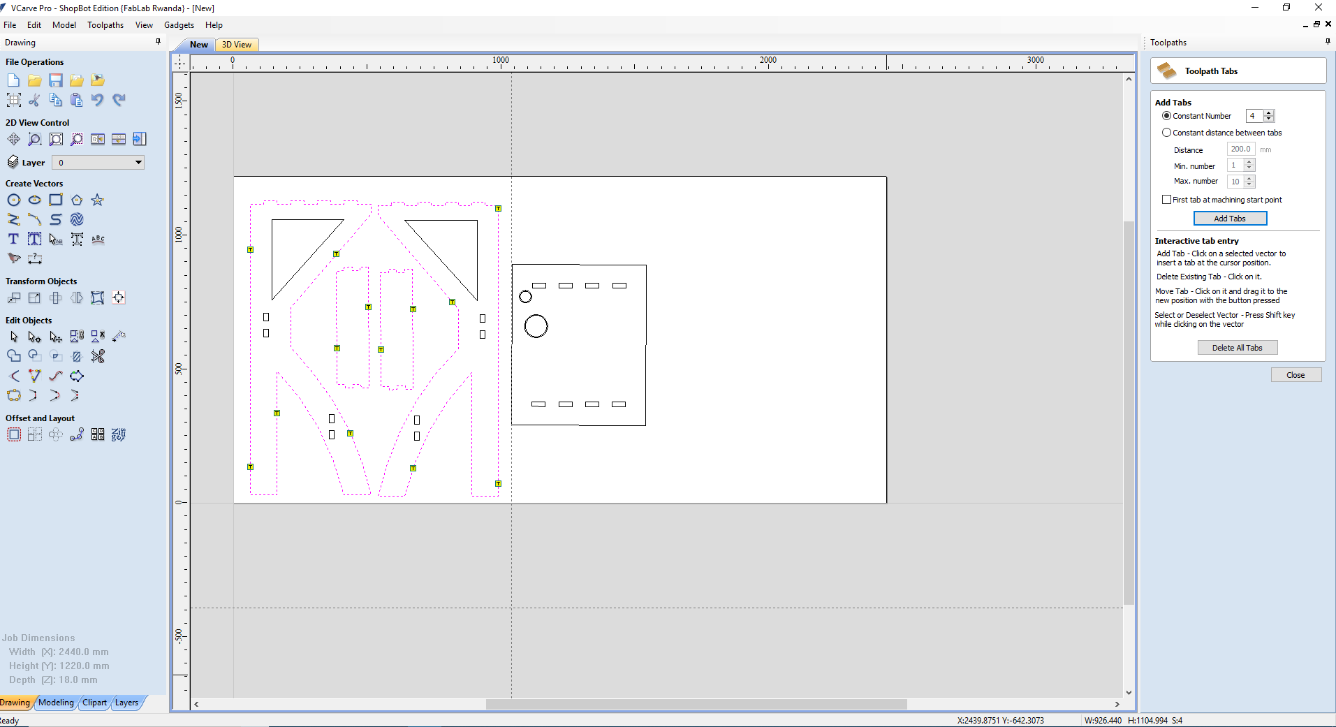
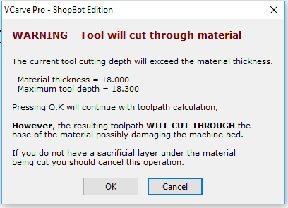
Here the software prompt to notifier the user that the tool will cut through the material.
This is the preview of all parts to be cutted.
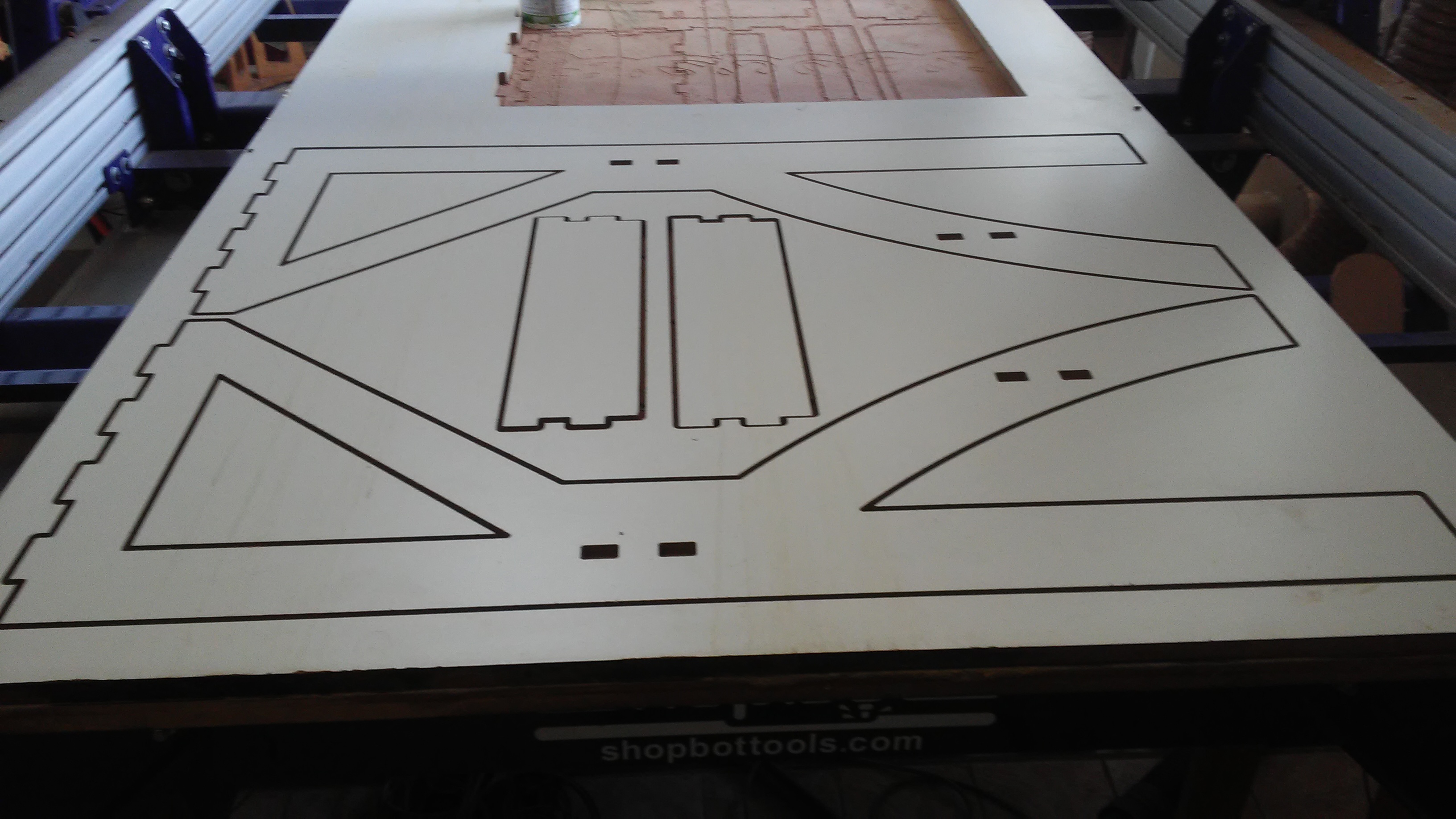
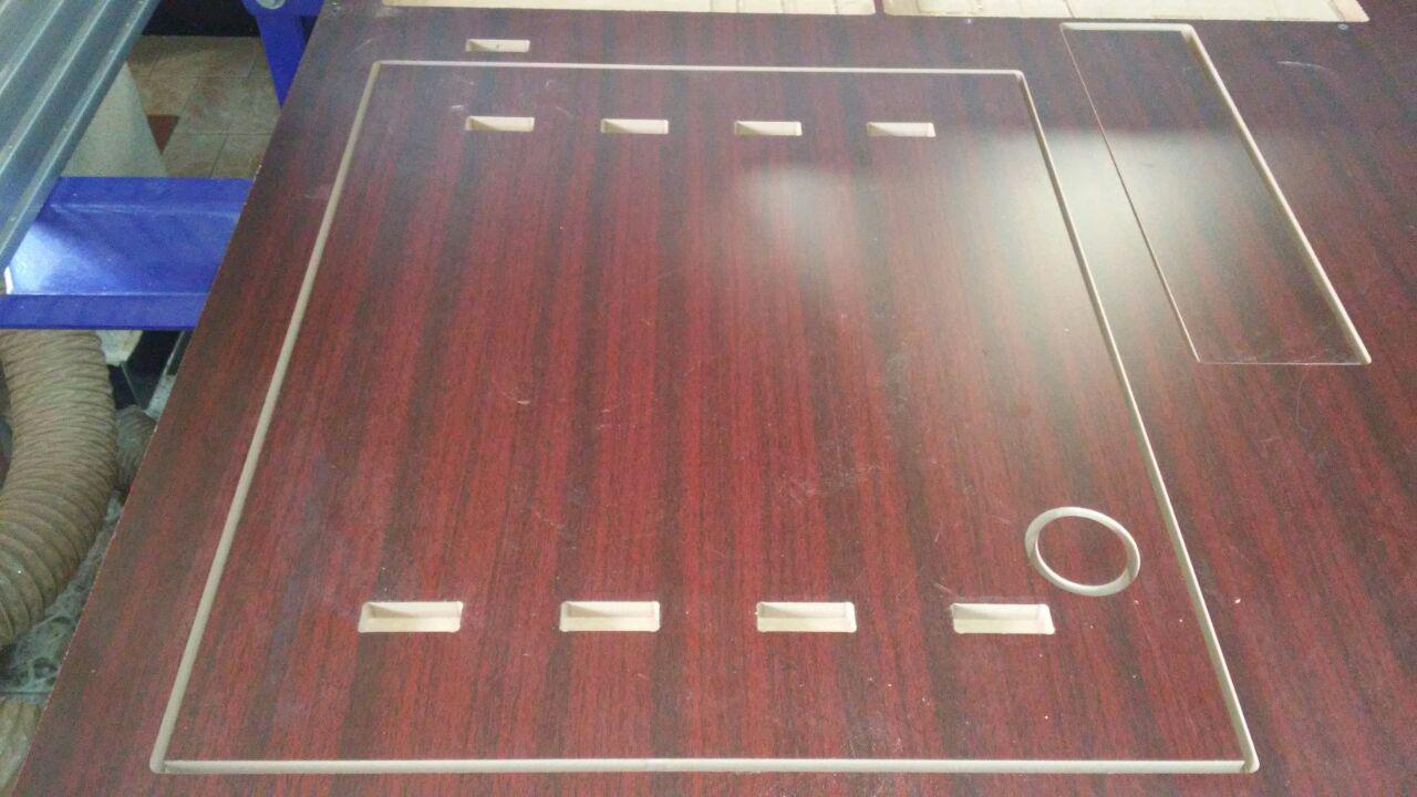
Because the material I was using the space left was small I removed the top view of the design and cutted the left parts.
after cutting this is the parts.
I also cutted the top view part of the design on a different material.
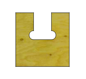
While I was editting this part my colleague ziad introduced me a feature called doggy bone used to easy the joint of two parts, because its difficult to make square inside corners using rounded end mill which leaves an extra material in the corners which obstructes the material passing through[image below].
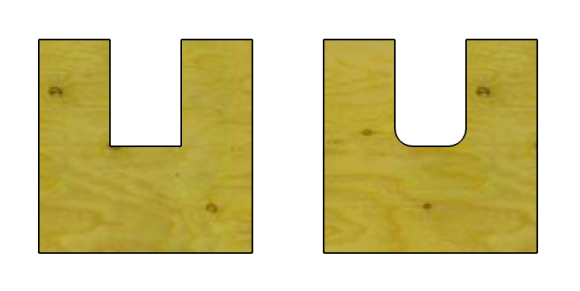
Doggy bone are used to add an extra space to faccilitate the material passing through. But I used it only on this part.
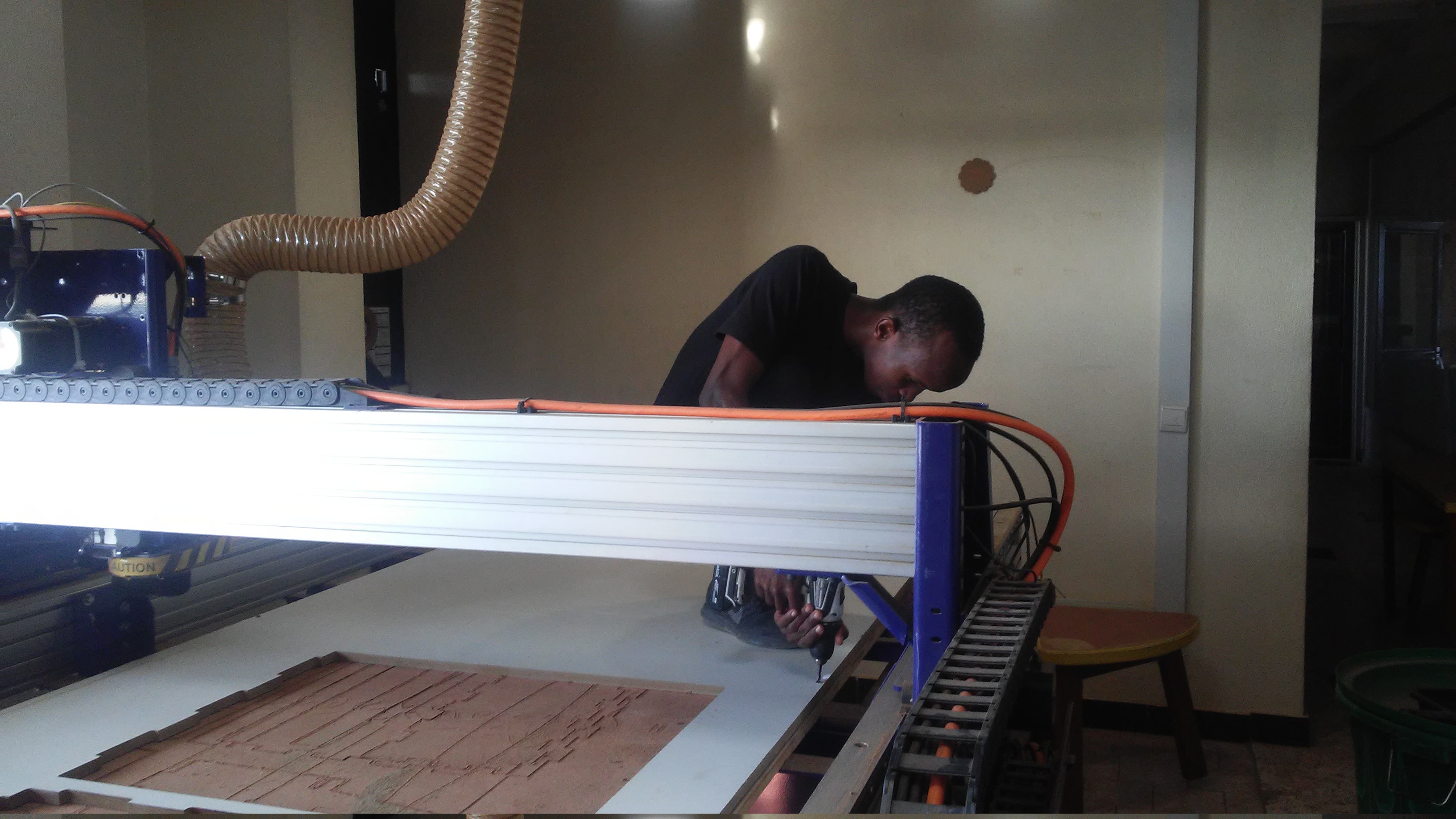
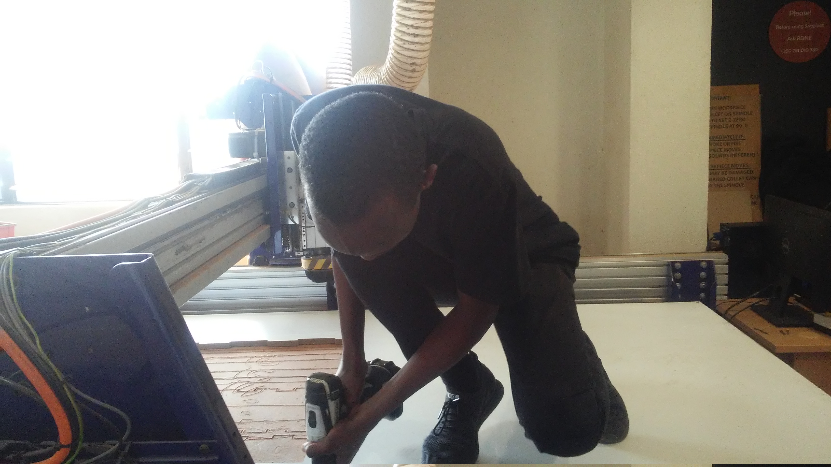
The last thing to be done was to assemble all parts and so that the standing desk could be used.
while assembling all the parts I had to use a sanding paper to make the parts fit together since one was bigger than the other.
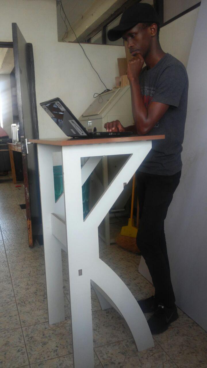
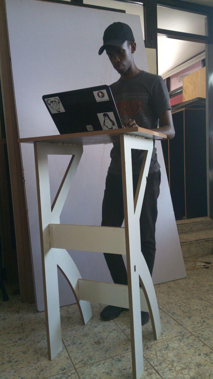
This is the Hero Shot of the standing desk being used.
Files used
![]()